EXFO IQ-5500 User manual

-~
ARTISAN
®
~I
TECHNOLOGY
GROUP
Your definitive source
for
quality
pre-owned
equipment.
Artisan Technology
Group
Full-service,
independent
repair
center
with
experienced
engineers
and
technicians
on staff.
We
buy
your
excess,
underutilized,
and
idle
equipment
along
with
credit
for
buybacks
and
trade-ins
.
Custom
engineering
so
your
equipment
works
exactly as
you
specify.
•
Critical
and
expedited
services
•
Leasing
/
Rentals/
Demos
• In
stock/
Ready-to-ship
•
!TAR-certified
secure
asset
solutions
Expert
team
ITrust
guarantee
I
100%
satisfaction
All
tr
ademarks,
br
a
nd
names, a
nd
br
a
nd
s a
pp
earing here
in
are
th
e property of
th
e
ir
r
es
pecti
ve
ow
ner
s.
Find the Exfo IQ-5523-ST-89 at our website: Click HERE

Instruction Manual
June 1999
P/N: MAN-116-I .4ACE
Fourth Edition
IQ-5500 — IQ-2123BP
PMD Multi-Analyzer

!"
#
$%&!%&"
'(!'")*+%,
'-
./000
12
#
2
3#4

CONTENTS
PMD Multi-Analyzer iii
CONTENTS
Certification Information ....................................................................................................vii
1I
NTRODUCTION ..........................................................................................................................1-1
1.1 IQ-200 Optical Test System Product Line ......................................................................1-1
1.2 Unpacking and Inspection ..............................................................................................1-2
1.3 Safety Conventions .........................................................................................................1-2
1.4 Transportation and Storage ............................................................................................1-3
1.5 Getting Help ....................................................................................................................1-3
2H
ARDWARE INFORMATION ..........................................................................................................2-1
2.1 IQ-5500 Front Panel Description ....................................................................................2-1
2.2 IQ-2123BP Front Panel Description ...............................................................................2-2
2.3 LED Push Button ............................................................................................................2-3
2.4 Module Insertion .............................................................................................................2-3
2.5 Optical Connections ........................................................................................................2-4
2.6 Module Removal .............................................................................................................2-7
3O
VERVIEW .................................................................................................................................3-1
4S
OFTWARE DESCRIPTION ...........................................................................................................4-1
4.1 Loading the Application Software ...................................................................................4-1
4.2 IQ-5500 PMD Multi-Analyzer Software Description ........................................................4-2
4.3 IQ-2123BP Light Source Software Description ...............................................................4-8
4.4 Status Bar .....................................................................................................................4-12
4.5 Monitor Window ............................................................................................................4-13
4.6 Exiting the Application Software ...................................................................................4-15
5O
PERATION ...............................................................................................................................5-1
5.1 Source Activation/Deactivation .......................................................................................5-1
5.2 Source Setup ..................................................................................................................5-1
5.3 Preparing for Measurements ..........................................................................................5-3
5.4 Entering User Information ...............................................................................................5-5
5.5 Entering DUT Information ...............................................................................................5-6
5.6 Setting Acquisition Parameters .......................................................................................5-8
5.7 Acquiring a Trace ..........................................................................................................5-12
5.8 Viewing Acquisition Results ..........................................................................................5-13
5.9 Selecting Views with the Zoom .....................................................................................5-14
5.10 Selecting a Trace to View .............................................................................................5-15
5.11 Viewing Statistics ..........................................................................................................5-18

CONTENTS
iv IQ-5500 — IQ-2123BP
5.12 Viewing Acquisition Information ...................................................................................5-19
5.13 Customizing Acquisitions .............................................................................................5-23
6M
ANAGING DATA ......................................................................................................................6-1
6.1 Generating a Results Table from the File Menu ............................................................6-1
6.2 Saving and Retrieving Files ...........................................................................................6-1
6.3 Opening and Saving Configuration Files ........................................................................6-2
6.4 Opening and Saving Templates .....................................................................................6-3
6.5 Printing Data ..................................................................................................................6-4
7T
HE GPIB INTERFACE ...............................................................................................................7-1
7.1 Command Structure .......................................................................................................7-1
7.2 Common Commands .....................................................................................................7-2
7.3 System Commands ........................................................................................................ 7-8
7.4 Quick Reference Command Trees ...............................................................................7-29
7.5 GPIB Error Messages ..................................................................................................7-33
8T
ECHNICAL SPECIFICATIONS ......................................................................................................8-1
8.1 IQ-5500 PMD Analyzer ..................................................................................................8-1
8.2 IQ-2123BP Light Source ................................................................................................8-2
9M
AINTENANCE AND TROUBLESHOOTING ....................................................................................9-1
9.1 Module Maintenance ......................................................................................................9-1
9.2 Cleaning Fiber Ends .......................................................................................................9-1
9.3 Cleaning Optical Ports ...................................................................................................9-1
9.4 Troubleshooting .............................................................................................................9-2
10 WARRANTY .............................................................................................................................10-1
10.1 General Information .....................................................................................................10-1
10.2 Liability .........................................................................................................................10-2
10.3 Exclusions ....................................................................................................................10-2
10.4 Certification ..................................................................................................................10-2
10.5 Service and Repairs .....................................................................................................10-2
APPENDIX A – PMD THEORY ..........................................................................................................A-1
GLOSSARY ...................................................................................................................... GLOSSARY-1
INDEX ......................................................................................................................................INDEX-1

FIGURES
PMD Multi-Analyzer v
FIGURES
Figure 2-1. Module Nameplate ...........................................................................................2-1
Figure 2-2. Front Panel of the IQ-5500 PMD Analyzer Module ..........................................2-1
Figure 2-3. Front Panel of the IQ-2123BP Light Source Module ........................................2-2
Figure 2-4. EUI Base Plate Options ...................................................................................2-5
Figure 2-5. EUI Connector Adaptor ....................................................................................2-5
Figure 2-6. Mounting EUI Connector Adaptor ....................................................................2-6
Figure 2-7. Removing an IQ Module ..................................................................................2-7
Figure 4-1. IQ-5500 PMD Main Window .............................................................................4-2
Figure 4-2. PMD Graph Axes Description ..........................................................................4-6
Figure 4-3. IQ-2123BP Light Source Main Window ............................................................4-8
Figure 4-4. IQ-5500 Monitor Window ................................................................................4-13
Figure 4-5. IQ-2123BP Monitor Window ...........................................................................4-14
Figure 5-1. Light Source Activation/Deactivation Buttons and Status Box .........................5-1
Figure 5-2. Increase/Decrease Buttons and Attenuation Edit Box .....................................5-2
Figure 5-3. Modulation List Box ..........................................................................................5-2
Figure 5-4. Wavelength Button and Box .............................................................................5-3
Figure 5-5. PMD Measurement Setup with an IQ-2123BP Light Source Module ...............5-4
Figure 5-6. User Information Window .................................................................................5-5
Figure 5-7. DUT Page ........................................................................................................5-6
Figure 5-8. Weak Mode Coupling Fiber Measured with Strong Coupling Settings .............5-7
Figure 5-9. Measurement Page ..........................................................................................5-8
Figure 5-10. Multiple Measurement Dialog .........................................................................5-10
Figure 5-11. Manual Scan Dialog .......................................................................................5-11
Figure 5-12. Timed Scan Dialog .........................................................................................5-11
Figure 5-13. PMD Results Graph .......................................................................................5-13
Figure 5-14. Results Page ..................................................................................................5-13
Figure 5-15. Zoom Page .....................................................................................................5-14
Figure 5-16. Selection Page ...............................................................................................5-15
Figure 5-17. Statistics Page ...............................................................................................5-18
Figure 5-18. Measurement Information Window .................................................................5-20
Figure 5-19. Measurement Information Window .................................................................5-22
Figure 5-20. Option Page ...................................................................................................5-23
Figure 5-21. Browse Path Dialog ........................................................................................5-24
Figure 5-22. File Name Page .............................................................................................5-25
Figure 5-23. Module Page ..................................................................................................5-26
Figure 5-24. Graphic Page .................................................................................................5-28
Figure 5-25. Table Page .....................................................................................................5-31
Figure 7-1. GPIB Error Message Format ..........................................................................7-33
Figure A-1. PMD Delay in Perfect and Birefringent Fiber .................................................. A-2

TABLES
vi IQ-5500 — IQ-2123BP
TABLES
Table 4-1. IQ-5500 Main Window Drop-Down Menus ......................................................4-3
Table 4-2. IQ-5500 Function Buttons Description .............................................................4-5
Table 4-3. Status Bar Information Description .................................................................. 4-7
Table 4-4. IQ-2123BP Main Window Drop-Down Menus .................................................4-9
Table 4-5. IQ-2123BP Function Buttons .........................................................................4-10
Table 4-6. Data Display Boxes .......................................................................................4-11
Table 4-7. Module Control Status ...................................................................................4-12
Table 5-1. Available Scanning Ranges According to Device Type ...................................5-9
Table 5-2. Zoom Functions .............................................................................................5-14
Table 5-3. Information Availability Indicators ..................................................................5-16
Table 5-4. Information Available in the Selection Page ..................................................5-16
Table 5-5. Information Available in the Statistics Page ...................................................5-18
Table 5-6. Threshold Correspondance ...........................................................................5-27
Table 5-7. Table Report Column Headings ....................................................................5-32
Table 7-1 Command Commands Summary ....................................................................7-2
Table 7-2. IQ-5500 PMD Analyzer Command Tree ........................................................7-29
Table 7-3. IQ-2100 Light Source Command Tree ...........................................................7-33
Table 7-4. IQ-5500 PMD Analyzer Error Messages .......................................................7-34
Table 7-5. IQ-2100 Light Source Error Messages ..........................................................7-36
Table 9-1. Problems, Causes, and Recommended Actions .............................................9-2

CERTIFICATION INFORMATION
PMD Multi-Analyzer vii
CERTIFICATION INFORMATION
' 566))783(
% 7/6%%9'
'
:
2
:
;
' 5</<,=7*>
% 7/6%%9'
'
:
2
:
;
WARNING
';
;:
:
?'*
8%'-

CERTIFICATION INFORMATION
viii IQ-5500 — IQ-2123BP
' 566))783(
% 73%
' 5</<,=7*>
% 73%

INTRODUCTION
PMD Multi-Analyzer 1-1
!""#$%&
1I
NTRODUCTION
!"
566))7(83( 5</<,=7*>
5<))'>
@
A
B
B
B ;
B
'7838('
:
1.1 IQ-200 Optical Test System Product Line
' 5<))'>
'21C 5
> 5<))'>
;'
5<),8 5<)D
;?;
5<)D;? 5<)D7%;%
5<))'> 5>
!""#$'

INTRODUCTION
1-2 IQ-5500 — IQ-2123BP
()*
1.2 Unpacking and Inspection
' 566))A
B 5</<,=7*>
B
B %5
B 3%
B 2!"
':
E2
:
1.3 Safety Conventions
'A
WARNING 9( :
-3
WARNING
:
CAUTION 9( :
3
CAUTION:
IMPORTANT 9
2

INTRODUCTION
PMD Multi-Analyzer 1-3
$*
1.4 Transportation and Storage
8
''
(A
B 722
B >
B E
B 2
1.5 Getting Help
'%>&
FA,) +A)) 8
GD6&
H5%&/8,&F
%
/+))DD,,0,D!?>%"
'A!G/+"D+,)<//
;A!G/+"D+,</F)
I;
;
%$*8(
/))%
F+,6,JJ
'A,,/,GD,))<)
;A,,/,GD60)0,

'2

HARDWARE INFORMATION
PMD Multi-Analyzer 2-1
++""%
2H
ARDWARE INFORMATION
'
Figure 2-1. Module Nameplate
$*
*
2.1 IQ-5500 Front Panel Description
Figure 2-2. Front Panel of the IQ-5500 PMD Analyzer Module
Ver.
Mfg.
date
P/N
S/N
Made in Canada QST-94
465 Godin Ave.
Vanier, Que., Canada G1M 3G7
This device complies with part 15 of the FCC rules. Operation is
subject to the following two conditions: (1) this device may not cause
harmful interference and (2) this device must accept any interference
received, including interference that may cause undesired operation.
Part number
(identifying configuration
and connector type) Product version
Manufacture date
Serial number
Fiber type IQ-55xx-xxx
Fiber 9/125 µm
25634-IQ
A-1.0
July 97
PMD ANLYZER
IQ-5500
Connector port
LED push button
HARDWARE INFORMATION
2-2 IQ-5500 — IQ-2123BP
!,!-.%%
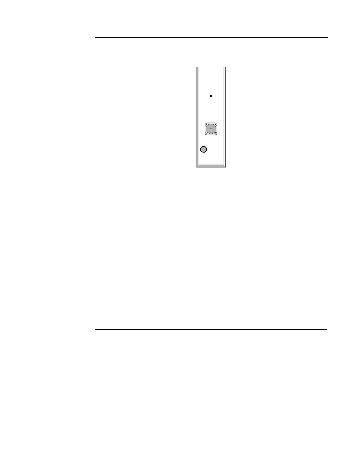
2.2 IQ-2123BP Front Panel Description
Figure 2-3. Front Panel of the IQ-2123BP Light Source Module
2.2.1 Active LED
1*3
2.2.2 Source Port
IMPORTANT
!"#$
%$%%
Source port
LED push button
Active LED
LIGHT SOURCE
IQ-2100
ACTIVE

HARDWARE INFORMATION
PMD Multi-Analyzer 2-3
&%.
2.3 LED Push Button
'*3A
B 1*3
B 7*3
B 7*3
$*
'/* 0 ,-
2.4 Module Insertion
CAUTION
%!&'()*
!&'(+,#
!&'()-!&'(+
'
/ ' 5<),K 5<)D
< 5' 5<),K 5<)D
(
IMPORTANT
.%"!&'()-!&'(+
"#
%%
!&'()-!&'(+

HARDWARE INFORMATION
2-4 IQ-5500 — IQ-2123BP
#
2.5 Optical Connections
'
2.5.1 Fiber Connections
'
/ &
< 3
'
/ 9
< >!"
,
G
6 %3
HARDWARE INFORMATION
PMD Multi-Analyzer 2-5
#
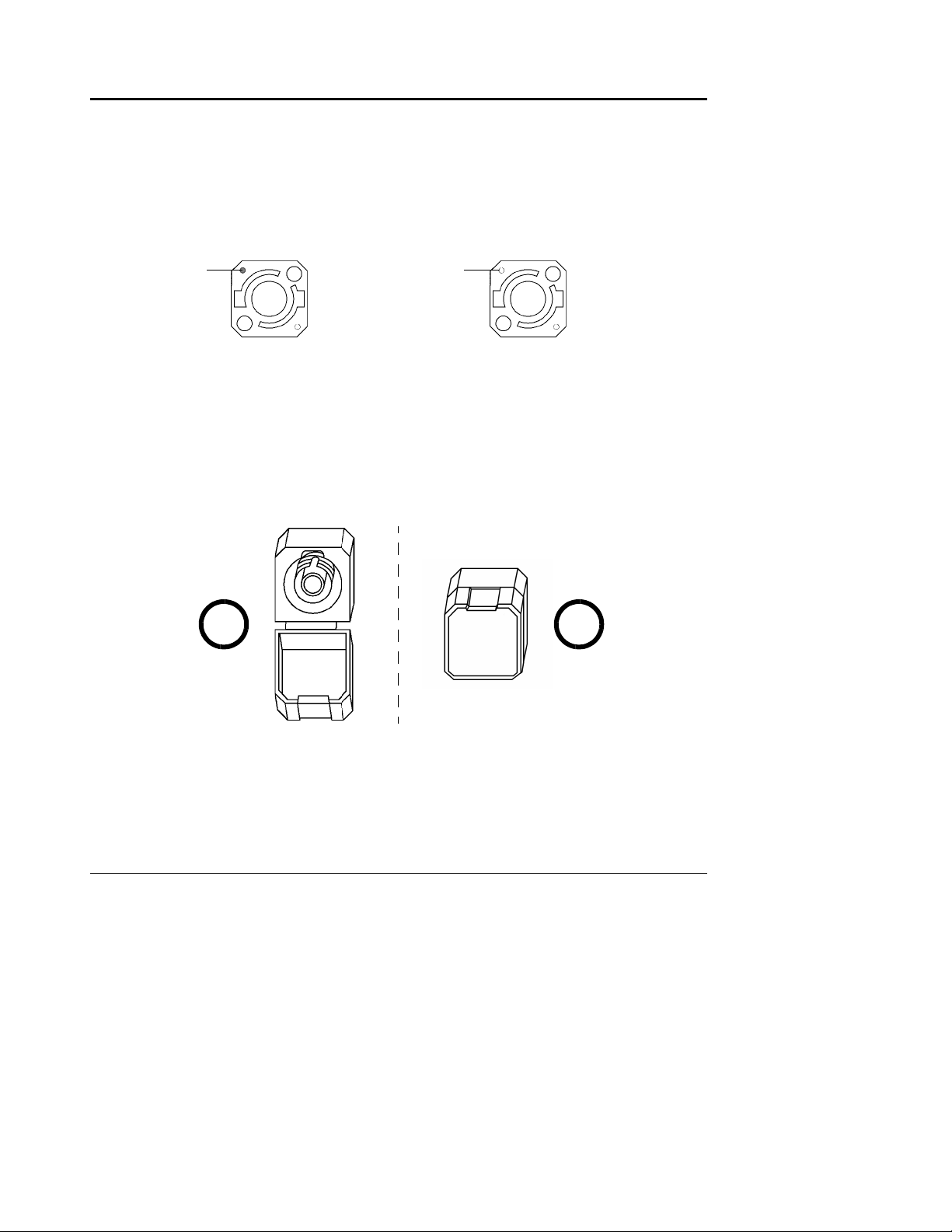
2.5.2 EXFO Universal Interface (EUI)
'? ;!7%"
!?7%"
7% <G
Figure 2-4. EUI Base Plate Options
'? ?
/ #?
<6
< %
Figure 2-5. EUI Connector Adaptor
Green dot
indicates
APC
option
Bare metal
UPC
indicates
option
1 2

HARDWARE INFORMATION
2-6 IQ-5500 — IQ-2123BP
#
,
G '22
Figure 2-6. Mounting EUI Connector Adaptor
3 4

HARDWARE INFORMATION
PMD Multi-Analyzer 2-7
'1
2.6 Module Removal
CAUTION
%!&'()*
!&'(+,%#%
!&'()-!&'(+
' 5<),K 5<)D
/ 82 5<),K 5<)D
< 22
<F
,
Figure 2-7. Removing an IQ Module
G 7
3
2
Locking
mechanism
This manual suits for next models
1
Table of contents
Other EXFO Measuring Instrument manuals


EXFO
EXFO FTB-5800 User manual

EXFO
EXFO FTB-5600 User manual

EXFO
EXFO FTB-1v2 Pro User manual

EXFO
EXFO Optical Power Expert User manual

EXFO
EXFO FTB-5230S User manual

EXFO
EXFO T100S-HP Series Operating instructions

EXFO
EXFO T100S-HP Series User manual

EXFO
EXFO IQS-5320 User manual

EXFO
EXFO IQS-5320-EI User manual

EXFO
EXFO FOT-5200 User manual


Popular Measuring Instrument manuals by other brands


Honeywell
Honeywell Themis alpha EI2 Operating instructions for consumers

Magnescale
Magnescale DK812 Series instruction manual

LaserLiner
LaserLiner 4K5 RA 800 manual

MR
MR MSENSE DGA 2 operating instructions

Hanna Instruments
Hanna Instruments HI 96821 instruction manual

PCE Instruments
PCE Instruments PCE-CT 21BT user manual


![Mr Beam dreamcut [s] manual](/data/manuals/os/t/osto/sources/mr-beam-dreamcut-s-manual.jpg "Mr Beam dreamcut [s] manual")
