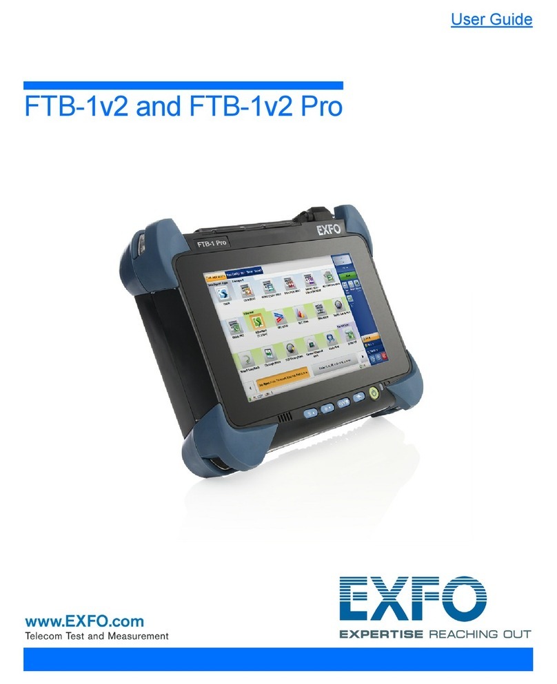
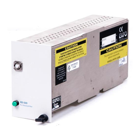
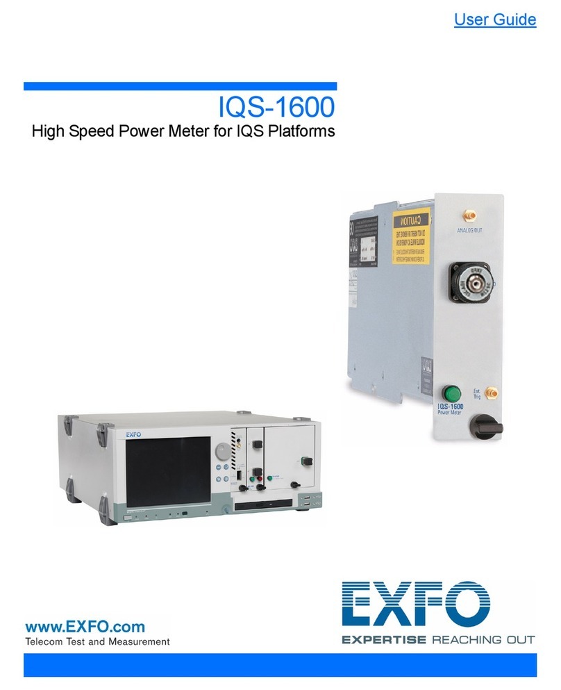
EXFO IQS-5320 User manual

Multi-Wavelength Meter
IQS-5320
User Guide
P/N: 1035496
June 2002
If the equipment described herein
bears the symbol, the said
equipment complies with the
applicable European Union
Directive and Standards mentioned
in the Declaration of Conformity.

All rights reserved. No part of this publication may be reproduced, stored in
a retrieval system, or transmitted in any form, be it electronically,
mechanically, or by any other means such as photocopying, recording, or
otherwise, without the prior written permission of EXFO Electro-Optical
Engineering Inc. (EXFO).
Information provided by EXFO is believed to be accurate and reliable.
However, no responsibility is assumed by EXFO for its use nor for any
infringements of patents or other rights of third parties that may result from
its use. No license is granted by implication or otherwise under any patent
rights of EXFO.
EXFO’s Commerce And Government Entities (CAGE) code under the North
Atlantic Treaty Organization (NATO) is 0L8C3.
The information contained in this publication is subject to change without
notice.
© 2002 EXFO Electro-Optical Engineering Inc.
Words that EXFO considers trademarks have been identified as such.
However, neither the presence nor absence of such identification affects
the legal status of any trademark.
Units of measurement in this document conform to SI standards and
practices.

Contents
Multi-Wavelength Meter iii
Contents
Certification Information ....................................................................................................... vi
1 Introducing the IQS-5320 Multi-Wavelength Meter ................................... 1
Main Features .........................................................................................................................1
Typical Applications ................................................................................................................2
MWM Measurement Principle .................................................................................................3
2 Safety Information ....................................................................................... 5
Safety Conventions .................................................................................................................5
Laser Safety Information .........................................................................................................5
3 Getting Started with Your Multi-Wavelength Meter .................................. 7
Inserting and Removing Test Modules ....................................................................................7
Launching the IQS-5320 Multi-Wavelength Meter Application .............................................11
Adjusting Window Height ....................................................................................................14
Exiting the Application .........................................................................................................14
4 Setting Up Your Multi-Wavelength Meter ................................................. 15
Setting Power Units ..............................................................................................................16
Setting Wavelength Units .....................................................................................................17
Displaying Interchannel Data ................................................................................................18
Setting the Detection Threshold ...........................................................................................18
Selecting a Referenced Power ...............................................................................................20
Selecting a Transmission Medium .........................................................................................21
Setting a Power Offset ..........................................................................................................22
Creating Channels and Channel Lists ....................................................................................24
Setting Display Parameters ...................................................................................................38
Setting Print Parameters .......................................................................................................42
5 Preparing Your Multi-Wavelength Meter for a Test .................................. 45
Nulling Electrical Offsets .......................................................................................................45
Connecting Optical Fibers .....................................................................................................46
Installing the EXFO Universal Interface (EUI) .........................................................................47
Selecting a Test Control Mode ..............................................................................................48

Contents
iv IQS-5320
6 Taking Measurements in WDM Mode ........................................................49
Performing WDM Mode Measurements ................................................................................50
Selecting a Graph Type in WDM Mode .................................................................................52
Viewing WDM Mode Measurement Results ..........................................................................54
Viewing Trace Information ....................................................................................................56
Viewing Detailed Trace Measurements .................................................................................57
Adjusting Trace Display Resolution .......................................................................................59
7 Taking Measurements in Drift Mode .........................................................61
Performing Drift Mode Measurements .................................................................................61
Selecting a Graph Type in Drift Mode ...................................................................................63
Viewing Drift Mode Measurement Results ............................................................................65
Viewing Trace Information ....................................................................................................67
Viewing Detailed Trace Measurements .................................................................................68
Adjusting Trace Display Resolution .......................................................................................70
8 Managing Traces .........................................................................................71
Saving a Trace .......................................................................................................................72
Recalling a Trace ...................................................................................................................73
Exporting a Trace to ASCII Format ........................................................................................74
Deleting a Trace ....................................................................................................................75
Clearing a Trace from the Display .........................................................................................76
Renaming a Trace .................................................................................................................76
Defining the Default Storage Location ..................................................................................78
Defining a File Autonaming Format ......................................................................................80
Viewing Results from Existing Trace Files ..............................................................................81
9 Generating Reports .....................................................................................83
Entering Report Information .................................................................................................84
Using Report Templates ........................................................................................................87
Printing a Report ..................................................................................................................89
10 Maintenance ................................................................................................91
Cleaning the Front Panel .......................................................................................................91
Cleaning Fixed Connectors ....................................................................................................92
Cleaning Connectors Equipped with EUI/EUA Adapters ........................................................94
Cleaning Detector Ports ........................................................................................................98
Recalibrating the Unit ...........................................................................................................99
Contents
Multi-Wavelength Meter v
11 Troubleshooting ....................................................................................... 101
Viewing Online Documentation ..........................................................................................101
Finding Information on the EXFO Web Site ........................................................................101
Contacting the Technical Support Group ............................................................................102
Transportation ....................................................................................................................103
12 Warranty ................................................................................................... 105
General Information ...........................................................................................................105
Liability ...............................................................................................................................106
Exclusions ...........................................................................................................................106
Certification ........................................................................................................................106
Service and Repairs .............................................................................................................107
EXFO Service Centers Worldwide ........................................................................................108
A Technical Specifications ........................................................................... 109
B SCPI Command Reference ....................................................................... 111
Quick Reference Command Tree .........................................................................................112
Command Description ........................................................................................................114
C Interferometric Wavelength Measurement Theory ................................ 159
Index .............................................................................................................. 161

Certification Information
vi IQS-5320
Certification Information
F.C.C. Information
Electronic test equipment is exempt from Part 15 compliance (FCC) in
the United States, but EXFO makes reasonable efforts to ensure this
compliance.
Information
Electronic test equipment is subject to the EMC Directive in the European
Union. The EN61326 standard prescribes both emission and immunity
requirements for laboratory, measurement, and control equipment.
This unit has been tested and found to comply with the limits for a Class A
digital device. Please refer to the Declaration of Conformity.
Independent Laboratory Testing
This unit has undergone extensive testing according to the European Union
Directive and Standards. All pre-qualification tests were performed
internally, at EXFO, while all final tests were performed externally, at an
independent, accredited laboratory. This guarantees the unerring
objectivity and authoritative compliance of all test results.
IMPORTANT
Use of shielded remote I/O cables, with properly grounded shields
and metal connectors, is recommended in order to reduce radio
frequency interference that may emanate from these cables.

Certification Information
Multi-Wavelength Meter vii
Electro-Optical Engineering
Application of Council Directive(s): 73/23/EEC - The Low Voltage Directive
89/336/EEC - The EMC Directive
Manufacturer’s Name: EXFO ELECTRO-OPTICAL ENG.
Manufacturer’s Address: 465 Godin Avenue
Vanier, Quebec
Canada G1M 3G7
(418) 683-0211
Equipment Type/Environment: Industrial Scientific Equipment
Trade Name/Model No.: IQS-5320 Multiwavelength Meter
Year of Conformity Assessment: 2002
Standard(s) to which Conformity is Declared:
EN 61010-1:1990 Safety Requirements for Electrical Equipment for Measurement, Control,
and Laboratory Use, Part 1: General Requirements.
EN 55022:1994/
A2: 1997
Limits and Methods of Measurement of Radio Disturbance Characteristic
s
of Information Technology Equipment.
EN 60825-1: Ed. 1.1 1998 Safety of laser products – Part 1: Equipment classifications, requiremen
and user’s guide.
EN 61326:1997/ A1: 1998
+ A2: 2000
Electrical Equipment for Measurement, Control and Laboratory
Use - EMC Requirements
I, the undersigned, hereby declare that the equipment specified above conforms to the above Directive and Standards.
Manufacturer
Signature:
Full Name: Stephen Bull, E. Eng
Position: Vice-President Research and
Development
Address: 465 Godin Avenue Vanier, Quebec,
Canada
Date: March 19, 2002
DECLARATION OF CONFORMITY


Multi-Wavelength Meter 1
1 Introducing the IQS-5320
Multi-Wavelength Meter
Wavelength-division multiplexing (WDM) plays a dominant role in the
telecommunications industry. Using multiple data streams over separate
channels on the same fiber has created a need for new test procedures
and equipment. In fact, WDM had added another dimension to existing test
procedures, but in addition to time and power, we now need to be
concerned with wavelength.
Main Features
Specifically designed for WDM testing, the IQS-5320 Multi-Wavelength
Meter (MWM), used with the IQS-500 Intelligent Test System platform,
features wavelength accuracy with a user-friendly graphical interface. The
MWM is the perfect tool for system operators who are facing new dense
wavelength-division multiplexing (DWDM) testing challenges.
The IQS-5320 Multi-Wavelength Meter is designed for the high-precision
measurements required in testing and maintaining DWDM systems.
The MWM’s internal reference HeNe laser provides absolute accuracy
within a few picometers.
Its software offers a user-friendly interface for flexible control of all your
MWM’s features. The IQS-5320 MWM’s is housed in the IQS-500 Intelligent
Test System, which enables it to take advantage of the modularity of the
platform and to be used in conjunction with the Optical Spectrum
Analyzer, PMD and other modules to meet other testing needs.
The IQS-5320 Multi-Wavelength Meter supports local control (via the
IQS Manager software) and remote control (through a GPIB interface—
using SCPI commands or LabVIEW drivers available on the installation
CD-ROM).

Introducing the IQS-5320 Multi-Wavelength Meter
2IQS-5320
Typical Appl ications
Typical Applications
By allowing you to perform laser diode spectral characterization, the MWM
is ideal for controlling the drift of DWDM sources in transmission system
qualification and reliability testing.
The IQS-5320 Multi-Wavelength Meter can also be used for
➤characterizing and testing passive components
➤stabilizing flatness
➤redistributing EDFA spectral gain
➤calibrating tunable lasers
Retaining screw knob
IQS-5320
LED push button Multi-Wavelength Meter
Detector port

Introducing the IQS-5320 Multi-Wavelength Meter
Multi-Wavelength Meter 3
MWM Measurement Principle
The MWM generates results that are similar, but complementary, to those
of the optical spectrum analyzer (OSA). As with the OSA, the results are
displayed as power versus wavelength. However, despite the similarity to
the OSA, the technology used to achieve results in the MWM is
fundamentally different: the OSA uses diffraction grating, whereas the
MWM uses interferometry.
Interferometric technology allows the MWM to segment a light signal into
two equal parts and to monitor the interference patterns that are created
between the two signals. These interference patterns cannot be directly
interpreted. And therefore, they must undergo signal treatment before
becoming recognizable results. The mathematical tool used to treat the
interference patterns is called a fast Fourier transform (FFT). The FFT
basically changes an interference pattern from a function of time to a list of
wavelengths that make up the optical signal measured.


Multi-Wavelength Meter 5
2 Safety Information
Safety Conventions
You should understand the following conventions before using the product
described in this manual:
WARNING
Refers to a potential personal hazard. It requires a
procedure which, if not correctly followed, may result
in bodily harm or injury. Do not proceed unless you
understand and meet the required conditions.
CAUTION
Refers to a potential product hazard. It requires a
procedure which, if not correctly followed, may result
in component damage. Do not proceed unless you
understand and meet the required conditions.
IMPORTANT
Refers to any information regarding the operation of
the product which you should not overlook.
Laser Safety Information
WARNING
Do not install or terminate fibers while a laser source is active.
Never look directly into a live fiber and ensure that your eyes are
protected at all times.
WARNING
Use of controls, adjustments and procedures for operation and
maintenance other than those specified herein may result in
hazardous radiation exposure.

Safety Information
6IQS-5320
Laser Safety Information
Your IQS-5320 Multi-Wavelength Meter is a Class 1 laser or LED product in
compliance with standards 21 CFR 1040.10 and IEC 60825-1: Edition 1.1
1998. Laser radiation may be encountered at the output port.
The level of radiation is below that known to cause eye injury through
accidental short-term exposure. However, avoid prolonged exposure to
light emitted from the fiber and do not stare directly at a light beam, visible
or not.
The following labels indicate that a product contains a Class 1 laser or LED
light source:
Note: Class 1 labels are shown above for information purposes only. However,
they are not affixed on the actual IQS-5320 Multi-Wavelength Meter
modules.
WARNING
Use of optical instruments with this product will increase eye
hazard.
CLASS 1 LASER PRODUCT CLASS 1 LED PRODUCT

Multi-Wavelength Meter 7
3 Getting Started with Your
Multi-Wavelength Meter
Inserting and Removing Test Modules
To insert a module into the controller or expansion unit:
1. Exit IQS Manager and power off your unit(s).
2. Remove the protective cover from the desired unused module slot.
2a. Pull the retaining screw knob firmly towards you and release the
bottom of the cover.
2b. Gently pull the top of the protective cover downwards, to remove
it from the unit grooves.
3. Position the module so that its front panel is facing you and the top and
bottom protruding edges are to your right.
CAUTION
Never insert or remove a module while the controller or expansion
unit is powered on. This will result in immediate and irreparable
damage to both the module and unit.
Retaining screw
knob
Protective cover
2b
2a

Getting Started with Your Multi-Wavelength Meter
8IQS-5320
Inserting and Removing Test Modules
4. Insert the protruding edges of the module into the grooves of the unit’s
module slot.
5. Push the module all the way to the back of the slot, until the retaining
screw makes contact with the unit casing.
6. While applying slight pressure to the module, turn the retaining screw
knob (located at the bottom of the panel) clockwise until the knob is
horizontal. This will secure the module into its “seated” position.
The module is correctly inserted when its front panel is flush with the front
panel of the controller or expansion unit.
Retaining screw
Retaining screw knob
Protruding edges
(right side of module)
5
6

Getting Started with Your Multi-Wavelength Meter
Multi-Wavelength Meter 9
Inserting and Removing Test Modules
When you turn on the controller unit, the startup sequence will
automatically detect your module.
Note: You can insert IQ modules into your controller or expansion unit; the IQS
Manager software will recognize them. However, the IQS-500 locking
mechanism (retaining screw) will not work for IQ modules.
To remove a module from your controller or expansion unit:
1. While pulling gently on the knob, turn it counterclockwise until it stops.
The module will slowly be released from the slot.
2. Place your fingers underneath the module or hold it by the retaining
screw knob (NOT by the connector) and pull it out.
Retaining screw knob

Getting Started with Your Multi-Wavelength Meter
10 IQS-5320
Inserting and Removing Test Modules
3. To prevent dust from entering the module housing, cover empty slots
with the supplied protective covers. Simply slide the top of the
protective cover into the upper grooves of the unit, and then snap into
place by pushing the retaining screw knob.
CAUTION
Pulling out a module by a connector could seriously damage both
the module and connector. Always pull out a module by the
retaining screw knob.
CAUTION
Failure to reinstall protective covers over empty slots may result in
ventilation problems.
YES
NO
Retaining screw
knob
Connector

Getting Started with Your Multi-Wavelength Meter
Multi-Wavelength Meter 11
Launching the IQS-5320 Multi-Wavelength Meter Application
Launching the IQS-5320 Multi-Wavelength
Meter Application
Your IQS-5320 Multi-Wavelength Meter module may be fully configured and
controlled from its dedicated IQS Manager application.
Note: For details about IQS Manager, refer to the IQS-500 Intelligent Test System
user guide.
To launch the IQS-5320 Multi-Wavelength Meter application:
1. From the Current Modules function tab, click on the row
corresponding to the module application you wish to launch. It will
turn white to indicate that it is highlighted.
2. Click on Start Application or press the green LED push button on the
front of the corresponding module to start the application in a new
window (you can also double-click on its row).
Highlighted module
(white background)

Getting Started with Your Multi-Wavelength Meter
12 IQS-5320
Launching the IQS-5320 Multi-Wavelength Meter Application
Note: Pressing the LED push button will not activate or turn on the module.
The main window (shown below) contains all the commands required to
control the IQS-5320 Multi-Wavelength Meter:
The main window is divided into three main areas:
➤Trace display: Displays the traces in a graph.
➤Control center: Presents the application controls, as well as the test
results tables in their respective formats.
➤Toolbar: Gives access to the Storage window, Report window or Setup
window functions and parameters, as well as to the Quick Save, Quick
Print, About, and Exit commands for the MWM test application.
To o l b a r
Option
sheets
Title bar
Status bar
Trace
display
Split bar
Table of contents
Other EXFO Measuring Instrument manuals

EXFO
EXFO bv10 User manual

EXFO
EXFO FTB-2 User manual

EXFO
EXFO FPM-300 User manual

EXFO
EXFO IQS-5320-EI User manual

EXFO
EXFO OSA20 User manual

EXFO
EXFO FTB-8100 Series User manual

EXFO
EXFO FTB-1v2 Pro User manual

EXFO
EXFO OSA20 User manual

EXFO
EXFO FTB-2 Operation and maintenance manual

EXFO
EXFO EPM-50 User manual
Popular Measuring Instrument manuals by other brands

MPVTruma
MPVTruma MicroDrop pf 900 instruction manual

Klein Tools
Klein Tools ET920 instruction manual

T&D
T&D TR-76Ui Getting started guide

WAGNER
WAGNER BI 2200 instruction manual

Omega
Omega Volume VII-System Description Operation manual

Electro Industries
Electro Industries 1252 Installation and operation manual