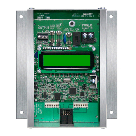
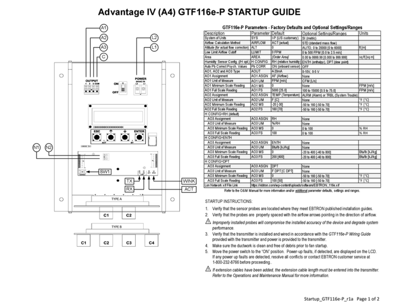
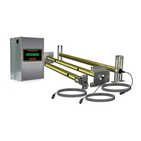
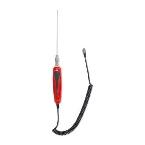
Ebtron GP1 User manual

IG_GPIG_P_INT_R1A
EBTRON, Inc. 1663 Hwy. 701 S., Loris SC 29569
•
Toll Free: 800.2EBTRON (232.8766)
•
Fax: 843.756.1838
• www.
EBTRON.com
GP1/HP1/SP1 DUCT & PLENEM PROBES - INTERNAL
M
OUNT
QUICK INSTALLA
T
ION
G
UIDE
a measurable difference!
EBTRON
®
1
GP1, HP1 AND SP1
DUCT AND PLENUM PROBE
INTERNAL MOUNT INSTALLATION
OVERVIEW
This document provides the instructions necessary
to install Internal Mount Probes as shown in Figure
1. Internally mounted probes are installed inside of
the duct/plenum. Internal mounting is ideal for
applications where access through the outside of
the duct is limited or not possible and is also well
suited for installation in air handling units and
plenums. Installation consists of marking the duct
for bracket installation and then securing the probe
mounting
brackets. For detailed probe information, refer to
the Duct/Plenum Probe technical manual under
separate cover. For detailed information on
transmitter set up and operation of the complete
airflow measurement station, refer to the
associated transmitter technical manual under
separate cover. Observe the following installation
precautions:
CAUTION
Location of the probe(s) is critical for proper performance of the airflow station. Probes
must be installed in accordance with the engineer’s plans and EBTRON Minimum
Placement Guidelines (Figures 4 and 5) for the specified location. For additional probe
placement detail, refer to the probe technical manual under separate cover.
Ensure that adequate installation/service clearance exists at the installation site to
permit installation of the probe into the duct/plenum, and that the cable length for the
probes is sufficient to reach the planned transmitter installation. Refer to the mechanical
details of Figure 2.
On applications where multiple probes are to be installed at a single measurement
location, install probes in accordance with Figure 3 (Internal Mount Probe
Spacing/Configuration). In addition, when traverse data is desired (Gold Series GP1
probes only), place the lowest numbered probe at the top of the duct for horizontal
mounting. For vertical mounting, place the lowest numbered probe on the left side of
duct when viewed from the upstream side of the mounting location, with cables exiting on
the higher side to prevent any potential moisture from accumulating on the heated
sensors.
Insulation that may interfere with mounting should be temporarily removed prior to
installation and replaced afterwards.
INTERNAL MOUNTING OVERVIEW
Figure 2 provides Standard Internal Mount probe installation details. Probes are installed from inside of
the duct or plenum using the included brackets. Internal insulation that may interfere with mounting
should be temporarily removed to permit installation. Internal mount probes are manufactured shorter to
permit 0.75 in (19 mm) adjustment and allow for installation clearance. Install each probe as follows
using the convenient check boxes at each step.
Fi
g
ure 1.
Internal Mount Probe
Document
Number 930-0035

IG_GPIG_P_INT_R1A
EBTRON, Inc. 1663 Hwy. 701 S., Loris SC 29569
•
Toll Free: 800.2EBTRON (232.8766)
•
Fax: 843.756.1838
• www.
EBTRON.com
GP1/HP1/SP1 DUCT & PLENEM PROBES - INTERNAL
M
OUNT
QUICK INSTALLA
T
ION
G
UIDE
a measurable difference!
EBTRON
®
2
INTERNAL MOUNT MARKING AND PREPARATION
1. Each probe package is factory labeled for the specific location and duct size for which it is designed.
Orders for locations requiring multiple probes at a specific location are typically banded and packaged together.
Determine the specific duct location for the probe(s) as indicated on the engineer's plans showing where the
airflow measuring station is to be located. Refer to Figure 3 for probe spacing and orientation.
2. Carefully open the probe packaging and inspect for damage. Proceed to the specific additional installation
instructions for rectangular ducts (at step 3), round ducts (at step 6) or flat oval duct applications (at step 9).
For Rectangular Ducts
3. The first dimension of the probe size indicates the length of the probe. The second dimension indicates
the specific duct internal mounting inside dimension 'X' (including internal insulation). On ducts with internal
insulation that cannot be removed, adjust ‘X’ to equal the internal mounting inside dimension, minus two times
the thickness of the insulation. Refer to Figure 2 and verify that the probe is the correct size for the application
duct size. Mark a point on the center of the inside of the duct at ‘X’. Draw a line on the inside of the duct at this
point that is perpendicular to the edge of the duct. This line will be used to locate the position of the probe
mounting brackets. The probe quantity for the measurement site determines the probe installation
configuration/orientation as shown in Figure 3.
4. Using the applicable Rectangular Duct Probe mechanical and spacing details of Figures 2 and 3, mark
the location for the cable exit end of each probe bracket at the location line(s) drawn in step 3.
5. Mark the other corresponding end bracket (without cable) installation locations for each probe at the
opposite side of the inside duct wall.
Proceed to step 12, Final Assembly.
For Round Ducts
6. Mark and draw a line around the inside circumference of the duct at the point where the probe brackets
are to be installed. The number of probes for this specific measurement site determines the probe installation
configuration and orientation as shown in Figure 3. Applications with multiple probes must be staggered 1.5 to
2 in (38.1 to 50.8 mm) from each other as shown in Round Duct Probe Spacing detail of Figure 4 to prevent
probes from intersecting at the center of the duct.
7. Using the Round Duct Probe Spacing detail of Figure 3, locate and mark the individual probe
mounting location(s) on the circumference line drawn in step 6.
8. Mark the non cable end bracket installation locations for each probe on the opposite side of the inside
duct wall.
Proceed to step 12, Final Assembly.
For Flat Oval Ducts
9. Mark and draw a line around the inside circumference of the duct at the point where the probes are to
be installed. For oval duct applications, orientation is as shown in the Oval Duct Probe Spacing table and detail
application illustrations of Figure 3. Configuration ‘2b’, ‘3b’ and ‘4b’ probes must be staggered 1.5 to 2 in (38.1
to 50.8 mm) from each other in order to prevent probes from intersecting at the center of the duct.
10.Using the Round Duct Probe Spacing detail of Figure 3, locate and mark the individual probe installation
location(s) for the cable exit end of each probe bracket on the circumference line drawn in step 6.
11.Mark the non cable end bracket installation locations for each probe on the opposite side of the inside duct
wall.
Proceed to step 12, Final Assembly.

IG_GPIG_P_INT_R1A
EBTRON, Inc. 1663 Hwy. 701 S., Loris SC 29569
•
Toll Free: 800.2EBTRON (232.8766)
•
Fax: 843.756.1838
• www.
EBTRON.com
GP1/HP1/SP1 DUCT & PLENEM PROBES - INTERNAL
M
OUNT
QUICK INSTALLA
T
ION
G
UIDE
a measurable difference!
EBTRON
®
3
FINAL ASSEMBLY FOR STANDARD PROBES
12. Ensure that provision has been made for an appropriate cable exit hole through the duct/plenum. The cable
exit hole must be of sufficient size to pass the probe connector (which is approximately 0.85 in [20.8 mm]) PLUS
any other cables planned for this exit hole. The edges of the cable exit hole must be prepared to ensure that no
damage occurs to cable or insulating jacket during or after installation.
13. Loosen the Non-Cable End Adjustment Screws on both sides of the probe as shown in the detail of Figure 2
for Standard Probes to permit pivoting the probe and bracket.
14. Carefully place the non-cable end bracket at the non cable end marked location on the inside of the duct
wall so that when the probe is installed, airflow will be in the direction of the arrows printed on the bracket and/or
probe. For ease of installation, the probe can pivot within the bracket after loosening the non-cable end Adjustment
Screws (completed in step 13).
NOTE:
If the airflow direction labels are not visible on the bracket and/or probe, orient the probe so
that the sensor SET SCREWS (two per sensor insert) face the DOWNSTREAM side of the
probe as shown in Figure 2. (There are no setscrews on the upstream side of the sensor
inserts).
15. Fasten the Non-Cable End mounting bracket to the duct at two places with appropriate field supplied
fasteners, again making sure that printed airflow arrows on the bracket and/or probe are in the actual direction of
duct air flow.
16. Carefully route the probe cable through the cable exit hole prepared in step 12, and pivot the cable end
probe bracket to the marked location on the duct wall.
17. Fasten the cable end mounting bracket to the duct at two places with appropriate field supplied fasteners,
again making sure that printed airflow arrows on the bracket and/or probe are in the actual direction of duct air
flow.
18. Slightly loosen the cable end probe Adjustment screws on both sides of the probe to permit probe movement
within the bracket.
19. Carefully center the probe in the duct opening, and then tighten the probe Adjustment Screws on both sides
of the cable end bracket, and then on both sides of the non-cable end bracket as shown in Figure 2 detail. (There
are 4 Adjustment Screws total).
20. Repeat steps 12 through 19 for all probes.
21. Seal all cable exit holes with suitable sealant material.
22. Connect all sensor probes to the transmitter supplied for the specific location. This completes probe
installation.
Complete the installation, wiring and set up of the associated transmitter as detailed in the separate Transmitter
Installation Guide and the Installation, Operation and Maintenance Technical Manual (each provided under
separate cover).

IG_GPIG_P_INT_R1A
EBTRON, Inc. 1663 Hwy. 701 S., Loris SC 29569
•
Toll Free: 800.2EBTRON (232.8766)
•
Fax: 843.756.1838
• www.
EBTRON.com
GP1/HP1/SP1 DUCT & PLENEM PROBES - INTERNAL
M
OUNT
QUICK INSTALLA
T
ION
G
UIDE
a measurable difference!
EBTRON
®
4
Figure 2. Standard Internal Mount Probe Mechanical Detail
• • •
FINAL ASSEMBLY FOR STANDARD PROBES*
* Note: The following instructions apply to Standard probes. For AIR IQ Probes, see separate
AIR IQ FINAL ASSEMBLY instructions that follow, and refer to Figure 3.
NOTE:
3.75 in. (95.25 mm)
5.25 in. (133.35 mm)
1.50 in.
38.10 mm
Overall Duct Size
(including internal insulation)
Gasket Gasket
4.00 in.
(101.60 mm)
Washer
Lock nut
0.375 in. (9.52 mm) x 1.50 in. (38.1 mm) Stud
Insertion side bracket
Terminal end bracket
1.00 in.
(25.4 mm)
0.75 in.
(19.05 mm)
1.1 in. (27.94 mm) dia. tube
[8.00 in. (203.20 mm) to 192.00 in. ( 4876.80 mm) long]
0.75 in. ( 19.05 mm) dia. sensor opening
1 to 4 sensors/probe
Cable
0.188 in. (4.78 mm)
Mtg. Holes (4)
5.25 in. (133.35 mm)
Airflow
Insertion Side Bracket
0.375 in. (9.53 mm)
1/2 in (12.70 mm)
0.50 in. (12.70 mm)
4.00 in (101.60 mm)
4 in (101.60 mm)
Terminal End Bracket
0.375 in.
(9.53 mm)
0.75 in. (19.05 mm)
5.25 in. (133.35 mm)
0.188 in. (4.78 mm)
Mtg. Holes (4)
Figure 2. Standard Insertion Mount Probe Mechanical Detail
NOTE:
Set
-s
screws
f
for
s
sensor
i
inserts
o
on
p
probes
m
must
a
always
f
face
d
downstream
i
in
a
airflow.
STANDARD
P
PROBE
INSERTION
M
MOUNT
BRACKET
D
DETAIL
STANDARD
P
PROBE
INSERTION
M
MOUNT
INSTALL
D
DETAIL
Mounting
S
Screws
8
8
R
Req’d
(4/ Bracket
F
Field
S
Supplied)
P
R
E
S
S
NOTE:
Probes under 18 in (45 7.2
mm) are not equipped with
the terminal end bracket,
and therefore do not require
a mounting hole on the
opposite side of the duct.
1 to 8 sensors per probe

IG_GPIG_P_INT_R1A
EBTRON, Inc. 1663 Hwy. 701 S., Loris SC 29569
•
Toll Free: 800.2EBTRON (232.8766)
•
Fax: 843.756.1838
• www.
EBTRON.com
GP1/HP1/SP1 DUCT & PLENEM PROBES - INTERNAL
M
OUNT
QUICK INSTALLA
T
ION
G
UIDE
a measurable difference!
EBTRON
®
5
Figure 3. Internal
Mount
Probe
Spacing/Configuration
• • •
2b
2 PROBE OVAL
2c
2 PROBE OVAL
3b
3 PROBE ROUND
One Probe Two Probes Three Probes Four Probes
RECTANGULAR
D
DUCT
P
PROBE
S
SPACING
ROUND
D
DUCT
P
PROBE
S
SPACING
OVAL
D
DUCT
P
PROBE
S
SPACING
Select
c
configuration
d
diagram
f
from
t
table
b
based
u
upon
p
probe
l
length/duct
s
size
a
and
s
sensor
d
density
Figure 4. Insertion Mount Probe Spacing/Configuration
DCBADCBADCBADCBADCBADCBADCBADCBADCBADCBADCBADCBADCBADCBADCBA
1
1
2
2
2b 2b 2c 2c 2c 3c 3c 3c 3c 3c 3c 4c 4c
1
1
8
8
2b 2b 2b 2b 2c 2c 2c 2c 3c 3c 4c
2
2
4
4
2b 2b 3c 2b 3c
3
3
0
0
1a 1a 1a 1a 1a 2b 3c 2b 1a 2b 3c 2b 1a
3
3
6
6
3b 1a 1a 1a 1a 1a 1a
4
4
2
2
1a 2b 1a 1a 1a 1a 1a 1a 1a 1a 1a
4
4
8
8
4b 3b 2b 1a 1a 1a 1a 1a 1a 1a 1a 1a
5
5
4
4
4b 3b 2b 1a 1a 1a 1a 1a 1a 1a 1a
6
6
0
0
2b 1a 1a 1a 1a 1a 1a 1a
6
6
6
6
2b 1a 1a 1a 1a 1a 1a
7
7
2
2
2b 1a 1a 1a 1a 1a
8
8
4
4
2b 1a 1a 1a 1a
9
9
6
6
2b 1a 1a 1a
1
1
0
0
8
8
2b 1a 1a
1
1
2
2
0
0
2b 1a
2b
2b
1a
2b
1a 1a
2b 1a 2b 1a
4
4
2
2
4
4
8
8
2b
1a
1a
2b
1a
1a
1a2b
6
6
0
0
6
6
6
6
7
7
2
2
8
8
4
4
9
9
6
6
1
1
2
2
1
1
8
8
2
2
4
4
3
3
0
0
3
3
6
6
2b
2b
1a
1
1
0
0
8
8
1
1
2
2
0
0
1a 1a 1a 1a
5
5
4
4
1a
1a 1a 1a 1a
2b
1a
2b
1a
2b
2b
2b
2b
1a
1a
2b
1a
2b
1a
1a2b
2b
2b
1a 1a
1a 1a
1a
1a
1a
1a4c4c
<- - - - - - - - - - - - - - - - - - - - - - - - - - - - - - - - - - - - - - - - - - - -P
P
R
R
O
O
B
B
E
E
L
L
E
E
N
N
G
G
T
T
H
H
- - - - - - - - - - - - - - - - - - - - - - - - - - - - - - - - - - - - - - - - - - - ->
<- - - - - - - - - A
A
D
D
J
J
A
A
C
C
E
E
N
N
T
T
S
S
I
I
D
D
E
E
L
L
E
E
N
N
G
G
T
T
H
H
- - - - - - - - ->
1a 1a 1a 1a
2b 1a 1a 1a
1a 1a1a
4c 1a
2b 1a 2b 1a 2b 1a
2b 1a
2b 1a 2b 1a 2b 2b 2b
2b 2b
2b 2b
2b 2b 2b 2b 2b 2b 2b
2b 2b 2b 2b 2b 2b 2b
2b 2b 2b 2b 2b 2b
2b 2b
2b
2b 2b 2b 2b 2b 2b
2b 2b
2b
2b 2b 2b 2b 2b
2b 2b
4b
4b
4b
4b
4b
4b
4b
2b 2b 2b
1/4 X 1/2 X 1/4 X
60°
60°
1/2 X
1/2 X
1/4 X
1/2 X
1/4 X
1/6 X
1/3 X
1/3 X
1/6 X
1/8 X
1/4 X
1/4 X
1/4 X
1/8 X
One Probe Two Probes Three Probes Four Probes
90°
60°
60°
90°
45°
1a
1 PROBE OVAL
3c
3 PROBE OVAL
1/6 X 1/3 X 1/3 X 1/6 X
4b
4 PROBE ROUND
90°
45°
4c
4 PROBE OVAL
1/8 X 1/4 X 1/4 X 1/4 X 1/8 X
This manual suits for next models
2
Other Ebtron Measuring Instrument manuals
Popular Measuring Instrument manuals by other brands
Herholdt Controls
Herholdt Controls ECS1-125 Installation and operating instructions

Bürkert
Bürkert 8222 ELEMENT NEUTRINO operating instructions

Endress+Hauser
Endress+Hauser Proline Prosonic Flow 92F Series Safety instructions

Thermo Scientific
Thermo Scientific TSQ 9610 Hardware manual

Joinwit
Joinwit JW3209 Series manual
Emerson
Emerson Daniel Senior Orifice Fitting Series Owner's and operator's manual
