EXFO FOT-5200 User manual

User Guide
CWDM Analyzer
FOT-5200

ii FOT-5200
Copyright © 2010–2011 EXFO Inc. All rights reserved. No part of this
publication may be reproduced, stored in a retrieval system or transmitted
in any form, be it electronically, mechanically, or by any other means such
as photocopying, recording or otherwise, without the prior written
permission of EXFO Inc. (EXFO).
Information provided by EXFO is believed to be accurate and reliable.
However, no responsibility is assumed by EXFO for its use nor for any
infringements of patents or other rights of third parties that may result from
its use. No license is granted by implication or otherwise under any patent
rights of EXFO.
EXFO’s Commerce And Government Entities (CAGE) code under the North
Atlantic Treaty Organization (NATO) is 0L8C3.
The information contained in this publication is subject to change without
notice.
Trademarks
EXFO’s trademarks have been identified as such. However, the presence
or absence of such identification does not affect the legal status of any
trademark.
Units of Measurement
Units of measurement in this publication conform to SI standards and
practices.
Version number: 2.0.0

Contents
CWDM Analyzer iii
Contents
Certification Information ........................................................................................................v
1 Introducing the FOT-5200 CWDM Analyzer ................................................. 1
Main Functions .......................................................................................................................3
Conventions ............................................................................................................................4
2 Safety Information ....................................................................................... 5
Battery Charger .......................................................................................................................6
3 Setting Up and Operating your FOT-5200 ................................................... 9
Cleaning and Connecting Optical Fibers .................................................................................9
Turning Unit On and Off .......................................................................................................10
Menu Tree .............................................................................................................................11
User Specification (CWDM SCAN) .........................................................................................16
Scanning All Channels (ALL SCAN) ........................................................................................18
Finding Relative Value (dB) of All Channels ...........................................................................19
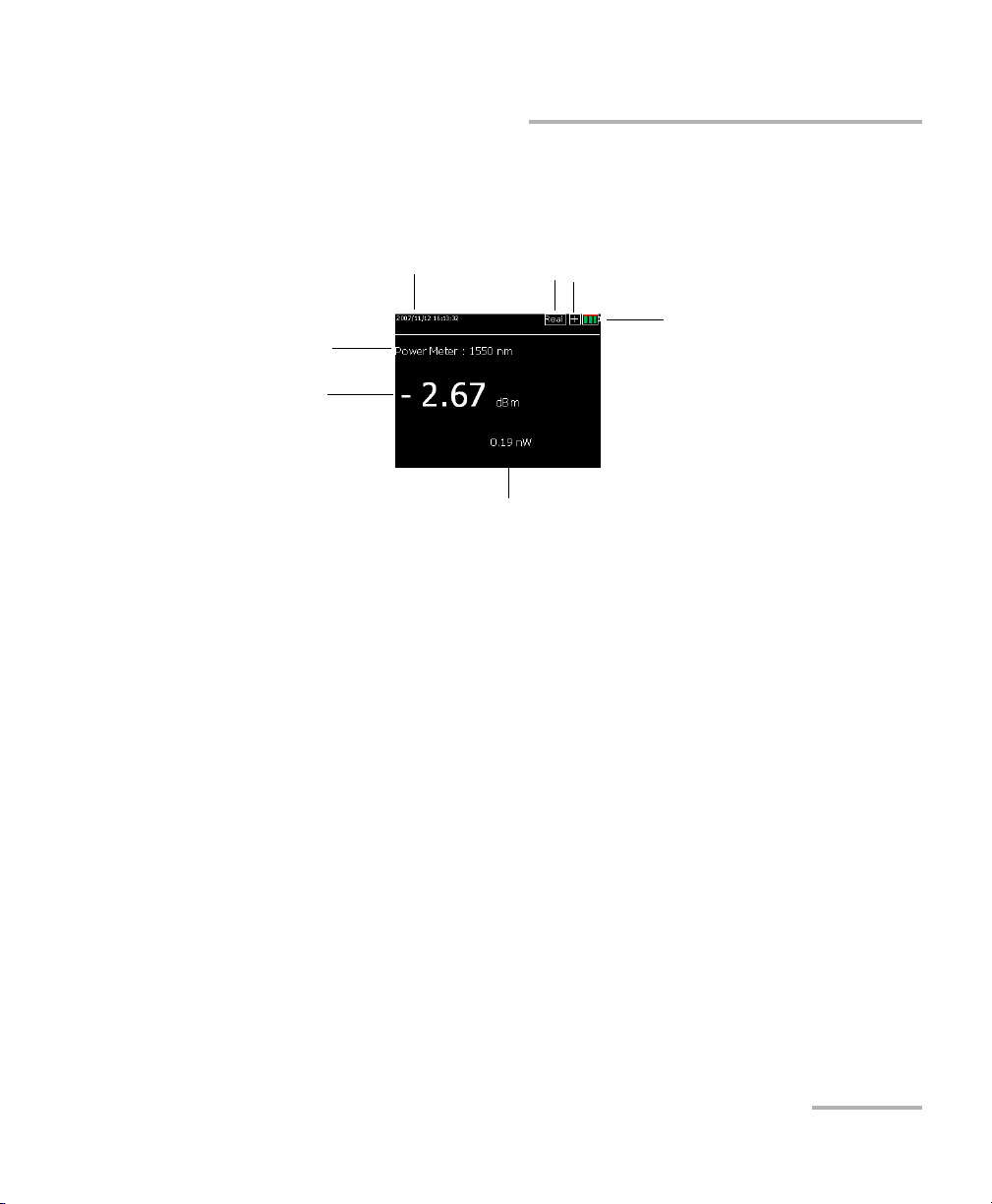
General Power Meter ............................................................................................................20
dB/dBm .................................................................................................................................21
Graph Data Display ...............................................................................................................22
Saving Information and Naming Files ...................................................................................23
Opening Files ........................................................................................................................24
4 Maintenance ............................................................................................... 25
Cleaning Detector Ports ........................................................................................................26
Recalibrating the Unit ...........................................................................................................27
Recycling and Disposal (Applies to European Union Only) ....................................................27
5 Troubleshooting ......................................................................................... 29
Solving Common Problems ...................................................................................................29
Contacting the Technical Support Group ..............................................................................29
Viewing System Information .................................................................................................30
Transportation ......................................................................................................................30

Contents
iv FOT-5200
6 Warranty ......................................................................................................31
General Information .............................................................................................................31
Liability .................................................................................................................................32
Exclusions .............................................................................................................................33
Certification ..........................................................................................................................33
Service and Repairs ...............................................................................................................34
EXFO Service Centers Worldwide ..........................................................................................35
A Technical Specifications ..............................................................................37

Certification Information
CWDM Analyzer v
Certification Information
Federal Communications Commission (FCC) and
Industry Canada Information
Electronic test and measurement equipment is exempt from FCC part 15,
subpart B compliance in the United States of America and from ICES-003
compliance in Canada. However, EXFO Inc. makes reasonable efforts to
ensure compliance to the applicable standards.
The limits set by these standards are designed to provide reasonable
protection against harmful interference when the equipment is operated in
a commercial environment. This equipment generates, uses, and can
radiate radio frequency energy and, if not installed and used in accordance
with the user guide, may cause harmful interference to radio
communications. Operation of this equipment in a residential area is likely
to cause harmful interference in which case the user will be required to
correct the interference at his own expense.
Modifications not expressly approved by the manufacturer could void the
user's authority to operate the equipment.
Information
Electronic test equipment is subject to the EMC Directive in the European
Union. The IEC 61326-1 standard prescribes both emission and immunity
requirements for laboratory, measurement, and control equipment.
This unit has undergone extensive testing according to the European Union
Directive and Standards.

Certification Information
vi FOT-5200
DECLARATION OF CONFORMITY
Application of Council Directive(s):
2006/95/EC –The Low Voltage Directive
2004/108/EC –The EMC Directive
93/68/EEC –CE Marking
And their amendments
Manufacturer’s Name and Address:
EXFO Inc. EXFO Europe
400 Godin Avenue Omega Enterprise Park, Electron Way
Quebec City, Quebec Chandlers Ford, Hampshire
G1M 2K2 CANADA SO53 4SE ENGLAND
Tel.: +1 418 683-0211 Tel.: +44 2380 246810
Equipment Type/Environment:
Test & Measurement / Industrial
Trade Name/Model No.:
CWDM ANALYZER / FOT-5200
Standard(s) to which Conformity is declared:
EN 61010-1:2001 Edition 2.0
Safety requirements for electrical equipment for measurement,
control, and
laboratory use –Part 1: General requirements
EN 61326-1:2006
Electrical equipment for measurement, control and laboratory use –
EMC requirements
–Part 1: General requirements
EN 60825-1:2007 Edition 2.0
Safety of laser products –Part 1: Equipment classification and
requirements
I, the undersigned, hereby declare that the equipment specified above conforms to the above Directive and Standards.
Manufacturer:
Stephen Bull, E. Eng
Vice-President Research and Development
400 Godin Avenue,
Quebec City, Quebec
G1M 2K2 CANADA
August 18, 2010

CWDM Analyzer 1
1 Introducing the FOT-5200
CWDM Analyzer
The FOT-5200 CWDM Analyzer is designed to measure and mark
wavelengths in order to measure the exact power independently for each
coarse wavelength division multilplexing (CWDM) channel. This
instrument is portable and made to be appropriate to the outside
environment.
When using a broadband powermeter, only the total optical power of the
combined CWDM channels can be measured. When several wavelengths
are sent at once, the exact value of each wavelength cannot be measured.
Thus for CWDM, which functions over several wavelengths, a device that
can distinguish the wavelengths must be used.
The FOT-5200 is developed to measure exact power and is adaptable to
the various network conditions. It is especially suitable for outer
environments and is compact, therefore easy to carry.

Introducing the FOT-5200 CWDM Analyzer
2FOT-5200
The picture below shows the FOT-5200, and the usage of the keypad
essential in operating the measuring instrument.
Display
Optical port
Power key
Escape key
Enter key
Arrow keys
Charging and data
communication port
Open file key
Menu key
All scan key
User scan key
View mode key
Power meter key
CWDM scan key

Introducing the FOT-5200 CWDM Analyzer
CWDM Analyzer 3
Main Functions
The picture below shows the display screen when measuring a single
channel.
Main Functions
Simultaneous measurement of optical power in all channels in a single
scan, which is the key factor in the field of installation, maintenance
and repair.
Works as a broadband power meter and as a loss meter.
It is compact in size and lightweight for excellent portability.
Can use the existing charger and USB Data Communication Cable by
using a typical cell phone 24-pin connector
Features a color LCD
Sorts measured data
Saves/Reads measured data
Displays measured time
Date and time
Channel mode
Current
channel power
Current
measurement
mode
Power unit
Battery level
Optical module detection status
(shows X if not detected)

Introducing the FOT-5200 CWDM Analyzer
4FOT-5200
Conventions
Conventions
Before using the product described in this guide, you should understand
the following conventions:
WARNING
Indicates a potentially hazardous situation which, if not avoided,
could result in death or serious injury. Do not proceed unless you
understand and meet the required conditions.
CAUTION
Indicates a potentially hazardous situation which, if not avoided,
may result in minor or moderate injury. Do not proceed unless you
understand and meet the required conditions.
CAUTION
Indicates a potentially hazardous situation which, if not avoided,
may result in component damage. Do not proceed unless you
understand and meet the required conditions.
IMPORTANT
Refers to information about this product you should not overlook.

CWDM Analyzer 5
2 Safety Information
To prevent fire or injury:
Use an appropriate battery. Use only a battery approved for the
product.
Connect and disconnect the battery properly.
Do not disconnect the battery when the product is on.
Check the patchcord standard. Use the appropriate type of connector
for the product to prevent damage of connector or error of measured
value by checking whether the adaptor type is right for the connector
at time of purchase.
Follow all connector standards. To avoid damage or shock of product,
follow all instructions for connectors and product. Refer to the product
manual before connecting the product and check additional
information on adaptor.
WARNING
Do not install or terminate fibers while a light source is active.
Never look directly into a live fiber and ensure that your eyes are
protected at all times.
WARNING
Use of controls, adjustments and procedures for operation and
maintenance other than those specified herein may result in
hazardous radiation exposure or impair the protection provided by
this unit.
IMPORTANT
When you see the following symbol on your unit , make sure
that you refer to the instructions provided in your user
documentation. Ensure that you understand and meet the required
conditions before using your product.

Safety Information
6FOT-5200
Battery Charger
Turn off the product’s power using the Power button.
Do not operate the product with the cover removed.
Do not operate a product suspected of being damaged. Have it
checked by a certified professional technician.
Do not touch exposed circuits. Do not touch exposed connections or
parts when power is being supplied.
Do not use in damp environments.
Keep the surface of product clean and dry.
Battery Charger
A rechargeable battery is installed inside the measuring instrument, and
this charger module has a standard 24-pin charger port.
When the charger module is connected to the measuring instrument, the
circular picture on the connecting part points to the bottom of the
instrument.
The LED on the charger module indicates different situations depending on
its color and state:
Color Status
Red, ON (continuous) The charger module is in charging
mode.
Green, ON (continuous) Charge complete. Ready to use.
Red, Blinking Error or damage to battery.

Safety Information
CWDM Analyzer 7
Battery Charger
Here are additional precautions pertaining to battery use:
Charging time is about five hours. If the indicating lamp has changed
add one more hour.
Do not allow battery to short circuit.
Keep the battery away from fire. There is danger of explosion when the
battery is near fire.
Never dismantle, change structure or distort the battery. See on
page 27 for more information.
Do not dip the battery in water or other liquids.
Do not store the battery in places warmer than 40 degrees Celsius.
Do not drop or give a shock to the battery.
Ensure the battery is oriented correctly.
Power of charger is 110~220V at 50/60 Hz.
Remove the battery when it is not in use for a long time.


CWDM Analyzer 9
3 Setting Up and Operating
your FOT-5200
Cleaning and Connecting Optical Fibers
To connect the fiber-optic cable to the port:
1. Inspect the fiber using a fiber inspection microscope. If the fiber is
clean, proceed to connecting it to the port. If the fiber is dirty, clean it as
explained below.
2. Clean the fiber ends as follows:
2a. Gently wipe the fiber end with a lint-free swab dipped in isopropyl
alcohol.
2b. Use compressed air to dry completely.
2c. Visually inspect the fiber end to ensure its cleanliness.
IMPORTANT
To ensure maximum power and to avoid erroneous readings:
Always inspect fiber ends and make sure that they are clean as
explained below before inserting them into the port. EXFO is
not responsible for damage or errors caused by bad fiber
cleaning or handling.
Ensure that your patchcord has appropriate connectors. Joining
mismatched connectors will damage the ferrules.

Setting Up and Operating your FOT-5200
10 FOT-5200
Turning Unit On and Off
3. Carefully align the connector and port to prevent the fiber end from
touching the outside of the port or rubbing against other surfaces.
If your connector features a key, ensure that it is fully fitted into the
port’s corresponding notch.
4. Push the connector in so that the fiber-optic cable is firmly in place,
thus ensuring adequate contact.
If your connector features a screwsleeve, tighten the connector
enough to firmly maintain the fiber in place. Do not overtighten, as this
will damage the fiber and the port.
Note: If your fiber-optic cable is not properly aligned and/or connected, you will
notice heavy loss and reflection.
Turning Unit On and Off
The Power button ( ) is used to turn the unit on and off.
If you press Power for more than 1.5
seconds, the logo appears and the unit
beeps. It then moves to Total Power,
which is the basic channel.
Press Power for more than two seconds
to turn the power off.
To adjust LCD Back Light:
It is possible to adjust the brightness of
LCD's back light to one of two levels by
pressing Power for just a short time.

Setting Up and Operating your FOT-5200
CWDM Analyzer 11
Menu Tree
Menu Tree
If you press MENU ( ), it changes
to a screen where you can configure the
operating environment of FOT-5200 and
set up calibration, special operations,
etc.
The menu includes the features below:
Note: Malfunction of the FOT-5200 can occur due to incorrect setup of functions.
Item Description
USER SCAN User defined channels
OFFSET (VOLATILE) Offset function
USB, RS232 C BAUDRATE Establishes communication
speed
AUTO POWER OFF Setup for auto-off feature
KEY LIGHT OFF Manages lighting of keypad
FILE SYSTEM Functions for file
management
SET TIME To set time and date.
SYSINFO Information on equipment
CALIBRATION EXFO use only.

Setting Up and Operating your FOT-5200
12 FOT-5200
Menu Tree
User-Defined Channels (USER SCAN)
USER SCAN ( ) is a button assigned to scan only channels defined by
the user.
To set up USER SCAN:
1. Press MENU to change to the menu screen.
2. Use the arrow buttons to select
USER SCAN, then press ENT.
As the channel values that users
mainly use are provided in the
above screen, it is easy to set up the
channel value that you want.
3. If you press ENT after selecting
USER SELECT, you can select the
channel that you want. If you then
press ENT, it changes from OFF to ON.
The set up value is automatically saved
if you come out using the ESC key after
finishing channel selection.
Note: The measurement time depends on the
number of channels selected. Choosing
the correct channels to be measured
minimizes measurement time.
Mobile telecommunication companies
use 1310, 1550 nm for 2 G optic wavelengths and 1510, 1530, 1570 nm for
3 G optic wavelengths. Thus you should set up the user channel to (1310,
1510, 1530, 1550, 1570) in the menu.

Setting Up and Operating your FOT-5200
CWDM Analyzer 13
Menu Tree
When you press Graph/TEXT ( ) after performing a scan with the
USER SCAN button, you can see a user scan graph screen such as the
following.
OFFSET (VOLATILE)
The OFFSET function displays the
addition of set up dBm value and the
optic power value on the screen.
The user can increase reliability and
continuously maintain the measuring
instrument's own features and settings
by synchronizing the output value with
other measuring instruments using the
calibration function for each channel.
Note: As this value is saved in the volatile memory, it becomes zero after booting
and is not remembered if you turn the power off after set up.
User Channel Text Mode User Channel Graph Mode

Setting Up and Operating your FOT-5200
14 FOT-5200
Menu Tree
Communication Speed Set Up (USB, RS-232C,
Baudrate)
If you press the arrow keys in USB
RS232C Baudrate, you can set up the
transmission speed of the COM Port, and
the default value is 115200 bps.
Power management Set Up (Auto Power)
The power automatically goes off if the
user does not press a key in the
determined time.
You can activate or de-activate the
option by pressing ENT and set the time
in minutes using the arrow keys.
LED Management Set Up
(KEYPAD LIGHT OFF)
This is a function to set up power
management of the FOT-5200 like Auto
Power.
The lighting goes off if the user does not
press a key during the determined time.
You can activate and de-activate the
option by pressing ENT, and set up the
time in seconds by using the arrow keys.
Table of contents
Other EXFO Measuring Instrument manuals

EXFO
EXFO PM-1100 User manual

EXFO
EXFO USER GUIDE User manual

EXFO
EXFO FLS-2600B User manual

EXFO
EXFO R5000 User manual

EXFO
EXFO T100S-HP Series User manual

EXFO
EXFO T200S User manual

EXFO
EXFO FTB-5600 User manual

EXFO
EXFO FLS-5834A User manual

EXFO
EXFO FOT-10A User manual

EXFO
EXFO FTB-740 DWOCC Series User manual

EXFO
EXFO T100S-HP Series Operating instructions

EXFO
EXFO IQS-2400 User manual

EXFO
EXFO LTB-12 User manual

EXFO
EXFO IQS-12008 User manual

EXFO
EXFO FTB-5700 User manual

EXFO
EXFO FTB-5230S User manual

EXFO
EXFO PMD Analyzer 5500B User manual

EXFO
EXFO T500S User manual

EXFO
EXFO FTB-2 Operation and maintenance manual

EXFO
EXFO FLS-2200 User manual