LD XECI User manual

USER´S MANUAL / BEDIENUNGSANLEITUNG /
MANUEL D´UTILISATION / MANUAL DE USUARIO /
INSTRUKCJA OBSŁUGI / MANUALE D´USO
XECI
ETHERNET CONTROL INTERFACE CARD FOR IPA SERIES
LDXECI

CONTENTS / INHALTSVERZEICHNIS / CONTENU / CONTENIDO / TREŚĆ / CONTENUTO
ENGLISH
INFORMATION ON THIS QUICK GUIDE 4
PRODUCT INFORMATION 4
SAFETY INSTRUCTIONS 4
SCOPE OF DELIVERY 5
ASSEMBLY 5
CONNECTIONS, CONTROLS AND INDICATORS 6
NETWORK CONNECTION 6
TECHNICAL DATA 9
DISPOSAL 10
MANUFACTURER´S DECLARATIONS 11
DEUTSCH
INFORMATIONEN ZU DIESER KURZANLEITUNG 12
PRODUKTINFORMATIONEN 12
SICHERHEITSHINWEISE 12
VERPACKUNGSINHALT 13
MONTAGE 13
ANSCHLÜSSE, BEDIENELEMENTE UND ANZEIGEN 14
NETZWERKVERBINDUNG 15
TECHNISCHE DATEN 17
ENTSORGUNG 18
ERKLÄRUNGEN DES HERSTELLERS 19
FRANÇAIS
INFORMATIONS SUR CE GUIDE RAPIDE 20
INFORMATIONS SUR LE PRODUIT 20
CONSIGNES DE SÉCURITÉ 20
CONTENU DU CARTON 21
ASSEMBLY 21
CONNECTIONS, CONTROLS AND INDICATORS 22
CONNEXION RÉSEAU 22
CARACTÉRISTIQUES TECHNIQUES 25
MISE EN DÉCHETTERIE 26
DÉCLARATIONS DU FABRICANT 27

ESPAÑOL
INFORMACIÓN EN ESTA GUÍA RÁPIDA 28
INFORMACIÓN DEL PRODUCTO 28
INSTRUCCIONES DE SEGURIDAD 28
CONTENIDO DE LA ENTREGA 29
MONTAJE 29
CONEXIONES, CONTROLES E INDICADORES 30
CONEXIÓN A LA RED 31
DATOS TÉCNICOS 33
ÉLIMINATION 34
DECLARACIONES DEL FABRICANTE 35
POLSKI
INFORMACJE ZAWARTE W TYM SKRÓCONYM PRZEWODNIKU 36
INFORMACJE O PRODUKCIE 36
INSTRUKCJE BEZPIECZEŃSTWA 36
ZAKRES DOSTAWY 37
MONTAŻ 37
POŁĄCZENIA, ELEMENTY STERUJĄCE I WSKAŹNIKI 38
POŁĄCZENIE SIECIOWE 38
DANE TECHNICZNE 41
DISPOSAL 42
OŚWIADCZENIA PRODUCENTA 43
ITALIANO
INFORMAZIONI SU QUESTA GUIDA RAPIDA 44
INFORMAZIONI SUL PRODOTTO 44
ISTRUZIONI DI SICUREZZA 44
MATERIALE COMPRESO NELLA FORNITURA 45
MONTAGGIO 45
COLLEGAMENTI, CONTROLLI E INDICATORI 46
CONNESSIONE DI RETE 46
DATI TECNICI 49
SMALTIMENTO 50
DICHIARAZIONI DEL PRODUTTORE 51

4
ENGLISH
Expansion module with Ethernet control interface for LD IPA installation
power amplifiers.
INTENDED USE
This item is a product-specific accessory that is only intended for use with the
LD Systems IPA installation power amplifier. These assembly instructions do not
replace the operating instructions for the associated product. Always read the
relevant operating instructions first. This accessory does not affect the intended
use of the associated product. Observe the safety instructions in the operating
instructions for the associated product! The technical data shown in the
operating instructions can change in connection with this accessory item.
SAFETY INSTRUCTIONS
1. Please read these instructions carefully.
2. Keep all information and instructions in a safe place.
3. Follow the instructions.
4. Only use the accessories in the manner intended.
CAUTION: The installation of the expansion module may only be
carried out by qualified personnel. If you are not qualified to do
so, do not attempt to install the extension module yourself, but
use the help of professional companies! Make sure that no foreign
bodies get into the housing!
DANGER: KEEP AWAY FROM CHILDREN! THE PRODUCT CONTAINS SMALL PARTS THAT
CAN BE SWALLOWED AND PACKAGING MATERIAL THAT CAN BE SWALLOWED! PLASTIC
BAGS MUST BE KEPT OUT OF REACH OF CHILDREN!
DEUTSCH FRANÇAIS ESPAÑOLENGLISH ITALIANOPOLSKI

5
SCOPE OF DELIVERY
Remove the product from the packaging and remove all packaging material.
Please check that the delivery is complete and intact and please notify your
distributor immediately after purchase if the delivery is not complete or
damaged. The scope of delivery of the product includes:
• 1x XECI extension module
• Assembly instructions
ASSEMBLY
1. Disconnect the power amplifier completely from the mains
(pull out the mains plug)!
2. Loosen and remove the four screws from the cover of the expansion slot
using a suitable tool (see markings in the illustration). Keep the cover for
later conversion.
3. Slide the expansion module into the expansion slot, making sure that the
contact strip of the module slides correctly into the connection strip of the
power amplifier. Asymmetrically mounted guide pins on the module‘s plate
ensure that the module cannot be installed the wrong way round A.
4. Now screw the module to the power amplifier housing using the screws
previously loosened from the expansion slot cover.
A
A
DEUTSCHFRANÇAIS
ESPAÑOLITALIANO POLSKI ENGLISH

6
CONNECTIONS, CONTROLS AND INDICATORS
Ethernet Card_Artwork_V3_12.07.21
1
23
1ETHERNET
Ethernet interface for controlling the installation amplifier via the free
QUESTRA software.
2STATUS
The status LED provides information about the internal integration between
the card and the main board in the IPA power amplifier (firmware compatibility,
internal communication problems):
• White flashing during start-up. The unit is loading the data for IPA.
• Permanently white: The network stack in the card is ready – The IP settings
have been configured properly.
• Permanent red – Firmware is not compatible with motherboard, problems with
network stack.
• White flashing (slow/fast) during IP reset procedure.
3IP RESET
Long press activates the IP reset procedure. Initially, the status LED flashes
slowly in white and when the button is pressed for 5 seconds, the status LED
flashes quickly to indicate that the IP reset procedure will be carried out after
the button is released.
NETWORK CONNECTION
LD Systems‘ XECI module enables remote control of compatible devices, such
as IPA series amplifiers, over the network. Once the XECI module is built into
a device, it can be connected to a network infrastructure and controlled via
a computer running LD Systems QUESTRA software.
DEUTSCH FRANÇAIS ESPAÑOLENGLISH ITALIANOPOLSKI

7
PREREQUISITES FOR OPERATION
• Computer with QUESTRA software installed
• Network interface (router, switch) with activated multicast traffic
(activate IGMP protocol).
• Ethernet cable. Use a standard RJ45 Ethernet cable (Cat 5e or better)
for all wired connections.
FIRST STEPS
The XECI modules are delivered with a pre-configured static IP address
(192.168.0.192) as standard. To be able to recognise the unit with the Questra
software, please make sure that the IP settings of the computer on which the
Questra software is installed are configured in the same network range as the
XECI modules. See notes below.
• IP range : 192.168.0.X/24 (where X can be any value between 1 and 254,
except 192 which is already used by default by the XECI modules)
• Network mask : 255.255.255.0
DEUTSCHFRANÇAIS
ESPAÑOLITALIANO POLSKI ENGLISH

8
Once a device with a XECI module is connected to a network and switched on,
it will appear under the AVAILABLE DEVICES section in the
ADD DEVICES field on the left. Please note that multicast traffic must be
enabled in the switch/router for the device to be detected.
Drag and drop the device into the PROJECT DEVICES area to be able to configure
it. Then click the Offline button at the top of the screen and select Download
from Devices and connect to connect to the device.
Once the unit is online, click on the unit in the PROJECT
DEVICES list and select the SETTINGS menu on the right to go
directly to the settings menu and change the IP settings of the
unit. For more details about the complete unit configuration
with the QUESTRA software, please download the latest version
from the LD Systems website (www.ld-systems.com)
to your computer and read the user manual.
DEUTSCH FRANÇAIS ESPAÑOLENGLISH ITALIANOPOLSKI

9
QUESTRA SOFTWARE
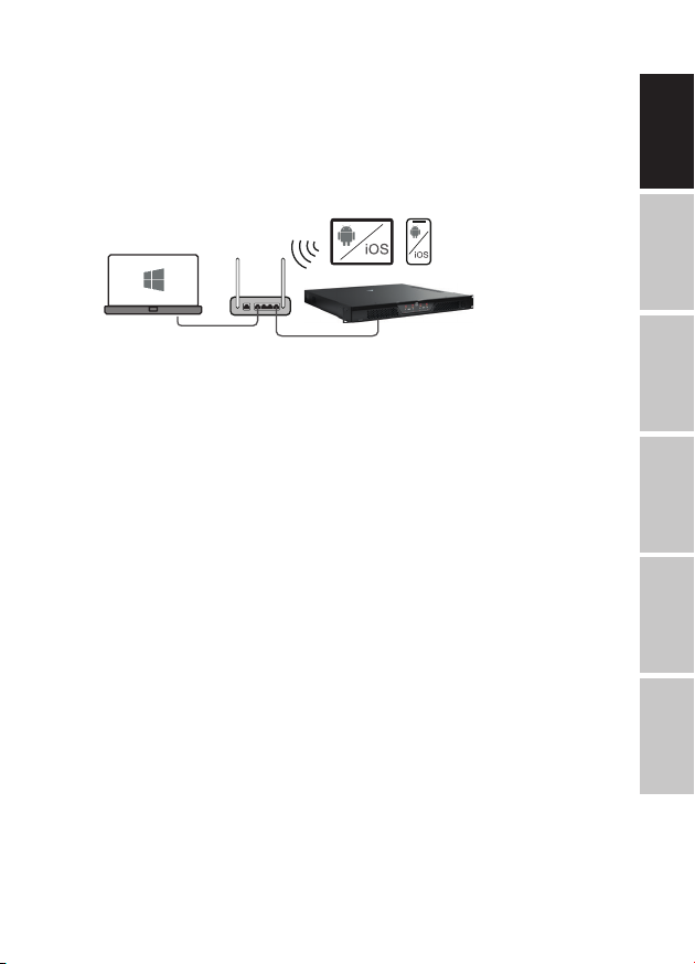
The Questra software not only enables comprehensive configuration of
compatible devices, such as IPA Series amplifiers, but also provides integration
capabilities for third-party remote control units and allows users to create their
own custom control panels that can be controlled via the Questra remote control
apps available for iOS, Android, Windows and MAC OS.
Please download the latest version of the QUESTRA software from the LD Systems
website (www.ld-systems.com) to your computer, check the system requirements
for the software and follow the software instructions to start configuring a unit.
TECHNICAL DATA
Article number LDXECI
Product type Expansion Card to add Ethernet control
Compatibility LD IPA installation power amplifiers
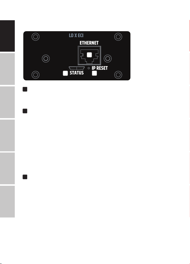
Control element Button for IP reset
Application software QUESTRA (free download)
Display elements RJ45 LEDs: Link / Activity
2-colour LED for internal connection status
Dimensions (W × H × D) 82.5 × 36.5 × 76.3 mm
Weight 50 g
Ethernet
Interface RJ45
Chip STM32H743
Transmission protocol TCP/IP & UDP
Ethernet Standard 10/100 Base-T
Parallel connections 4
Power consumption 1,075 W (Link Down), 1,375 W (Link Up)
Indications
Rear Panel RJ45 LEDs: Link / Activity
Status LED: internal connection status
Software Application
QUESTRA®(free download)
DEUTSCHFRANÇAIS
ESPAÑOLITALIANO POLSKI ENGLISH

10
DISPOSAL
PACKAGING :
1. Packaging can be disposed of via the usual waste
disposal channels.
2. Please separate the packaging according to the waste disposal
and materials regulations in your country.
DEVICE :
1. This device is subject to the European Directive on Waste
Electrical and Electronic Equipment in its applicable version.
WEEE Directive-Waste Electrical and Electronical Equipment. Old
devices and batteries do not belong in household waste. The old
device or batteries must be disposed of via an approved waste
disposal service or a municipal waste disposal facility. Follow the
directives in your country!
2. Follow the disposal laws in your country.
3. As a private customer, you can obtain information on
environmentally friendly disposal options from the retailer
from whom you purchased the product or from the relevant
regional authorities.
DEUTSCH FRANÇAIS ESPAÑOLENGLISH ITALIANOPOLSKI

11
MANUFACTURER´S DECLARATIONS
MANUFACTURER’S WARRANTY & LIMITATION OF LIABILITY
Adam Hall GmbH, Adam-Hall-Str. 1, 61267 Neu Anspach, Germany
Our current warranty conditions and limitation of liability can be found at:
https://cdn-shop.adamhall.com/media/pdf/MANUFACTURERS-DECLARATIONS_LD_SYSTEMS.pdf.
Contact your distribution partner for service.
UKCA-CONFORMITY
Hereby, Adam Hall Ltd. declares that this product meets the following guidelines
(where applicable) Electrical Equipment (Safety) Regulations 2016
Electromagnetic Compatibility Regulations 2016 (SI 2016/1091)
The Restriction of the Use of Certain Hazardous Substances in Electrical
and Electronic Equipment
Regulation 2012 (SI 2012/3032)
Radio Equipment Regulations 201 7(SI 2016/2015)
UKCA-DECLARATION OF CONFORMITY
Products that are subject to Electrical Equipment(Safety)Regulation 2016,
EMC Regulation 2016 or
Products that are subject to the Radio
Equipments Regulations 2017 (SI2017/1206) can be downloaded from
www.adamhall.com/compliance/.
CE CONFORMITY
Adam Hall GmbH hereby confirm that this product meets the following guidelines
(where applicable):
Low-Voltage Directive (2014/35/EU)
EMC Directive (2014/30/EU)
RoHS (2011/65/EU)
RED (2014/53/EU)
CE DECLARATION OF CONFORMITY
Declarations of conformity for products subject to the LVD, EMC, RoHS Directive
Declarations of conformity for products subject to RED can be downloaded from
www.adamhall.com/compliance/.
Misprints and errors as well as technical or other changes are reserved!
DEUTSCHFRANÇAIS
ESPAÑOLITALIANO POLSKI ENGLISH

12
DEUTSCH
Erweiterungsmodul mit Ethernet-Steuerungsschnittstelle für LD IPA
Installationsendstufen.
BESTIMMUNGSGEMÄSSER GEBRAUCH
Bei diesem Artikel handelt es sich um produktspezifisches Zubehör, das
ausschließlich für die Verwendung zusammen mit dem LD Systems IPA
Installationsendstufen vorgesehen ist. Diese Montageanleitung ersetzt nicht
die Bedienungsanleitung des zugehörigen Produkts. Lesen Sie immer zuerst die
entsprechende Bedienungsanleitung. Dieses Zubehör hat keinen Einfluss auf
den bestimmungsgemäßen Gebrauch des zugehörigen Produkts. Beachten Sie
die Sicherheitshinweise aus der Bedienungsanleitung des zugehörigen Produkts!
Die in der Bedienungsanleitung ausgewiesenen technischen Daten können sich
in Verbindung mit diesem Zubehörartikel verändern.
SICHERHEITSHINWEISE
1. Lesen Sie diese Anleitung bitte sorgfältig durch.
2. Bewahren Sie alle Informationen und Anleitungen an einem sicheren Ort auf.
3. Befolgen Sie die Anweisungen.
4. Verwenden Sie das Zubehör nur in der dafür vorgesehenen Art und Weise.
VORSICHT: Die Installation des Erweiterungsmoduls darf nur von
qualifiziertem Personal durchgeführt werden. Wenn Sie dazu nicht
qualifiziert sind, versuchen Sie nicht, das Erweiterungsmodul selbst
zu installieren, sondern nehmen Sie die Hilfe professioneller
Unternehmen in Anspruch! Achten Sie darauf, dass keine
Fremdkörper in das Gehäuse gelangen!
GEFAHR: VON KINDERN FERNHALTEN! DAS PRODUKT ENTHÄLT VERSCHLUCKBARE
KLEINTEILE UND VERSCHLUCKBARES VERPACKUNGSMATERIAL! KUNSTSTOFFBEUTEL
MÜSSEN AUSSER REICHWEITE VON KINDERN AUFBEWAHRT WERDEN!
DEUTSCH FRANÇAIS ESPAÑOLENGLISH ITALIANOPOLSKI

13
VERPACKUNGSINHALT
Nehmen Sie das Produkt aus der Verpackung und entfernen Sie das gesamte
Verpackungsmaterial. Bitte überprüfen Sie die Lieferung auf Vollständigkeit
und Unversehrtheit und informieren Sie Ihren Händler sofort nach dem Kauf,
wenn die Lieferung nicht vollständig oder beschädigt ist. Der Lieferumfang des
Produkts umfasst:
• 1x XECI Erweiterungsmodul
• Montageanleitung
MONTAGE
1. Trenne die Endstufe vollständig vom Netz (ziehe den Netzstecker)!
2. Lösen und entfernen Sie die vier Schrauben der Abdeckung des Erweiter-
ungssteckplatzes mit einem geeigneten Werkzeug (siehe Markierungen in
der Abbildung). Bewahren Sie den Deckel für eine spätere Umwandlung auf.
3. Schieben Sie das Erweiterungsmodul in den Erweiterungssteckplatz und
achten Sie dabei darauf, dass die Kontaktleiste des Moduls richtig in die
Anschlussleiste des Leistungsverstärkers gleitet. Asymmetrisch angebrachte
Führungsstifte auf der Modulplatte sorgen dafür, dass das Modul nicht
verkehrt herum eingebaut werden kann A.
4. Schrauben Sie nun das Modul mit den zuvor gelösten Schrauben von der
Abdeckung des Erweiterungssteckplatzes an das Gehäuse der Endstufe.
A
A
DEUTSCHFRANÇAIS
ESPAÑOLITALIANO POLSKI ENGLISH

14
ANSCHLÜSSE, BEDIENELEMENTE UND ANZEIGEN
Ethernet Card_Artwork_V3_12.07.21
1
23
1ETHERNET
Ethernet-Schnittstelle zur Steuerung des Installationsverstärkers über die
kostenlose QUESTRA-Software.
2STATUS
Die Status-LED gibt Auskunft über die interne Integration zwischen der Karte
und der Hauptplatine im IPA-Endverstärker (Firmware-Kompatibilität, interne
Kommunikationsprobleme):
• Weißes Blinken während des Starts. Die Einheit lädt die Daten für IPA.
• Dauerhaft weiß: Der Netzwerkstack in der Karte ist bereit – Die IP-Einstellungen
wurden ordnungsgemäß konfiguriert.
• Dauerhaft rot – Firmware ist nicht mit dem Motherboard kompatibel,
Probleme mit dem Netzwerkstack.
• Weißes Blinken (langsam/schnell) während des IP-Reset-Vorgangs.
3IP-RESET
Langes Drücken aktiviert die IP-Reset-Prozedur. Zu Beginn blinkt die Status-LED
langsam weiß und wenn Sie die Taste 5 Sekunden lang gedrückt halten, blinkt
die Status-LED schnell, um anzuzeigen, dass der IP-Reset-Vorgang nach dem
Loslassen der Taste durchgeführt wird.
DEUTSCH FRANÇAIS ESPAÑOLENGLISH ITALIANOPOLSKI

15
NETZWERKVERBINDUNG
Das XECI-Modul von LD Systems ermöglicht die Fernsteuerung kompatibler
Geräte, wie z.B. Verstärker der IPA-Serie, über das Netzwerk. Sobald das
XECI-Modul in ein Gerät eingebaut ist, kann es an eine Netzwerkinfrastruktur
angeschlossen und über einen Computer mit der Software LD Systems QUESTRA
gesteuert werden.
VORAUSSETZUNGEN FÜR DEN BETRIEB
• Computer mit installierter QUESTRA-Software
• Netzwerkschnittstelle (Router, Switch) mit aktiviertem Multicast-Verkehr
(IGMP-Protokoll aktivieren).
• Ethernetkabel Verwenden Sie für alle kabelgebundenen Verbindungen ein
standardmäßiges RJ45-Ethernet-Kabel (Cat 5e oder besser).
ERSTE SCHRITTE
Die XECI-Module werden standardmäßig mit einer vorkonfigurierten statischen
IP-Adresse (192.168.0.192) geliefert. Um das Gerät mit der Questra-Software erkennen
zu können, stellen Sie bitte sicher, dass die IP-Einstellungen des Computers, auf
dem die Questra-Software installiert ist, im gleichen Netzwerkbereich wie die
XECI-Module konfiguriert sind. Siehe Anmerkungen unten.
• IP-Bereich : 192.168.0.X/24 (wobei X ein beliebiger Wert zwischen 1 und 254 sein
kann, außer 192, der von den XECI-Modulen bereits standardmäßig verwendet wird)
• Netzwerkmaske : 255.255.255.0
DEUTSCHFRANÇAIS
ESPAÑOLITALIANO POLSKI ENGLISH

16
Sobald ein Gerät mit einem XECI-Modul mit einem Netzwerk an ein Netzwerk
angeschlossen und eingeschaltet ist, erscheint es unter dem Abschnitt
AVAILABLE DEVICES im Feld ADD DEVICES auf der linken Seite. Bitte beachten
Sie, dass der Multicast-Verkehr im Switch/Router aktiviert sein muss, damit das
Gerät erkannt werden kann.
Ziehen Sie das Gerät per Drag & Drop in den Bereich PROJECT DEVICES, um es
konfigurieren zu können. Klicken Sie dann auf die Schaltfläche Offline am oberen
Rand des Bildschirms und wählen Sie Download
from Devices and connect , um dich mit dem Gerät zu verbinden.
Sobald die Einheit online ist, klicken Sie auf die Einheit in der Liste PROJECT
DEVICES und wählen Sie das Menü SETTINGS auf der rechten Seite,
um direkt zum Einstellungsmenü zu gelangen und die IP-Einstellungen
der Einheit zu ändern. Für
weitere Details über die vollständige
Konfiguration der Einheit mit der QUESTRA Software, laden
Sie bitte die neueste Version von der LD Systems Website
(www.ld-systems.com) auf Ihren Computer herunter und
lesen Sie das Benutzerhandbuch.
DEUTSCH FRANÇAIS ESPAÑOLENGLISH ITALIANOPOLSKI

17
QUESTRA-SOFTWARE
Die Questra-Software ermöglicht nicht nur eine umfassende Konfiguration
kompatibler Geräte, wie z. B. der Verstärker der IPA-Serie, sondern bietet auch
Integrationsmöglichkeiten für Fernbedienungseinheiten von Drittanbietern
und ermöglicht es Benutzern, ihre eigenen benutzerdefinierten Bedienfelder zu
erstellen, die über die Questra-Fernbedienungs-Apps gesteuert werden können,
die für iOS, Android, Windows und MAC OS verfügbar sind.
Bitte laden Sie die neueste Version der QUESTRA Software von der LD Systems
Website (www.ld-systems.com) auf Ihren Computer herunter, überprüfen Sie
die Systemanforderungen für die Software und folgen Sie den Anweisungen
der Software, um mit der Konfiguration eines Geräts zu beginnen.
TECHNISCHE DATEN
Artikel Nummer LDXECI
Produkttyp Erweiterungskarte zum Hinzufügen von
Ethernet control
Kompatibilität LD IPA Installations-Leistungsverstärker
Steuerelement Taste für IP-Reset
Abmessungen (B × H × T) 82,5 × 36,5 × 76,3 mm
Gewicht 50 g
Ethernet
Verbindung RJ45
Chip STM32H743
Übertragungsprotokoll TCP/IP & UDP
Ethernet Standard 10/100 Base-T
Parallele Verbindungen 4
Leistungsaufnahme 1,075 W (Link Down), 1,375 W (Link Up)
Indikationen
Rückwand RJ45-LEDs: Link / Activity
Status LED: interner Verbindungsstatus
Software Anwendung
QUESTRA®(kostenloser Download)
DEUTSCHFRANÇAIS
ESPAÑOLITALIANO POLSKI ENGLISH

18
ENTSORGUNG
VERPACKUNG :
1. Verpackungen können über die üblichen Entsorgungswege
dem Wertstoffkreislauf zugeführt werden.
2. Bitte trennen Sie die Verpackung entsprechend der Entsorgungs-
gesetze und Wertstoffverordnungen in Ihrem Land.
PRODUKT :
1. Dieses Produkt unterliegt der europäischen Richtlinie für Elektro-
und Elektronik-Altgeräte in der jeweils geltenden aktuellen
Fassung. WEEE-Richtlinie Waste Electrical and Electronical Equip-
ment. Altgeräte gehören nicht in den Hausmüll. Das Altgerät
muss über einen zugelassenen Entsorgungsbetrieb oder eine
kommunale Entsorgungseinrichtung entsorgt werden.
Bitte beachten Sie geltende Vorschriften in Ihrem Land!
2. Beachten Sie alle in Ihrem Land geltenden Entsorgungsgesetze
und Vorschriften.
3. Als Privatkunde erhalten Sie Informationen zu umweltfreundlichen
Entsorgungsmöglichkeiten über den Händler, bei dem das Produkt
erworben wurde, oder über die entsprechenden regionalen Behörden.
DEUTSCH FRANÇAIS ESPAÑOLENGLISH ITALIANOPOLSKI

19
ERKLÄRUNGEN DES HERSTELLERS
HERSTELLERGARANTIE & HAFTUNGSBESCHRÄNKUNG
+49 (0)6081 / 9419-0.
Unsere aktuellen Garantiebedingungen und Haftungsbeschränkung finden Sie unter:
https://cdn-shop.adamhall.com/media/pdf/MANUFACTURERS-DECLARATIONS_LD_SYSTEMS.pdf.
Im Servicefall wenden Sie sich an Ihren Vertriebspartner.
CE-KONFORMITÄT
Hiermit erklärt die Adam Hall GmbH, dass dieses Produkt folgender Richtlinie
entspricht (soweit zutreffend).
Niederspannungsrichtlinie (2014/35/EU)
EMV-Richtlinie (2014/30/EU)
RoHS (2011/65/EU)
RED (2014/53/EU)
CE-KONFORMITÄTSERKLÄRUNG
Konformitätserklärungen für Produkte, die der LVD, EMC, RoHS-Richtlinie unter-
Konformitätserklärung für Produkte, die der RED-Richtlinie unterliegen, können
unter www.adamhall.com/compliance/ heruntergeladen werden.
Druckfehler und Irrtümer, sowie technische oder sonstige Änderungen sind
vorbehalten!
DEUTSCHFRANÇAIS
ESPAÑOLITALIANO POLSKI ENGLISH

20
FRANÇAIS
Module d’extension avec interface de contrôle Ethernet pour les amplificateurs
de puissance d’installation LD IPA.
INFORMATIONS SUR LE PRODUIT
Cet article est un accessoire spécifique au produit, destiné à une utilisation
exclusive avec les amplificateurs de puissance LD Systems de la série IPA.
Ces instructions de montage ne remplacent pas les instructions d’utilisation du
produit associé. Veuillez toujours lire d’abord le mode d’emploi correspondant.
Cet accessoire n’affecte pas l’utilisation prévue du produit associé. Respectez les
consignes de sécurité contenues dans le mode d’emploi du produit associé! Les
caractéristiques techniques du produit associé, figurant dans son mode d’emploi,
peuvent être modifiées dans le cadre d’une utilisation avec cet accessoire.
CONSIGNES DE SÉCURITÉ
1. Lisez attentivement ces instructions.
2. Conservez toutes les informations et instructions dans un endroit sûr.
3. Respectez les instructions.
4. N’utilisez les accessoires que de la manière prévue.
AVERTISSEMENT: L’installation du module d’extension ne doit être
effectuée que par du personnel qualifié. Si vous n’êtes pas qualifié
pour le faire, n’essayez pas d’installer le module d’extension
vous-même, mais faites appel à une entreprise professionnelle.
Veille à ce qu’aucun corps étranger ne pénètre dans le boîtier.
DANGER: MAINTENIR HORS DE LA PORTÉE DES ENFANTS ! LE PRODUIT CONTIENT
DES PETITES PIÈCES ET DES MATÉRIAUX D’EMBALLAGE QUI PEUVENT ÊTRE AVALÉS!
LES SACS EN PLASTIQUE DOIVENT ÊTRE TENUS HORS DE PORTÉE DES ENFANTS !
DEUTSCH FRANÇAIS ESPAÑOLENGLISH ITALIANOPOLSKI
This manual suits for next models
2
Table of contents
Languages:
Other LD Recording Equipment manuals