Storm Audio ISP MK2 User manual

IMMERSIVE SOUND PREAMP/PROCESSOR
QUICK START GUIDE
Read me first...
ISP.16/24/32 Analog
ISP.32 Digital AES
ISP MK2

2
The lightning flash with arrowhead symbol within an equilateral triangle, is intended to alert the user to
the presence of uninsulated “dangerous voltage “ within the product’s enclosure that may be of sufficient
magnitude to constitute a risk of electric shock to persons.
The exclamation point within an equilateral triangle is intended to alert the user to the presence of im-
portant operating and maintenance (servicing) instructions in the literature accompanying the product.
1. Read these instructions.
2. Keep these instructions.
3. Heed all warnings.
4. Follow all instructions.
5. Do not use this apparatus near water.
6. Clean only with dry cloth.
7. Do not block any ventilation openings. Install in
accordance with the manufacturer’s instructions.
8. Do not install near any heat sources such as ra-
diators, heat registers, stoves, or other apparatus
(including amplifiers) that produce heat.
9. Do not defeat the safety purpose of the polarized
or grounding-type plug. A polarized plug has two
blades with one wider than the other. A ground-
ing type plug has two blades and a third ground-
ing prong. The wide blade or the third prong are
provided for your safety. If the provided plug does
not fit into your outlet, consult an electrician for
replacement of the obsolete outlet.
10. Protect the power cord from being walked on or
pinched particularly at plugs, convenience recep-
tacles, and the point where they exit from the ap-
paratus.
11. Only use attachments/accessories specified by
the manufacturer.
12. Use only with the cart, stand,
tripod, bracket, or table spec-
ified by the manufacturer, or
sold with the apparatus. When
a cart is used use caution when
moving the cart/apparatus
combination to avoid injury
from tip-over.
13. The apparatus weight exceeds 13 kg, could drop
and causes serious injuries. Move the apparatus
with care.
14. Unplug this apparatus during lightning storms or
when unused for long periods of time.
15. Refer all servicing to qualified service personnel.
Servicing is required when the apparatus has
been damaged in any way, such as power-supply
cord or plug is damaged, liquid has been spilled or
objects have fallen into the apparatus, the appa-
ratus has been exposed to rain or moisture, does
not operate normally, or has been dropped.
16. Do not open. NO USER SERVICEABLE PARTS INSIDE.
REFER SERVICING TO QUALIFIED SERVICE PERSON-
NEL.
17. For safety and electrical shock reasons, it is rec-
ommended to use this device in a non-tropical
environment with temperature not exceeding
45°C and altitude not exceeding 2000m.
WARNING: TO REDUCE THE RISK OF FIRE OR ELECTRIC SHOCK, DO NOT EXPOSE THIS APPARATUS TO RAIN OR MOISTURE.
DO NOT EXPOSE THIS EQUIPMENT TO DRIPPING OR SPLASHING AND ENSURE THAT NO OBJECTS FILLED WITH LIQUIDS, SUCH AS VASES,
ARE PLACED ON THE EQUIPMENT.
TO COMPLETELY DISCONNECT THIS EQUIPMENT FROM THE AC MAINS, DISCONNECT THE POWER SUPPLY CORD PLUG FROM THE AC RE-
CEPTACLE.
THE MAINS PLUG OF THE POWER SUPPLY CORD SHALL REMAIN READILY OPERABLE.
IMPORTANT SAFETY INSTRUCTIONS

3
Liability
The legal guarantees of conformity under no circumstances covers any damage arising from accidents, misuse or
an assembly error, negligence or considerable modification of the appearance or functioning of the product. Im-
mersive Audio Technologies reserves its right to refuse any return for a damaged product on account of misuse.
Terms of warranty
All StormAudio products are covered by warranty drawn up by the official StormAudio distributor in your country.
Your distributor can provide all details concerning the conditions of warranty. Warranty cover extends at least
to that granted by the legal warranty in force in the country where the original purchase invoice was issued.
Warranty is valid only in the country the product was originally sold. StormAudio reserves the right to refuse the
free application of the warranty if a copy of the invoice stating purchase date, model and serial number is not
presented.
To prevent any damage or loss/deletion of data stored on the device, you must have saved them prior to retur-
ning your device to the services responsible hereunder, using the Backup Configuration feature available in the
System page.
Transport cost to mainland France or other official technical center is at the expense of the customer. The de-
vice is transported at the risk of the customer. We strongly recommend to store the original packaging for any
transportation. In the event of any damage observed upon its return, all the reservations must be made by the
recipient with the carriers.
WARRANTY

4
Audio
Audio Formats up to 24ch (13.1.10), 192 kHz
Dolby Atmos, DTS:X Pro*,
IMAX Enhanced*, Auro3D
All Legacy codecs
SphereAudio for
headphones
Audio Inputs 16ch (AES/EBU) optional
4x RCA analog (7.1 or 2.0)
1x XLR analog (stereo)
3x Coaxial SPDIF
3x Optical Toslink
Streaming ROON Ready
Post-Processed Outputs up to 32ch, 48 kHz
Audio outputs 16ch analog (XLR) default
24ch or 32ch analog (XLR)
optional
32ch digital (AES/EBU or
AVB) optional
1x XLR Stereo (Downmix)
Bass Management Multiple subwoofers
Per channel crossover
Standard and Expert
Multi-way speaker XO 6, 12, 18, 24, 36, 48 dB/Oc-
tave, Linkwitz-Riley and
Butterworth
Equalization per Channel up to 20 band PEQ
REW plugin
Calibration Dirac Live with
Bass Control module
*via firmware upgrade end Q2 2020
HDMI
Inputs / Outputs 7 / 2, matrix*
Input Specs 7 ea. HDCP2.2 / HDMI2.0
Output Specs 2 ea. HDCP2.2 / HDMI2.0
ARC/eARC on HDMI Out1
On Screen Display
Max Resolution UHD, 4K 60fps 4:4:4 8bpc
18 Gpbs all ports
HDR HDR10, HLG & Dolby Vision
Deep Color Support 12bpc
CEC Pass-through
*via firmware upgrade end Q4 2020
Power Supply
Type Universal
Range 100 to 240V
Control
Control Modules Available Crestron
Control4
RTI
Savant
ELAN
IR Front panel sensor
Rear panel I/O, jack 3.5mm
DC Trigger x4, jack 3.5mm
Software assignable to in-
puts, presets, on/standby
or manual operation
Applications WebUI: Setup & remote
control
iOS App: remote control
Network 100 Mbps Ethernet
Options
UMIK-1 Microphone USB microphone.
Allows for Monitoring, Cali-
bration and RTA function.
16 to 24ch XLR Output Extra 8 channel XLR out-
put module (24ch total)
24 to 32ch XLR Output Extra 8 channel XLR out-
put module (32ch total)
16 to 32ch XLR Output Extra 16 channel XLR out-
put module (32ch total)
32ch Digital AES Output 32 channel AES/EBU out-
put module (4x RJ45)
32ch Digital AVB Output 32 channel AVB output
module (1x RJ45)
16ch Digital AES Input 16 channel AES/EBU input
module (2x RJ45)
DCI compatible
Weight and Dimensions
(net product)
L x W x H (cm / inches) 49,00 x 47,90 x 19,10
19.29 x 18.86 x 7.52
Weight 13,10 KG | 28.80 LBS
Our policy of continual product improvement means that StormAudio reserves the right to modify
the technical specifications of its products without notice. Product may vary from images.
SPECIFICATIONS
5
Welcome
Thank you for choosing a StormAudio Immersive
Sound Preamp/Processor. This guide provides step-
by-step instructions for quickly setting up your ISP to
meet a basic Theater configuration.
The ISP range shares the same backbone, but models
differ by the options that are installed. This guide will
describe a basic setup valid for any version of the Im-
mersive Sound Processor.
We continuously strive to improve our products.
Some features might have thus been added or im-
proved recently. Please check our website: https://
www.stormaudio.com to get access to the Firmwares
and documentation, and keep your ISP up to date by
upgrading it to the latest available Firmware package.
Immersive Sound
Processor
Quick Start Guide Safety Instructions
Rack Mount ears * Power Cord
* tools are required to mount/unmount the rack mount ears:
Torx screwdriver (T20).
What you need
Display / Projector
XLR cables
RCA cables
Optical Toslink wire
HDMI Cables Amplier units
Speakers with cables
LAN router
with Cat5/6 RJ45 cable *
* the ISP needs a DHCP server to be part of the Network and get
an IP address allocated. Make sure to check your Internet Provi-
der Box or LAN/Switch box for router function.
What’s in the box
Owner Manual access
This document covers a basic setup. For a complete
and exhaustive configuration of your product, we re-
commend you to consult the full Owner Manual :
https://www.stormaudio.com/en/isp-owner-ma-
nual/
Inputs and Outputs connection
Inputs definition
Theater definition
Output mapping
Remote control
Presets definition
Web User Interface access
Panels overview
Installation Flow
Prior to starting the configuration of your system,
make sure to upgrade your ISP to the latest firmware
revision.
Only few steps are required to configure your ISP for a
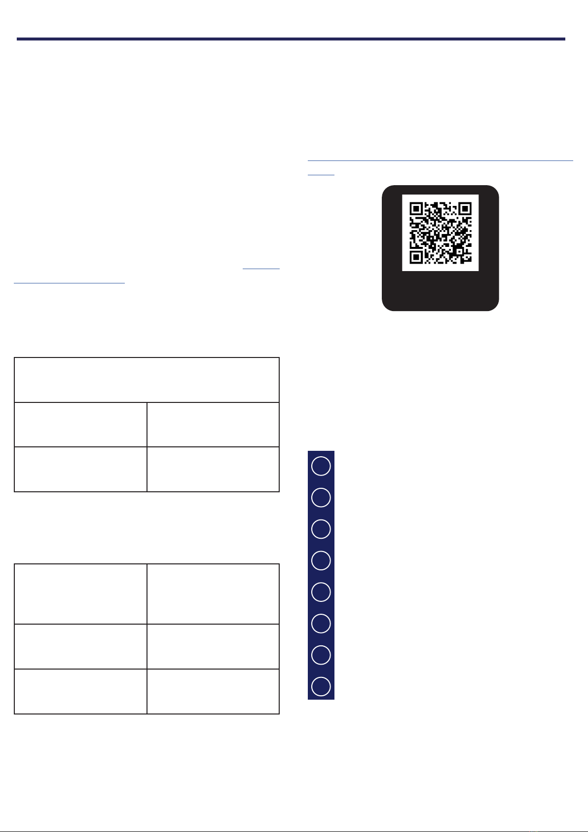
basic setup, as summarized below:
Scan me for direct
Owner Manual access
Explore the next pages of this Quick Guide to go
through each steps of the configuration of your ISP.
BEFORE STARTING
3
4
1
2
5
6
7
8

6
1
2 3 456
9 10 12 13 14 15 16
11
7
8
17
18
1. Standby button
2. Exit button
3. Enter button
4. Edit button
5. Display
6. Volume/Mute knob
7. HDMI In & Out
8. AC Inlet
9. Ethernet port
10. USB ports
11. IR Input/Output
12. Trigger outputs
13. Digital Inputs, Optical
and Coaxial
14. Unbalanced Analog
Inputs
15. Balanced Analog
Input
16. Downmixed Output
17. Channels 1 to 16 Ba-
lanced Outputs
18. Available slots for
optional modules
extending the I/O
capabilities of the ISP
MK2. Refer to Owner
Manual for more
details.
1
21 3
6
45
1. Connect your AC cable to a grounded outlet.
2. Connect your RJ45 LAN cable to your router.
3. Connect your digital sources either via the Toslink
Optical or Coaxial interfaces.
4. Connect your analog stereo sources to the Un-
balanced RCA inputs (for 7.1/5.1 Ch source, refer to
Owner Manual) or Balanced XLR input.
5. Connect the Balanced Outputs 1 to 16 to your am-
plifiers.
6. Connect your HDMI sources on any input from
1 to 7, all supporting HDMI2.0/HDCP2.2, 18 Gbps
speeds.
7. Connect your screen or projector on Outputs 1
and 2, both supporting HDMI2.0/HDCP2.2. Note
that ARC/eARC is only supported in Output 1.
Note: check Owner Manual for other connections.
17
1 - PANELS OVERVIEW
2 - INPUTS AND OUTPUTS CONNECTION

7
System informations:
eth IP Addr :
eth MAC Addr :
Hostname :
serial number :
fw version:
temperature :
FAN speed :
192.168.1.172
b8:27:eb:70:2b:2c
isp_cu
ISP/N200200001
4.0r0
35°C
50%
1. Turn the Main Switch to ON (I) in the back panel.
2. Display will show the logo StormAudio for few se-
conds and will enter Sleep Mode.
3. When in Sleep Mode, press the Power Button. Unit
will start. Wait until the LED is stable green.
4. Press the EDIT button for 4s.
5. System informations will be shown, take note of
the IP address of the unit. Note that your router
must be in DHCP to allow the ISP to get an address
allocated.
12
35
4
6. Open your Web Browser in your laptop and enter
the IP address in the URL area.
Press and hold EDIT to reset the network conguration
The Home page will be shown, select Expert Setup.
You will be prompted for password, use : installer.
6
First time access
Web User Interface description
1
23
Following Expert Setup selection and password va-
lidation, you will reach the first tab of the Web User
Interface (WebUI) called System. On top of each page
of the WebUI, there will be persistent access to:
1. Some key remote control commands of the unit,
such as Source or Preset selection.
2. The Volume control and its related features, inclu-
ding MUTE and DIM (20dB decrease by default).
3. The configuration tabs with each dedicated
to a specific part of the product configuration
amongst them: System, Inputs, Speakers, Settings
and Presets. It also provide Remote Control and
Monitoring page access.
Select the «Inputs» tab to proceed with the Inputs
Configuration.
1 2 3 4 5 6
1. Unused inputs should be turned to N (No) to not
appear in the Remote Control.
2. Default names are given to the inputs. You can
use it unchanged or edit it to your preference.
3. Select which HDMI video input must be activated
when the input is selected.
4. Select where the audio should come from for the
defined input.
5. Select where the audio should come from for the
defined input when selected as Zone2 input in the
Remote Control.
6. Choose to force a Preferred Upmix mode when
selecting the Input.
Note: check Owner Manual for the other settings.
3 - WEB USER INTERFACE ACCESS
4 - INPUTS CONFIGURATION
8
1
234
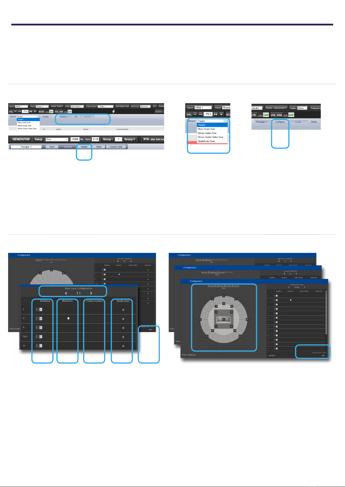
By default a 2 channels theater is defined. If it doesn’t
meet your need, delete it and create a new theater
following below steps:
1. Select Edit Theater 1.
2. When edited, select the Delete button. This will
remove definitely this Theater from the system.
3. You now can create a new Theater corresponding
to your room and speakers setup by selecting
Theater in the drop-down list and then Create.
4. Once created, you need to Configure it.
Note: you can define Theaters and additional Audio
Zones (2ch or mono). We will only cover Theaters confi-
guration in this Guide. Please consult the Owner Ma-
nual for the other cases.
Create your Theater
Configure your Theater
When in the Theater Configurator, you will be able
to define each layer of the speaker installation: base,
height and top layers.
1. Choose using the left and right arrows which
layout you expect for the layer.
2. For each speaker, you can define whether full
bandwidth or multiway, with up to 4 ways defi-
nable.
3. The Center channel can be turned to Phantom
mode, the signal being played in Left and Right
channels.
4. Top speakers can be defined as Dolby Atmos En-
abled for the case up-firing speakers are used. In
such case, select the base speaker location. Keep
«None» for normal down-firing speakers.
5. For each speaker, you can define whether repli-
cation is required. It is often used for multiple
subwoofers use or multiple rows of surround
speakers.
6. Press Next to reach the next layer and follow
again steps 1 to 6 until all three layers are defined.
7. At the end, a summary of the Speakers Configura-
tion is shown.
8. Save to exit and reach the Speakers edition page.
In this part, we will cover the configuration of the
speakers in the installation following Main Speakers
tab selection. As systems might easily get compli-
cated, the Quick Guide will only focus on a basic use
case where full bandwidth passive speakers are used.
We will not treat the specific multi-ways speakers.
Also, we will consider multiple rows of surround spea-
kers as well as multiple subwoofers.
For the case you need a different configuration, we
invite you to refer to the Owner Manual providing ac-
cess to all possible adjustments of the ISP.
2
1
3 4 5 6
78
5 - THEATER DEFINITION (1/2)
9
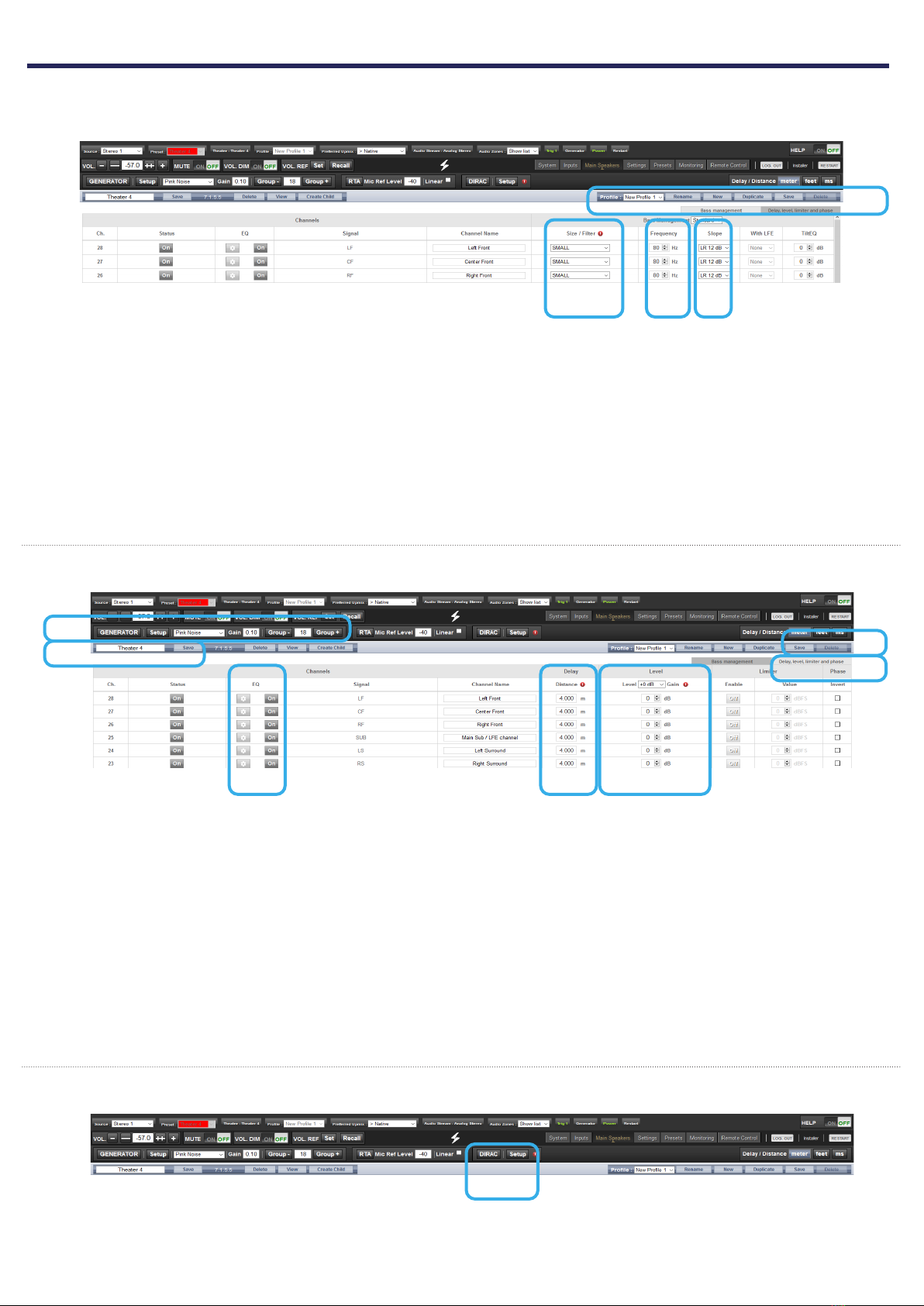
Adjust the Bass Management
Once configured, the Theater is presented in Edition
mode. In this Quick Guide we will only consider the
Standard Bass Management setup:
1. For each Theater, it is possible to define multiple
audio profiles (all Theater settings). By default, a
«New Profile 1» is created.
2. Define the Size of each of your Speaker between
Small, Large and «Large and Sub». Small will fil-
ter the low frequencies and direct them to the
Subwoofer. Large will maintain full bandwidth,
while «Large and Sub» will also direct the Bass to
the subwoofer channel.
3. When in Small, adjust the filter crossover frequen-
cy between speaker and subwoofer.
4. When in Small, adjust the slope between 12dB,
24dB, 36dB and 48 dB/octave (Linkwitz-Riley and
Butterworth types).
1
2 3
Adjust Levels and Delay
1. Select the Delay and Level tab.
2. Set the Distance/Delay of each of the installed
speakers (meter is the default unit, you can select
feet or ms).
Before proceeding to level adjustment, ensure the
Output Mapping matches your connections (see sec-
tion 6).
3. Select the Narrow Band pink noise signal and ac-
tivate the Noise Generator, having first made sure
the Master Volume is not at a too high level, such
as < -30dB. Using the Group +/- button, navigate
through each Speaker. Use the normal Pink Noise
for the Subwoofer adjustment.
4. Adjust the Level for each Speaker using a SPL Me-
ter. We recommend to adjust the Levels with 75
to 85dB(C) average sound pressure as reference.
5. It is possible for each Speaker to adjust up to 20
Parametric EQs. Consult the Owner Manual for
more details.
6. Once adjusted, you can Save your Audio Profile
7. Save the Theater to leave the Edit mode.
6
1
2
3
45
4
Dirac Live Calibration
1
1. Although an important feature of the ISP, we will
not cover the Dirac Live Calibration process in this
Quick Guide as not necessary to get a basic setup
working. Please refer to the Owner Manual, shall
you need to run through the Automated Calibra-
tion process of your ISP using Dirac Live.
7
5 - THEATER DEFINITION (2/2)

10
1. When the physical connections are different from
the default proposed mapping defined during
the configuration of section 5, you can access the
Output Mapping feature when in the Main Spea-
kers tab selecting Output Mapping button.
2. Change the channel assignment using the New
Output expected channel.
3. When completed save the changes to exit and go
back to Speakers page.
1
2
3
1
2
3 4 5 6
1. Definition of Presets is required for playback by
linking a Theater and an Audio Profile and make it
accessible in the Remote Controls. To do so, select
the Presets tab.
2. Some Presets have been created by default while
configuring your Theater. You can create more
Presets using the Create button or delete some.
3. You can change the Preset Name.
4. A Preset is visible and accessible in the Remote
Controls only if Active (Y) in the Presets page.
5. Select which Theater should be activated when
the Preset is selected.
6. Choose which Audio Profile for the selected Thea-
ter needs to be playing. This will call up all the re-
lated audio adjustments.
Access the Web User Interface Remote Control (check
section 3, Home Page and select Remote Control) to
control the ISP from your Web Browser.
Use the iPad Control Application available on the
AppStore (StormRemote): https://itunes.apple.com/
us/app/stormremote/id1216593433?mt=8
Scan me for direct
StormRemote access
6 - OUTPUT MAPPING
7 - PRESETS DEFINITION
8 - REMOTE CONTROL

11
DTS® is a registered trademark of DTS, Inc.
Dolby® is a registered trademark of Dolby Laboratories.
Auro-3D® is a registered trademark of Auro Technologies.
All other trademarks are the properties of their respective owners.
Manufactured under license from Dolby Laboratories. Dolby, Dolby Atmos, Dolby Audio and the double-D symbol
are trademarks of Dolby Laboratories.
Manufactured under license from DTS Licensing Limited. DTS, the Symbol, DTS in combination with the Symbol,
DTS:X, and the DTS:X logo are registered trademarks or trademarks of DTS, Inc. in the United States and/or other
countries. © DTS, Inc. All Rights Reserved.
Manufactured under license from Auro Technologies. StormAudio is certified by Auro Technologies to implement
its technology and products. Auro-3D® and the related symbols are registered trademarks of Auro Technologies.
All materials contained in this work are protected by copyright law and may not be reproduced, distributed,
transmitted, displayed, published or broadcast without the prior written permission of Auro Technologies NV or
in case of third party materials, the owner of that content. You may not alter or remove any trademark, copyright
or other notice from copies of the content.
The terms HDMI and HDMI High-Definition Multimedia Interface, and the HDMI logo are trademarks or registered
trademarks of HDMI Licensing LLC in the United States and other countries.
ACKNOWLEDGEMENTS

StormAudio | Immersive Audio Technologies
15 rue Olympe de Gouges | 44800 Saint-Herblain | France
11-13-2020
Version 2.0
Other manuals for ISP MK2
1
This manual suits for next models
4
Table of contents
Other Storm Audio Recording Equipment manuals


