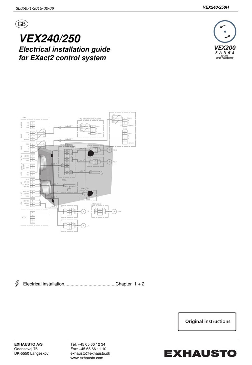
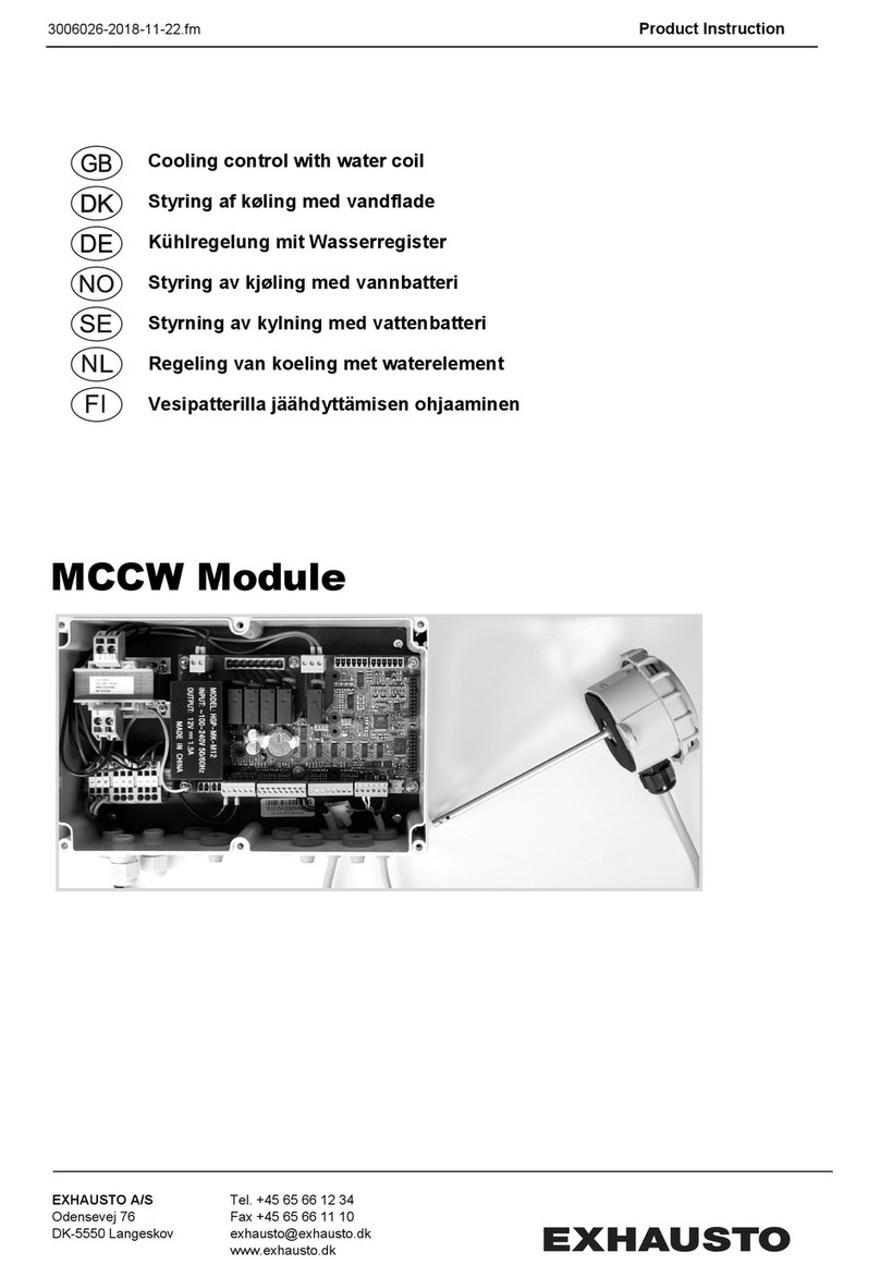
Exhausto EBC 10-P Installation instructions

3916044 09.06 Installation & Operating Manual
USA
CAN
EBC 10 Fan Control
EXHAUSTO Inc.
1200 Northmeadow Pkwy.
Suite 180
Roswell, GA 30076
P: 770.587.3238
F: 770.587.4731
T: 800.255.2923
us.exhausto.com
Job Name:
Installer:
Installation Date:
Product Information
Mechanical Installation
Electrical Installation
Start Up and Conguration
Maintenance and Troubleshooting
.......................... Chapter 1+2
......................... Chapter 3
............................. Chapter 4
.................. Chapter 5
...... Chapter 6
READ AND SAVE THESE INSTRUCTIONS!

2
3916044 09.06
How to use this manual
This installation manual does not contain any system design
documentation. System design documentation is available from any
authorized EXHAUSTO representative.
Accessories, fans and variable frequency drives are not covered by
this manual. Please refer to these component’s individual manuals.
1. Product Information
1.1 Function ...............................................................................................3
1.2 Shipping ...............................................................................................3
1.3 Warranty...............................................................................................3
2. Specications
2.1 Dimensions & Capacities......................................................................4
3. Mechanical Installation
3.1 Location................................................................................................5
3.2 Mounting of Control Unit ......................................................................5
3.3 Connection of the Proven Draft Switch.................................................6
3.4 Installation of the Stack Probe..............................................................6
3.5 Adjusting the Fan Speed ......................................................................7
4. Electrical Installation
4.1 General ................................................................................................8
4.2 Wiring of Heating Appliance.................................................................9
4.3 Wiring of Gas Fireplace .....................................................................10
4.4 Wiring of 3-Phase Fans ...................................................................... 11
4.5 Wiring with a Variable Frequency Drive..............................................12
4.6 Connection of an External Proven Draft Switch .................................13
5. StartupandConguration
5.1 General ..............................................................................................14
5.2 Sequence of Operation ......................................................................14
5.3 Setting the Operating Pressure..........................................................14
6. MaintenanceandTroubleshooting
...........................................................................................................15
!
!
TO REDUCE THE RISK OF FIRE, ELECTRICAL SHOCK OR INJURY TO PERSONS,
OBSERVE THE FOLLOWING:
Caution: Indicates an imminent hazardous situation
which, if not avoided, may result in personal injury or
property damage.
SymbolLegend:
The following terms are used throughout this manual to bring attention
to the presence of potential hazards or to important information
concerning the product.
Danger: Indicates an imminent hazardous situation
which, if not avoided, will result in death, serious injury or
substantial property damage.
1. Use this unit in the manner intended by the manufacturer. If
you have questions, contact the manufacturer at the address or
telephone number listed on the front of the manual.
2. Before servicing or cleaning the unit, switch off at service panel
and lock service panel to prevent power from being switched on
accidentally.
3. Installationworkandelectricalwiringmustbedonebyaqualied
person(s) in accordance with applicable codes and standards.
4. Follow the appliance manufacturer’s guidelines and safety
standards such as those published by the National Fire Protection
Association (NFPA), and the American Society for Heating,
Refrigeration and Air Conditioning Engineers (ASHRAE), and the
local code authorities.
5. This unit must be grounded.

3
3916044 09.06
1. Product Information
1.1 Function
Use The EXHAUSTO EBC 10-P or 10-E Fan Control is for use with single heating appliances where modulation
is not required. It is designed to monitor and create proper draft and pressure in a chimney system. The
control may be used with EXHAUSTO fan models RS, RSV, GSV, RSIB and RSIF.
Typicalusesincludecontrollingdraftforagas-redwaterheater,boiler,furnace,replace,stove,BBQor
pizza oven.
Function The EBC 10-P integrates a fan speed control and an internal Proven Draft Switch (PDS) with a pressure
probe. The EBC 10-E integrates a fan speed control only. This model must be connected to an external
EXHAUSTO PDS-1 to provide the same functions as the EBC 10-P.
The user can set the control to run the exhaust fan continuously. When used with a 3-phase exhaust fan a
Variable Frequency Drive (VFD) is required. It will allow the user to manually adjust the speed of the
fan while it is in use.
The control can also be interlocked with the appliance to make the pre-purge and post-purge functions
available. The pre-purge function prevents the operation of a heating appliance until the set draft point has
been reached. The post-purge function allows the fan to operate for 12 minutes after the appliance
hasbeenshutdown.Thisallowsanyexcessuegasesorproductsofcombustiontoevacuate
the chimney system.
When the EBC 10 is connected to an internal or external PDS, the control provides a safety function that
prevents an appliance from operating in the event of an electrical or mechanical failure. The PDS is
suppliedwithapressureprobethatconstantlysensesthedraftinthechimney.Ifinsufcientdraftexists,
thecontrolwillgraduallyincreasethefanspeeduntilthedraft-setpointissatised.Ifthispointisnot
satisedafter12seconds,thecontrolwillshutdowntheappliance.Thereisanautomaticresetonthe
control to prevent nuissance lockouts or the need for manual reset.
Construction The housing is made of NEMA 1 rated polycarbonate.
Code Compliance System installation must conform to the requirements of the authority having jurisdiction. When required by
the authority having jurisdiction, the installation must also conform to the NFPA31, NFPA54 or NFPA211.
All electrical wiring must be in accordance with the requirements of the authority having jurisdiction or, in
absence of such requirements, with the National Electric Code, NFPA 70.
Listings The circuit board and other components in the EXHAUSTO EBC 10 are ETL or UL listed.
1.2Shipping
EBC 10-P
EBC 10 Control Unit with internal PDS stack pressure probe and silicone tubing
EBC 10-E
EBC 10 Control Unit without PDS
Optional: External PDS, stack pressure probe and silicone tubing.
* If other components are shipped, they will appear as separate items on the packing list.
1.3 Warranty
Complete warranty conditions are available from EXHAUSTO, Inc.

4
3916044 09.06
2.Specications
2.1 Dimensions & Capacities
EBC 10 Control
Power supply V 1x120VAC
Amperage A 6.3
Operating temperature °F/°C -4 to 122/-20 to 50
Control signal mA max. 10
Control relay Max. 120 VAC/8A
Output VAC 10-120
VDC 0-10
Weight lbs/kg 3.0/1.5
EBC10-P EBC10-E

5
3916044 09.06
3. Mechanical Installation
3.1 Location
The EBC 10 Control Unit must be installed indoors in the vertical position, preferably in the room where the
appliance is located. As shown in the diagram below, the control will be wired directly to a 120/1/60 VAC power
supply. The control will also be wired into the appliance and the junction box provided with the fan. For detailed
wiring information, see Chapter 4.
3.2MountingtheControlUnit
The EBC 10 control may be mounted directly to a wall. To mount, remove the cover and locate the (4) mounting
holes. Using the hole-pattern shown below, mount the control using the appropriate sized hardware. Once it
is attached, the unit may be wired in accordance with Chapter 4 and the cover may be replaced.
DISCONNECT
SWITCH
(by others)
JUNCTION BOX
1/4" SILICONE
TUBING
POWER SUPPLY
120/1/60
APPLIANCE CONTROL
INTERLOCK WIRING
10-120V
PROBE
EBC 10
CONTROL
FAN
APPLIANCE
EXHAUSTO
EBC 10
(4) MOUNTING
HOLES
1/4" SILICONE
TUBING
PROBE
EXHAUSTO
EXHAUSTO
EBC 10-EEBC 10-P
Fig.1 Fig.2
Fig.3

6
3916044 09.06
3.3 Connection of the Proven Draft Switch
A Proven Draft Switch (PDS) must be used with the EBC 10 control as a system safety device. The PDS
monitorsthepressureinsidethestackandsignalsthecontroltoshutdowntheapplianceifinsufcientdraft
exists. A stack probe senses the pressure read by the PDS and is connected via silicone tubing.
For model EBC 10-P, connect the silicone tubing through the port located at the bottom of the control
enclosure as shown in Fig. 4 (this port is connected to the internal PDS). The other end should be attached
to the stack probe.
For model EBC 10-E, an external PDS-1 must be wired to terminals 16, 17 and 18 of the control. The
silicone tubing will run from the PDS-1 to the pressure probe. For wiring detail, see Chapter 4.
The standard tube length is 6 feet. The distance can be extended up to 25 feet by using 1/4” rigid plastic or
copper tubing as temperature allows (not supplied).
3.4 Installation of the Stack Probe
The probe must be installed between the appliance and the exhaust fan.
Locatetheprobeatleastadistancethree(3)ventdiametersawayfromanyelbowortee.Forreplace
installations, the stack probe should be installed as close to the exhaust fan as possible. If the probe is
installed on a horizontal pipe, it must be installed above the centerline of the pipe. See Fig. 5.
To produce an accurate pressure reading, theprobeshouldbeinstalledasclosetoushaspossiblewith
theinnerwallofthestack.Ifdoublewalledstackisused,theprobeshouldbeushwiththeinnermostwall.
Ø
Ø
Connection for
tubing at the bottom of
the enclosure
Fig.4
Fig.5

7
3916044 09.06
3.5AdjustingtheFanSpeed
A potentiometer is located on the main control board of the EBC 10. This is used to manually increase or
decrease the speed of the fan. To increase the fan speed, rotate the potentiometer clockwise. Alternately,
rotating the potentiometer counterclockwise will decrease the fan speed.
Potentiometer
Fig.6

8
3916044 09.06
4. Electrical Installation
4.1 General
Danger:Turnoffelectricalpowerbeforeservicing.Contactwithliveelectriccomponentscan
cause shock or death.
EBC10isdesignedfor1x120VACpowersupplyonly.
The designations for each terminal on the control board are shown below. Note that some installations may not
require the use of all terminals. Also shown in this section is a general connection diagram for an EBC 10
control system.
Terminal Use Terminal Use
1 Power Supply - L1 16 PDS- Common
2 Power Supply - N 17 PDS- Normally Closed
3 Power Supply - Ground 18 PDS- Normally Open
4-5 Voltage Input from Appliance Thermostat 19 Chimney Fan- L1
Optocoupler (-) (10-120 VAC/CDC)
6-7 Voltage Input from Appliance Thermostat 20 Chimney/Exhaust Fan- N
Optocoupler (+) (10-120 VAC/CDC) (regulating)
8 24 VDC power supply to dry set of 21 Chimney/Exhaust Fan- Ground
contacts (appliance thermostat)
9 0 VDC power supply to dry set of 25 Control Signal for VFD (0 VDC)
contacts (appliance thermostat)
14 Burner Relay Contact- Common 26 Control Signal for VFD (0 to 10 VDC)
(MAX. 120 VAC, 8 amps)
15 Burner Relay Contact- Normally Open
(MAX. 120 VAC, 8 amps)
!
Fig.7

9
3916044 09.06
4.2WiringofHeatingAppliance
Thegurebelowshowstheconnectionofthecontroldirectlyintothegasvalvefeedingtheappliance.Inthe
eventofanelectrical/mechanicalfailureorinsufcientdraft,thecontrolshutsoffthegassupplycausingthe
appliance to shut down.
The EBC 10-P may also be wired directly to the appliance control (see Fig. 11). If necessary, the control shuts
the appliance down by opening the safety circuit.
NOTE:
EBC 10-E DOES NOT INCLUDE A PDS.
EXTERNALPDS-1ISREQUIRED
Fig.8

10
3916044 09.06
4.3WiringofGasFireplace
WhenconnectingtheEBC10toagasreplace,terminals5and9shouldbeconnectedtoawallswitch.
When the switch is closed, the system is activated. Once proper draft is
achieved,thecontrolreleasesthegas-valveandallowfuelow.Whentheswitchisturnedoff,thecontrol
cutsoffthefuelowandthereplace.Intheeventofinsufcientdraftormechanical/electricalfailure,the
proven draft switch and control will shut off the gas valve.
* Shielded Cable
Fig.9

11
3916044 09.06
4.4Wiringof3-PhaseFans
The EBC 10 can be wired to a 3-phase fan system by incorporating a Variable Frequency Drive.
Fig. 10 shows the connection diagram of this scenario. Wiring detail for this type of system is shown in Fig. 11.
EXHAUSTO
Fig.10

12
3916044 09.06
4.5WiringwithaVariableFrequencyDrive
The EBC 10 Control can be installed with a Variable Frequency Drive (VFD). This allows the fan speed to
be manually adjusted by the user depending on draft conditions. When using a VFD, the fan is NOT
connected directly to the control. The VFD is connected to terminals 25 and 26. The wires running from
the fan junction box is connected into the VFD via terminals W, V and U as shown in the Fig. 11.
Fig.11

13
3916044 09.06
4.6ConnectionofanExternalProvenDraftSwitch
For the EBC 10-E, an external PDS-1 must be installed. The wiring of this is shown in Fig. 12.
A PDS-1 must be used in any of the applications mentioned previously.
# Wires: 3 x 24 AWG (4 x 0.6 mm)
Max. Length: 300’ (100m)
Max. Voltage: 24 V DC <0.1 Amps.
USE SHIELDED CABLE
Fig.12

14
3916044 09.06
5.StartupandConguration
5.1 General
Dip switches are located on the control board. Verify settings using the table below.
5.2SequenceofOperation
1. The appliance energizes EBC 10 inputs at terminals 5 and 6 to initiate the call for heat.
2. The EBC 10 control sets fan output to 100%.
3. The Proven Draft Switch closes when adequate draft is achieved and EBC 10 slows fan to set speed.
4. The EBC 10 control releases the appliance for operation by closing dry contact between terminals 14 and 15.
1. The control adjusts fan output to the percentage set by the control board Potentiometer.
2. If the Proven Draft Switch opens, fan output is set to 100% and a 12 sec. timing cycle starts.
3. If the Proven Draft Switch has not been made within 12 sec., the appliance output turns off and an alarm
condition exists.
4. If the Proven Draft Switch closes, the control automatically resumes normal operation at step 3 of start sequence.
1. The call for heat signal from the appliance is turned off.
2. Fan output continues at pre-set speed for 12 minutes if post purge cycle is selected at dip switch.
3. Fan output is set to zero
5.3SettingtheOperatingPressure
The operating pressure of the EBC 10 Control should be set by the user prior to using the system. This pressure
shouldbesetwithintherangetheappliancemanufacturerhasspeciedintheappliancemanual.Theusermust
use a manometer or other device to read the pressure inside the stack.
Fordrafthoodsordivertersandreplaces,astandardsmoke/ametestshouldbeperformedbeforenormal
operation(speciedinappliancemanual).
Start
Sequence
Operating
Sequence
Shutdown
Sequence
DIP SWITCH NAME OFF ON
1
MANUAL
RESET
Automatic reset
at power failure or
insufcientdraft
Manual reset at
power failure or
insufcientdraft
2
POST
PURGE
No post-purge
12 minutes of post-
purge
3
PDS
CHECK
No monitoring to see
if the PDS was in NC
position prior to start
The PDS must be
in NC position prior
to start
NOTE: The dip switches
will always be OFF if no
Proven Draft Switch is
connected.

15
3916044 09.06
Observation Problem Solution
Heatingappliance/
replacecycleonand
off
- Fan speed
control is set
too low.
- Fan speed
control is bad
- Increase fan speed setting
- Replace fan speed control.
Fanis‘hunting’
(increasingspeedand
thendecreasingspeed
constantly)
- Fan speed
control is set
too low.
- Proven draft
switch setting is
too high
- Increase fan speed setting.
- Lower the pressure setting on the proven draft switch
- Move Stack Probe closer to fan.
Heatingappliance/
replacewillnotcome
on
- Fan is not
working
- No power to
the EBC 10
- Proven
draft switch is
not properly
connected to
the chimney.
- Relay or
proven draft
switch is bad
- Check the fan and if necessary, repair or replace. Check wiring, it may not be receiving
start command.
- Connect power to EBC 10
-Makesuretheprobeisproperlyinsertedintothestack,sothetipoftheprobeisush
withtheinsideofthechimney.Ifservingareplacetheprobeshouldbe3to4belowthe
fan.
- Replace relay or switch
Heatingappliance/
replacewillnotshut
off
- Proven draft
switch is not
wired correct
- EBC 10 is not
wired correctly
- Relay or
proven draft
switch is bad
- Check wiring and correct.
- Check wiring and correct.
- Replace relay
6.MaintenanceandTroubleshooting

EXHAUSTO Inc.
1200 Northmeadow Pkwy.
Suite 180
Roswell, GA 30076
P: 770.587.3238
F: 770.587.4731
T: 800.255.2923
us.exhausto.com
3916044 09.06
Other manuals for EBC 10-P
1
This manual suits for next models
1
Table of contents
Other Exhausto Control Unit manuals
