HIMA HIMax X-SB 01 User manual

X-SB 01
HIMax®
System Bus Module
Manual

HI 801 007 E Rev. 4.00 (1117)
All HIMA products mentioned in this manual are protected by the HIMA trade-mark. Unless noted
otherwise, this also applies to other manufacturers and their respective products referred to herein.
All of the instructions and technical specifications in this manual have been written with great care and
effective quality assurance measures have been implemented to ensure their validity. For questions,
please contact HIMA directly. HIMA appreciates any suggestion on which information should be
included in the manual.
Equipment subject to change without notice. HIMA also reserves the right to modify the written material
without prior notice.
For further information, refer to the CD-ROM and our website http://www.hima.de and
http://www.hima.com.
© Copyright 2011, HIMA Paul Hildebrandt GmbH + Co KG
All rights reserved
Contact
HIMA Address
HIMA Paul Hildebrandt GmbH + Co KG
P.O. Box 1261
68777 Brühl, Germany
Phone: +49 6202 709-0
Fax: +49 6202 709-107
Type of Change
Revision
index
Revisions
technical editorial
4.00 New edition for SILworX V4 X X

X-SB 01 Table of Contents
HI 801 007 E Rev. 4.00 Page 3 of 38
Table of Contents
1Introduction ............................................................ 5
1.1 Structure and Use of this Manual......................................................................... 5
1.2 Target Audience..................................................................................................... 5
1.3 Formatting Conventions ....................................................................................... 6
1.3.1 Safety Notes ............................................................................................................ 6
1.3.2 Operating Tips ......................................................................................................... 7
2Safety...................................................................... 8
2.1 Intended Use .......................................................................................................... 8
2.1.1 Environmental Requirements................................................................................... 8
2.1.2 ESD Protective Measures........................................................................................ 8
2.2 Residual Risk ......................................................................................................... 9
2.3 Safety Precautions................................................................................................. 9
2.4 Emergency Information......................................................................................... 9
3Product Description .............................................. 10
3.1 Safety Function.................................................................................................... 10
3.1.1 Reaction in the Event of a Fault............................................................................. 10
3.2 Scope of Delivery................................................................................................. 10
3.3 Type Label ............................................................................................................ 11
3.4 Structure............................................................................................................... 12
3.4.1 Block Diagram........................................................................................................ 12
3.4.2 Safety-Related Processor System ......................................................................... 12
3.4.3 Interfaces ............................................................................................................... 13
3.4.4 Indicators ............................................................................................................... 14
3.4.5 Module Status Indicators ....................................................................................... 15
3.4.6 Redundancy Indicators .......................................................................................... 16
3.4.7 Rack Connection Indicators................................................................................... 16
3.4.8 Slot Indicators ........................................................................................................ 17
3.4.9 Diagnostic Indicators.............................................................................................. 17
3.4.10 Ethernet Indicators................................................................................................. 17
3.5 Product Data......................................................................................................... 18
3.6 Connector Boards................................................................................................ 19
3.6.1 Pin Assignment...................................................................................................... 19
4Start-up................................................................. 21
4.1 Mounting............................................................................................................... 21
4.2 Mounting and Removing the Module................................................................. 22
4.2.1 Mounting and Removing the Module ..................................................................... 22
4.3 Configuring the Module in SILworX................................................................... 24
4.3.1 Tab: Module........................................................................................................... 24
4.3.2 Tab: Routings......................................................................................................... 26
4.4 Managing the Modules ........................................................................................ 26

Table of Contents X-SB 01
Page 4 of 38 HI 801 007 E Rev. 4.00
5Operation .............................................................. 27
5.1 Handling................................................................................................................27
5.2 Diagnosis ..............................................................................................................27
6Maintenance.......................................................... 28
6.1 Maintenance Measures........................................................................................28
6.1.1 Loading the Operating System...............................................................................28
6.1.2 Proof Test...............................................................................................................28
7Decommissioning.................................................. 29
8Transport .............................................................. 30
9Disposal................................................................ 31
Appendix............................................................... 33
Glossary................................................................................................................33
Index of Figures....................................................................................................34
Index of Tables .....................................................................................................35
Index......................................................................................................................36
X-SB 01 1 Introduction
HI 801 007 E Rev. 4.00 Page 5 of 38
1 Introduction
The present manual describes the technical characteristics of the module and its use. It
provides information on how to install, start up and configure the module in SILworX.
1.1 Structure and Use of this Manual
The content of this manual is part of the hardware description of the HIMax programmable
electronic system.
This manual is organized in the following main chapters:
Introduction
Safety
Product Description
Start-up
Operation
Maintenance
Decommissioning
Transport
Disposal
Additionally, the following documents must be taken into account:
Name Content Document no.
HIMax
System manual
Hardware description of the
HIMax system
HI 801 001 E
HIMax
Safety manual
Safety functions of the HIMax
system
HI 801 003 E
HIMax
Communication manual
Description of communication
and protocols
HI 801 101 E
SILworX Online Help
(OLH)
Instructions on how to use
SILworX
-
First Steps Introduction to SILworX HI 801 103 E
Table 1: Additional Relevant Manuals
The latest manuals can be downloaded from the HIMA website at www.hima.com. The
revision index on the footer can be used to compare the current version of existing manuals
with the Internet edition.
1.2 Target Audience
This document addresses system planners, configuration engineers, programmers of
automation devices and personnel authorized to implement, operate and maintain the
devices and systems. Specialized knowledge of safety-related automation systems is
required.

1 Introduction X-SB 01
Page 6 of 38 HI 801 007 E Rev. 4.00
1.3 Formatting Conventions
To ensure improved readability and comprehensibility, the following fonts are used in this
document:
Bold: To highlight important parts
Names of buttons, menu functions and tabs that can be clicked and
used in SILworX.
Italics: System parameter and variables
Courier Literal user inputs
RUN Operating state are designated by capitals
Chapter 1.2.3 Cross references are hyperlinks even though they are not
particularly marked. When the cursor hovers over a hyperlink, it
changes its shape. Click the hyperlink to jump to the corresponding
position.
Safety notes and operating tips are particularly marked.
1.3.1 Safety Notes
The safety notes are represented as described below.
These notes must absolutely be observed to reduce the risk to a minimum. The content is
structured as follows:
Signal word: danger, warning, caution, notice
Type and source of danger
Consequences arising from the danger
Danger prevention
The signal words have the following meanings:
Danger indicates hazardous situation which, if not avoided, will result in death or serious
injury.
Warning indicates hazardous situation which, if not avoided, could result in death or
serious injury.
Warning indicates hazardous situation which, if not avoided, could result in minor or
modest injury.
Notice indicates a hazardous situation which, if not avoided, could result in property
damage.
NOTICE
Type and source of damage!
Damage prevention
SIGNAL WORD
Type and source of danger!
Consequences arising from the danger
Danger prevention

X-SB 01 1 Introduction
HI 801 007 E Rev. 4.00 Page 7 of 38
1.3.2 Operating Tips
Additional information is structured as presented in the following example:
iThe text corresponding to the additional information is located here.
Useful tips and tricks appear as follows:
TIP The tip text is located here.

2 Safety X-SB 01
Page 8 of 38 HI 801 007 E Rev. 4.00
2 Safety
All safety information, notes and instructions specified in this manual must be strictly
observed. The product may only be used if all guidelines and safety instructions are
adhered to.
This product is operated in accordance with SELV or PELV. No imminent danger results
from the module itself. The use in Ex-Zone is permitted if additional measures are taken.
2.1 Intended Use
HIMax components are designed for assembling safety-related controller systems.
When using the components in the HIMax system, comply with the following general
requirements
2.1.1 Environmental Requirements
Requirement type Range of values
Protection class Protection class III in accordance with IEC/EN 61131-2
Ambient temperature 0...+60 °C
Storage temperature -40...+85 °C
Pollution Pollution degree II in accordance with IEC/EN 61131-2
Altitude < 2000 m
Housing Standard: IP20
Supply voltage 24 VDC
Table 2: Environmental Requirements
Exposing the HIMax system to environmental conditions other than those specified in this
manual can cause the HIMax system to malfunction.
2.1.2 ESD Protective Measures
Only personnel with knowledge of ESD protective measures may modify or extend the
system or replace modules.
NOTE
Device damage due to electrostatic discharge!
When performing the work, make sure that the working area is free of static and
wear an ESD wrist strap.
If not used, ensure that the device is protected from electrostatic discharge, e.g.,
by storing it in its packaging.

X-SB 01 2 Safety
HI 801 007 E Rev. 4.00 Page 9 of 38
2.2 Residual Risk
No imminent danger results from a HIMax module itself.
Residual risk may result from:
Faults in the engineering
Faults in the user program
Faults in the wiring
2.3 Safety Precautions
Observe all local safety requirements and use the protective equipment required on site.
2.4 Emergency Information
A HIMax controller is a part of the safety equipment of a system. If the controller fails, the
system adopts the safe state.
In case of emergency, no action that may prevent the HIMax systems from operating safely
is permitted.

3 Product Description X-SB 01
Page 10 of 38 HI 801 007 E Rev. 4.00
3 Product Description
The X-SB 01 system bus module is intended for use in the programmable electronic
systems (PES) HIMax. The module can only be inserted into base plate's slots 1 and 2.
If the base plate only contains one module, the HIMax system operates with only one
system bus (mono operation). If the base plate contains two modules, the HIMax system
operates with two redundant system busses (redundant operation).
HIMA recommends using redundant operation (default) to exploit the HIMax system
availability.
The module has the following functions:
To establish connections between the modules.
To establish connections to other base plates.
Manage the rack ID and SRS of the modules.
Further, the module provides an interface to the programming and debugging tool (PADT).
The module has been certified by the TÜV for safety-related applications up to SIL 3
(IEC 61508, IEC 61511 and IEC 62061), Cat. 4 (EN 954-1) and PL e (EN ISO 13849-1).
Refer to the HIMax Safety Manual (HI 801 003 E) for more information on the standards
used to test and certify the module and the HIMax system.
3.1 Safety Function
The module transfer the data via a safety-related protocol.
3.1.1 Reaction in the Event of a Fault
If a failure occurs on a system bus, the bus connection is ensured via the redundant system
bus, provided that both system busses have been previously configured.
3.2 Scope of Delivery
The module must be installed on a suitable connector board to be able to operate. The
connector boards for the system bus module are integrated into the base plate and are
contained within the scope of delivery, see Chapter 3.6.

X-SB 01 3 Product Description
HI 801 007 E Rev. 4.00 Page 11 of 38
3.3 Type Label
The type label specifies the following important details:
Product name
Mark of conformity
Bar code (2D or 1D code)
Part number (Part-No.)
Hardware revision index (HW Rev.)
Software revision index (SW Rev.)
Operating voltage (Power)
Ex specifications (if applicable)
Production year (Prod-Year:)
Figure 1: Sample Type Label
3 Product Description X-SB 01
Page 12 of 38 HI 801 007 E Rev. 4.00
3.4 Structure
The module consists of:
Safety-related processor system
Service and system bus interfaces
The module is equipped with LEDs to indicate the status, see Chapter 3.4.4.
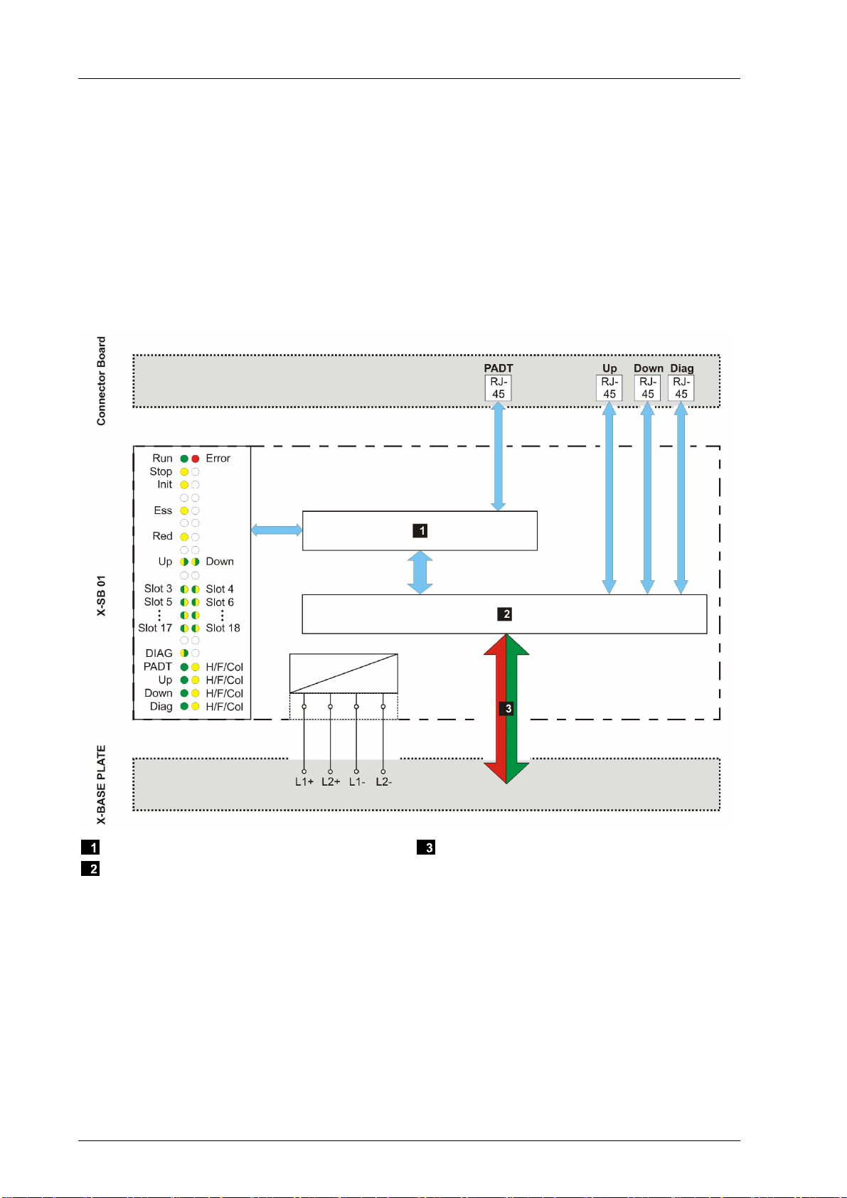
3.4.1 Block Diagram
The following block diagram illustrates the structure of the module.
Safety-Related Processor System
System Bus Controller
System Bus A or System Bus B
Figure 2: Block Diagram
3.4.2 Safety-Related Processor System
The safety-related 1oo2 processor system controls and monitors one system bus of the
HIMax system. The X-SB 01 module in slot 1 controls and monitors the system bus A and
the module in slot 2 controls and monitors the system bus B.
Operating system and error code history are stored in a non-volatile memory which can be
read in SILworX via the diagnosis.
X-SB 01 3 Product Description
HI 801 007 E Rev. 4.00 Page 13 of 38
3.4.3 Interfaces
The connector board associated with the module is equipped with the following interfaces:
One service interface (PADT)
Two system bus interfaces (UP, DOWN)
One diagnostic interface (DIAG), for future applications
Service Interface PADT
The service interface allows the user to connect to the PADT. The service interface can be
used to load both the user program into the processor module and the operating system
into the individual modules.
Service interface PADT
Number 1
Transfer standard 10/100 Base-T, half and full duplex
Auto Negotiation Yes
Auto Crossover No
Connection socket RJ-45
IP Address Freely configurable
Subnet Mask Freely configurable
Table 3: Specifications for the Service Interface
iThe service interface does not support auto crossover. A crossover cable must be used for
point-to-point connections.
System Bus Interface UP, DOWN
The system bus interfaces are used to connect to additional base plates in the HIMax
system and are configured with the SILworX programming tool. To connect the interfaces,
use cables complying with Ethernet megabit standard (at least CAT 5e cable).
System bus interfaces
Number 2
Auto crossover Yes
Connection socket RJ-45
Labeling Up, Down
Table 4: Specifications for the System Bus Interface
Diagnostic Interface DIAG
Diagnostic interface reserved for further applications
3 Product Description X-SB 01
Page 14 of 38 HI 801 007 E Rev. 4.00
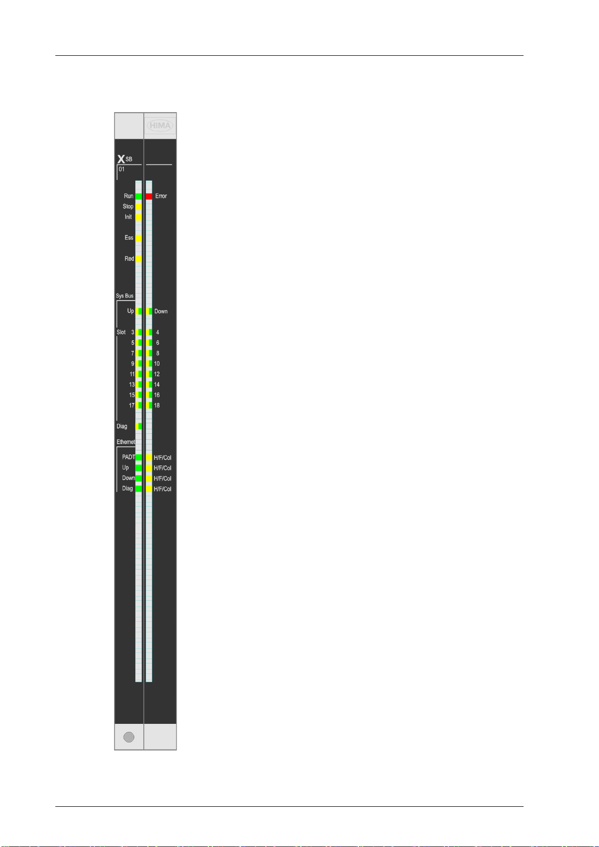
3.4.4 Indicators
The following figure shows the LED indicators for the module.
Figure 3: Indicators

X-SB 01 3 Product Description
HI 801 007 E Rev. 4.00 Page 15 of 38
The LEDs indicate the operating state of the module.
The LEDs on the module are divided into six groups:
Module status indicators (Run, Error, Stop, Init)
Redundancy indicators (Ess, Red)
Rack connection indicators (Up, Down)
Slot indicators (Slot 3…18)
Diagnostic indicators (Diag)
Communication indicators (Ethernet)
When the supply voltage is switched on, a LED test is performed and all LEDs briefly flash
simultaneously.
Definition of Blinking Frequencies
The following table defines the blinking frequencies of the LEDs:
Name Blinking Frequencies
Blinking1 Long (approx. 600 ms) on, long (approx. 600 ms) off
Blinking2 Short (approx. 200 ms) on, short (approx. 200 ms) off, short (approx. 200
ms) on, long (approx. 600 ms) off
Blinking-x Ethernet communication: Flashing in sync with data transfer
Table 5: Blinking Frequencies of LEDs
3.4.5 Module Status Indicators
These LEDs are located on the front plate, on the upper part of the module.
LED Color Status Description
On Module in RUN, normal operation
Blinking1 Module state:
STOP/OS_DOWNLOAD or
OPERATE (only with processor modules)
Run Green
Off Module not in RUN,
observe the other status LEDs
On/Blinking1 Internal module faults detected by self-tests, e.g.,
hardware, software or voltage supply.
Fault while loading the operating system
Error Red
Off Normal operation
On Module state:
STOP / VALID CONFIGURATION
Blinking1 Module state:
STOP / INVALID CONFIGURATION or
STOP / OS_DOWNLOAD
Stop Yellow
Off Module not in STOP, observe the other status LEDs
On Module state: INIT, observe the other status LEDs
Blinking1 Module state: LOCKED, observe to the other status
LEDs
Init Yellow
Off Module state: neither INIT nor LOCKED, observe
the other status LEDs
Table 6: Module Status Indicators

3 Product Description X-SB 01
Page 16 of 38 HI 801 007 E Rev. 4.00
3.4.6 Redundancy Indicators
The LEDs are located below the module status indicators.
LED Color Status Description
On Caution: Removing an operating system bus
module cause the system to fail!
The SB module is
running in mono operation (only 1 system bus active)
configured in SILworX
The module is absolutely required for operating the
HIMax system!
Blinking1 Caution: Removing an operating system bus
module cause the system to fail!
The SB module is inserted and configured for redundant
operation, but the redundant module is not available.
The module is absolutely required for operating the
HIMax system!
Ess Yellow
Off The system bus module is not absolutely required for
operation! Observe the Red LED!
On Redundant operation, the SB module is operating
redundantly.
The redundant SB module periodically allocates
identical system/rack IDs
(the adjustment of the system/rack IDs was successful).
Blinking1 Redundancy setting
Red Yellow
Off No redundant operation!
Table 7: Redundancy Indicators
3.4.7 Rack Connection Indicators
The rack connection and slot LEDs are labeled Sys Bus.
LED Color Status Description
On Physical and logical connection to the system bus module
in another base plate.
Green
Blinking1 Transient disturbances on the system bus
On The modules recognizes additional system bus modules
on the system bus
Yellow
Blinking1 Only a physical connection to the system bus module in
another base plate.
Up
Off Off No connection to another system bus module.
On Physical and logical connection to the system bus module
in another base plate.
Green
Blinking1 Transient disturbances on the system bus
On The modules recognizes additional system bus modules
on the system bus
Yellow
Blinking1 Only a physical connection to the system bus module in
another base plate.
Down
Off Off No connection to another system bus module.
Table 8: Rack Connection Indicators

X-SB 01 3 Product Description
HI 801 007 E Rev. 4.00 Page 17 of 38
3.4.8 Slot Indicators
The slot indicator LEDs are located after the Slot label.
LED Color Status Description
Green On Module inserted in slot X, logical connection established.
Yellow Blinking1
Module inserted in slot X, logical connection not
established.
3...18
Off Off Slot X not used
Table 9: Slot Indicators
3.4.9 Diagnostic Indicators
Diagnostic indicators reserved for future applications!
3.4.10 Ethernet Indicators
The communication LEDs are labeled Ethernet.
LED Color Status Description
Blinking-x Communication detected on interface.
Blinking1 IP address conflict detected.
LEDs adjacent to one another,
PADT and H/F/Col blinking
PADT Green
Off PADT not connected.
On Speed = 100 Mbit/s
Blinking-x not defined!
Blinking1 IP address conflict detected.
LEDs adjacent to one another,
PADT and H/F/Col blinking
H/F/Col
(PADT)
Yellow
Off Speed = 10 Mbit/s or no connection.
On System bus module connected, physical connection
established.
Up Green
Off No system bus module connected.
On System bus module connected, physical connection
established.
Down Green
Off No system bus module connected.
On Diagnostic device connected, physical connection
established
Diag Green
Off No diagnostic device connected.
On Full duplex operation on the F line
Blinking-x Collision detected on the Col line
H/F/Col
(Up,
Down,
Diag)
Yellow
Off Half duplex operation on Hline
Table 10: Communication Indicators

3 Product Description X-SB 01
Page 18 of 38 HI 801 007 E Rev. 4.00
3.5 Product Data
General
Supply voltage 24 VDC, -15 %...+20 %, rP≤5 %,
SELV, PELV
Current input max. 0.65 A
Operating temperature 0…+60 °C
Storage temperature -40…+85 °C
Humidity max. 95 % relative humidity, non-condensing
Type of protection IP20
Dimensions (H x W x D) 310 x 29.2 x 230 mm
Weight approx. 1.2 kg
Table 11: Product Data
Figure 4: Views

X-SB 01 3 Product Description
HI 801 007 E Rev. 4.00 Page 19 of 38
3.6 Connector Boards
The connector boards connect the system modules to the Ethernet interfaces. Two
connector boards are secured to the base plate: one left connector board (L) for slot 1 and
one right connector board (R) for slot 2. The connector boards contain information on the
number of modules (10, 15 or 18) that can be inserted into the base plate and the
corresponding slot IDs.
Slot Left/Right Slot ID
1 Left (L) 62
2 Right (R) 63
Table 12: Connector Boards
3.6.1 Pin Assignment
The interface name is printed on the connector boards.
Figure 5: Connector Boards

3 Product Description X-SB 01
Page 20 of 38 HI 801 007 E Rev. 4.00
Designation Description
External interface
PADT (X1) Connection for the PADT
External system bus interfaces
UP (X2) Connection for additional HIMax base plates
DOWN (X3) Connection for additional HIMax base plates
External diagnostic interface
DIAG (X4) Connection reserved for future applications
Table 13: Description of the Connector Boards
Table of contents
Other HIMA Control Unit manuals

HIMA
HIMA HIMax X-DI 32 51 User manual

HIMA
HIMA HIMax X-CI 24 01 User manual

HIMA
HIMA HIMatrix F60 Installation and operation manual

HIMA
HIMA HIMatrix F60 DI 32 01 User manual

HIMA
HIMA HIMax X-DI 32 05 User manual

HIMA
HIMA HIMax X-MIO 7 01 User manual

HIMA
HIMA DIO 24/16 01 User manual

HIMA
HIMA HIMax X-DO 12 51 User manual

HIMA
HIMA HIMax X-DI 64 01 User manual

HIMA
HIMA HIMax X-HART 32 01 User manual


