manuals.online logo
Brands
  1. Home
  2. •
  3. Brands
  4. •
  5. Leviton
  6. •
  7. Control Unit
  8. •
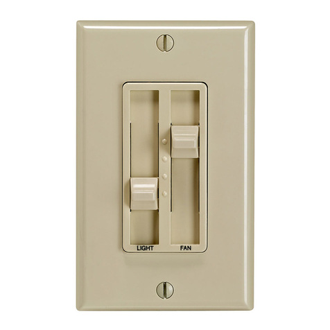
  9. Leviton Decora Illumatech RTF01-10 User manual

Leviton Decora Illumatech RTF01-10 User manual

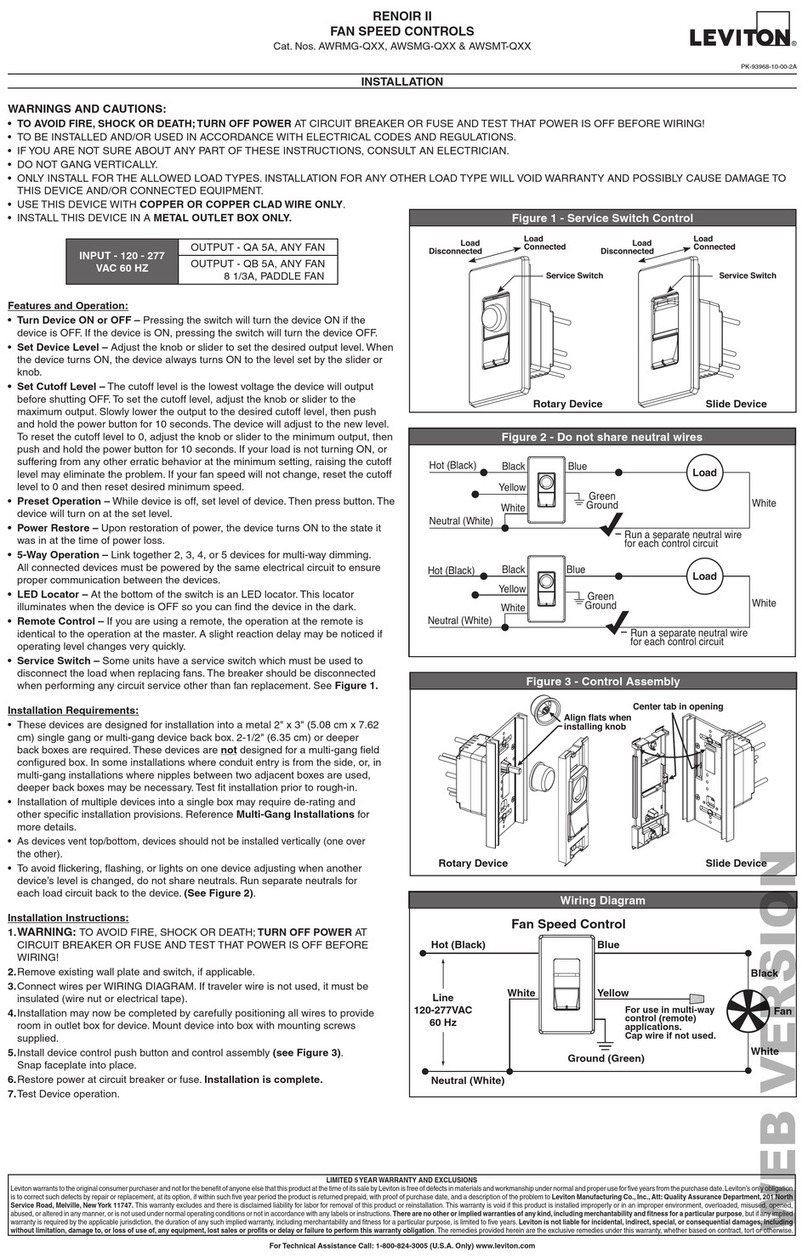
Quiet Fan Speed Control - Single Pole (One location)
Fan Speed Control
Cat. No. RTF
Ø
1-1
Ø
Rated: 1.5A-120VAC, 60Hz
INSTALLATION INSTRUCTIONS
WARNINGS AND CAUTIONS:
• Tobeinstalledand/orusedinaccordancewithappropriateelectricalcodesandregulations.
• Ifyouareunsureaboutanypartoftheseinstructions,consultaqualiedelectrician.
• Toavoidoverheatingandpossibledamagetothisdeviceandotherequipment,donotinstallto
controlareceptacle,uorescentlighting,amotor-oratransformer-operatedapplianceotherthan
appropriateceilingfans.
• Toreducetheriskofreorelectricalshock,thiscontrolistobeusedwithceilingfansthatarerated
120VAC,totalload1.5amperesmaximum.
WARNINGS AND CAUTIONS:
• Foruseonceilingpaddlefanswithsplit-capacitororshadedpolemotorsonly.Pleasereferto
manufacture’sinstructionsorratinglabelonthemotortoconrmtype.Usewithanyothertypesof
motorsorequipmentmaycauseoverheatingand/ordamagetothemotorsorequipment.
• Disconnectpoweratcircuitbreakerorfusewhenservicingxture.
• Usethisdeviceonlywithcopperorcoppercladwire.Withaluminumwireuseonlydevicesmarked
CO/ALRorCU/AL.
Slotted/PhillipsScrewdriver ElectricalTape
Pliers Pencil
Cutters Ruler
Ifacolorchangekitisprovidedwithyourdevice,proceedwiththe
followingstepifyouneedtochangethecolor.Otherwise,proceedwith
the“Installing Fan Speed Control by itself or with other devices”
section.
NOTE:ThereisNOderatingnecessaryformulti-ganginstallationsof
thisFanSpeedControl.
Anynumberoffansofthesametypemaybecontrolledbyasinglefan
speedcontrolprovidedthatthetotalamperageofthefansdonot
exceedtheamperageofthefanspeedcontrol.
NOTE:Usecheckboxes √whenStepsarecompleted.
WARNING: Toavoidre,shock,ordeath;TURN OFF
POWERatcircuitbreakerorfuseandtestthatpowerisoff
beforewiring!
Removing existing switch: Removeexisting
wallplateandswitchmountingscrews.Carefullypullswitch
fromwallbox.DO NOTremovewiresattachedtotheswitch
atthistime.
Identifying your wiring application (most
common):
NOTE:Ifthewiringinthewallboxdoesnotresemblethis
singlepoleconguration,consultaqualiedelectrician.
YourFanSpeedControlincludestwocoloroptions.TheControlshipswith
theWhiteframeattached.Tochangecolorofframe,proceedasfollows:
IfinstallingControlinasingledeviceapplication,proceedwiththe
MULTI-FAN CONTROLsection.IfinstallingControlinamulti-device
application,proceedasfollows:
CHANGING THE COLOR OF YOUR FAN SPEED
CONTROL
MULTI-DEVICE APPLICATION
MULTI-FAN CONTROL
INSTALLING YOUR FAN SPEED CONTROL
Tools needed to install your Fan Speed Control:
Color Change Option:
Step 1
Step 2
Step 3
Installing Fan Speed Control by itself or with other
devices
ONOFF
ONOFF
ONOFF
ONOFF
ONOFF
ONOFF
ONOFFONOFF
ONOFF
ONOFF
ONOFF
ONOFF
O
F
F
M
A
X
H
I
M
E
D
L
O
O
F
F
M
A
X
H
I
M
E
D
L
O
Push in side at tab
to release. Remove
frame and knob.
Press on knob. Line up
tabs on back of frame and
press in side to attach
Single-Pole:
Lookatthebackofyourswitch.Thereshouldbe2wiresconnectedto
twoscrewterminals(notincludingagreenorbarecopperwireusedfor
grounding),youhaveaSingle-Poleswitch.
Insert wires
straight then twist
clockwise
Electrical
Tape
Strip 5/8"
(1.6 cm)
Cut
(if necessary)
Strip Gage
5/8"
(1.6 cm)
Disconnecting switch wires and preparing wires:
Single-Pole Wiring Application:
• Disconnectwiresfromscrewterminalsor
Quickwire™slots(shown).
• Pulloffpre-cutinsulationfromControl
leads.
• Makesurethattheendsofthewiresfrom
thewallboxarestraight (cut if
necessary).
• Remove5/8”(1.6cm)ofinsulationfrom
eachwireinthewallbox(shown).
Press in slot and
pull out wire
Step 4
Step 5
Black
Red
Neutral
Green
Ground
DI-000-RTF01-02C
Single-Pole Wiring Application:
• Restorepoweratcircuit
breakerorfuse.
• Carefullyholdingcontrolas
shown,rotateknobtotheMAX
position.FanshouldturnON
tohighestlevel.Rotateknobto
theremaininglevels:HI,MED,
andLO.Fanspeedshould
changeaccordingly.
If fan does not turn ON, refer
to the TROUBLESHOOTING
section.
• FandoesnotturnONordoesnotrunMulti-speed
 -Circuitbreakerorfusehastripped.
 -FanNeutralconnectionisnotwired.
 -Fanhasburnedout.
For non-standard wiring applications, refer
to Wire Nut and Conductor Size Chart
Connect wires per WIRING DIAGRAM as follows:
Screwwirenutsonclockwisemakingsurenobare
conductorsshowbelowthewireconnectors.Secureeach
connectorwithelectricaltape.
• GreencontrolGroundleadtoGreenorbarecopper
wireinwallbox.
• BlackcontrolleadtoLine(Hot)wallboxwireremoved
fromoldswitch.
• Redcontrolleadtoremainingwallboxwire.
•Proceed to Step 6.
Testing your Fan Speed Control prior to
mounting in wall box:
Fan Speed Control Mounting:
TURN OFF POWER AT CIRCUIT BREAKER OR FUSE.
Restore Power: Restorepoweratcircuitbreakeror
fuse. Installation is complete.
Step 6
Step 7
OPERATION
TROUBLESHOOTING
Step 8
Step 9
Installationmaynowbecompleted
bycarefullypositioning
allwirestoprovideroominwallbox
forcontrol.Mountcontrol
intoboxwithmountingscrews
supplied.Attachwallplate.
ON
Rotatebottomcontrolknobtooneofthe
fourlevels:MAX,HI,MED,andLO
–Fanwillincreaseordecreaseinspeed
respectivelyfordesiredlevel.
OFF
Rotatebottomcontrolknobfullycounter-
clockwisetotheOFFposition–Fanwill
turnOFF.
WIRE NUT / # OF CONDUCTOR
COMBINATION CHART
 1-#12w/1to3#14,#16or#18
 2-#12w/1or2#16or#18
 1-#14w/1to4#16or#18
 2-#14w/1to3#16or#18
Step 5
con’t
O
F
F
M
A
X
H
I
M
E
D
L
O
O
F
F
M
A
X
H
I
M
E
D
L
O
O
F
F
M
A
X
H
I
M
E
D
L
O
Hot (Black)
Neutral (White)
Fan
Fan Speed
Black
Green
Ground
Black
White
Red
Line
120VAC, 60Hz
O
F
F
M
A
X
H
I
M
E
D
L
O
PRODUCT INFORMATION
• Fortechnicalassistance,contactusat1-800-824-3005.
• Visitourwebsiteatwww.leviton.com.
LIMITED 5 YEAR WARRANTY AND EXCLUSIONS
LevitonwarrantstotheoriginalconsumerpurchaserandnotforthebenetofanyoneelsethatthisproductatthetimeofitssalebyLevitonisfreeofdefectsinmaterialsandworkmanshipundernormalandproperuseforveyearsfromthepurchasedate.Leviton’sonlyobligation
istocorrectsuchdefectsbyrepairorreplacement,atitsoption,ifwithinsuchveyearperiodtheproductisreturnedprepaid,withproofofpurchasedate,andadescriptionoftheproblemtoLeviton Manufacturing Co., Inc., Att: Quality Assurance Department, 59-25 Little
Neck Parkway, Little Neck, New York11362-2591.Thiswarrantyexcludesandthereisdisclaimedliabilityforlaborforremovalofthisproductorreinstallation.Thiswarrantyisvoidifthisproductisinstalledimproperlyorinanimproperenvironment,overloaded,misused,opened,
abused,oralteredinanymanner,orisnotusedundernormaloperatingconditionsornotinaccordancewithanylabelsorinstructions.Therearenootherorimpliedwarrantiesofanykind,includingmerchantabilityandtnessforaparticularpurpose,butifanyimpliedwarrantyis
requiredbytheapplicablejurisdiction,thedurationofanysuchimpliedwarranty,includingmerchantabilityandtnessforaparticularpurpose,islimitedtoveyears.Levitonisnotliableforincidental,indirect,special,orconsequentialdamages,includingwithoutlimitation,damage
to,orlossofuseof,anyequipment,lostsalesorprotsordelayorfailuretoperformthiswarrantyobligation.Theremediesprovidedhereinaretheexclusiveremediesunderthiswarranty,whetherbasedoncontract,tortorotherwise.
DI-000-RTF01-02C
2008©LevitonMfg.Co.,Inc.

Other Leviton Control Unit manuals

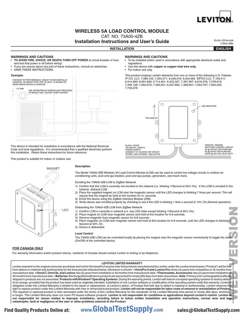
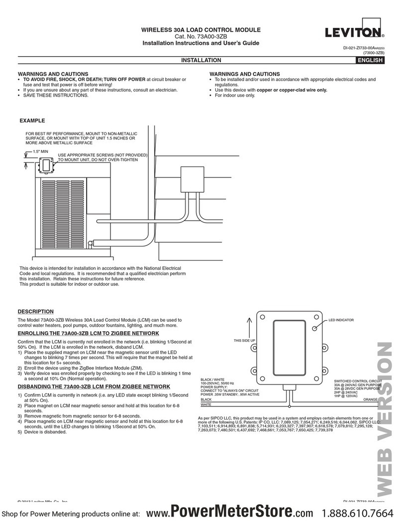
Leviton 73A00-3ZB Mounting instructions

Leviton

Leviton 73A00-3ZB Mounting instructions

Leviton decora 6630 User manual

Leviton

Leviton decora 6630 User manual

Leviton CP series Operation manual

Leviton

Leviton CP series Operation manual

Leviton SureSlide 6637 User manual

Leviton

Leviton SureSlide 6637 User manual

Leviton 73A00-4ZB Mounting instructions

Leviton

Leviton 73A00-4ZB Mounting instructions

Leviton VRCS4-1L Vizia RF + User manual

Leviton

Leviton VRCS4-1L Vizia RF + User manual

Leviton miniZ Series User manual

Leviton

Leviton miniZ Series User manual

Leviton 95A03-1 Mounting instructions

Leviton

Leviton 95A03-1 Mounting instructions

Leviton 59A00-1 User manual

Leviton

Leviton 59A00-1 User manual

Leviton LV200 User manual

Leviton

Leviton LV200 User manual

Leviton SPLCH User manual

Leviton

Leviton SPLCH User manual

Leviton SGAMP User manual

Leviton

Leviton SGAMP User manual

Leviton 47603-ASO User manual

Leviton

Leviton 47603-ASO User manual

Leviton rMB81-001 Operation manual

Leviton

Leviton rMB81-001 Operation manual

Leviton 73A00-4ZB Mounting instructions

Leviton

Leviton 73A00-4ZB Mounting instructions

Leviton Verifeye 8000 Series User manual

Leviton

Leviton Verifeye 8000 Series User manual

Leviton UPB Mounting instructions

Leviton

Leviton UPB Mounting instructions

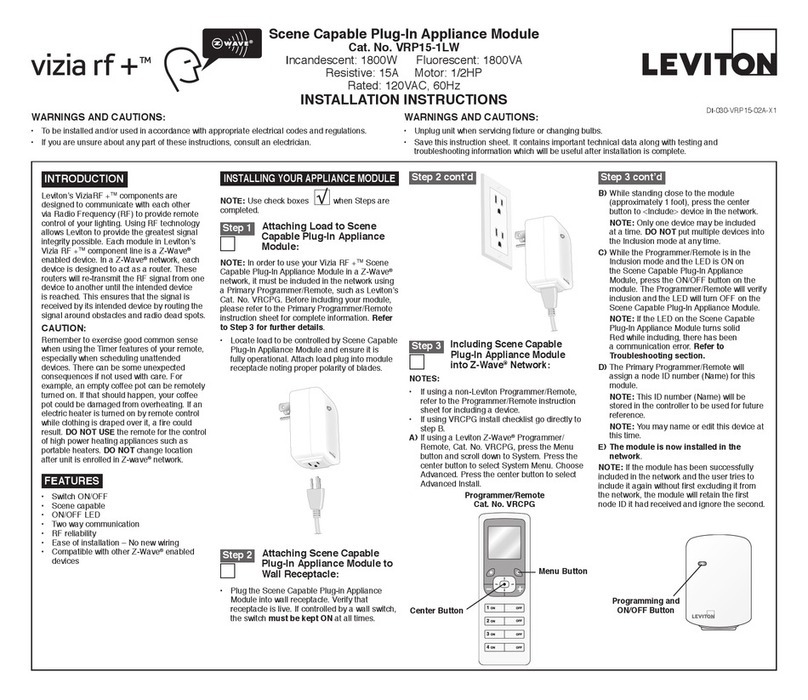
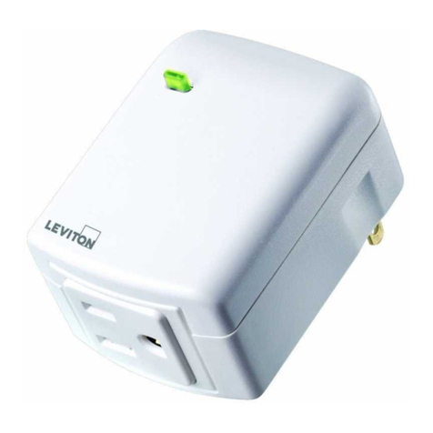
Leviton Vizia RF+ VRP15-1LW User manual

Leviton

Leviton Vizia RF+ VRP15-1LW User manual

Leviton 73A00-3ZB Mounting instructions
Leviton

Leviton 73A00-3ZB Mounting instructions

Leviton 476TL-T12 User manual

Leviton

Leviton 476TL-T12 User manual

Leviton N7516 Original operating instructions

Leviton

Leviton N7516 Original operating instructions

Leviton 73A00-3ZB Mounting instructions

Leviton

Leviton 73A00-3ZB Mounting instructions

Leviton MC 7516 User manual

Leviton

Leviton MC 7516 User manual

Leviton 71I00-1 Mounting instructions

Leviton

Leviton 71I00-1 Mounting instructions

Popular Control Unit manuals by other brands

CFH 52113 manual

CFH

CFH 52113 manual

WAGO 761-113 manual

WAGO

WAGO 761-113 manual

Leroy-Somer R 725A Connection and Adjustments

Leroy-Somer

Leroy-Somer R 725A Connection and Adjustments

CIRCUIT DESIGN CDP-RX-07MP Operation guide

CIRCUIT DESIGN

CIRCUIT DESIGN CDP-RX-07MP Operation guide

GEA VARIVENT DN 25 Operating	 instruction

GEA

GEA VARIVENT DN 25 Operating instruction

IBA ibaClock manual

IBA

IBA ibaClock manual

AMCI SD17060E2 user manual

AMCI

AMCI SD17060E2 user manual

Texas Instruments TCA7408EVM user guide

Texas Instruments

Texas Instruments TCA7408EVM user guide

Dover PSG BLACKMER AIR VALVE Installation, operation and maintenance instructions

Dover

Dover PSG BLACKMER AIR VALVE Installation, operation and maintenance instructions

Zimmer DDOC00734 manual

Zimmer

Zimmer DDOC00734 manual

IDTECK UOM user manual

IDTECK

IDTECK UOM user manual

TA Hydronics STAF-SG Series manual

TA Hydronics

TA Hydronics STAF-SG Series manual

Burkert 265X instruction manual

Burkert

Burkert 265X instruction manual

PDi PD295-001 Installation and operating instructions

PDi

PDi PD295-001 Installation and operating instructions

GSD WXT26M2101B quick start guide

GSD

GSD WXT26M2101B quick start guide

LinMot DM01-23 Series installation guide

LinMot

LinMot DM01-23 Series installation guide

Eurolube 53430 manual

Eurolube

Eurolube 53430 manual

Enterasys VH-STACK Quick installation guide

Enterasys

Enterasys VH-STACK Quick installation guide

manuals.online logo
manuals.online logoBrands
  • About & Mission
  • Contact us
  • Privacy Policy
  • Terms and Conditions

Copyright 2025 Manuals.Online. All Rights Reserved.