Exhausto VEX300 Series User manual

Electrical installation guide
VEX310T-320T-330T-340T-350T
For third-party control systems
RD14102-01
Electrical installation........................................ Chapter 2 + 3
Original instructions
3006011-2020-10-20 VEX300T-X
EXHAUSTO A/S
Odensevej 76
DK-5550 Langeskov
Tel. +45 65 66 12 34
Fax: +45 65 66 11 10
www.exhausto.dk

Symbols, concepts and warnings
Symbols, terms and warnings.............................................................................. 3
1. Power supply diagram
1.1. Connection diagrams for VEX with motor control (MC).....................................4
1.1.1. Diagram VEX310T........................................................................................... 4
1.1.2. Diagram VEX320T-350T..................................................................................6
1.1.3. The alarm relay function VEX320T-350T.........................................................8
2. Installation of the VEX unit
2.1. Scope of installation..............................................................................................9
2.2. Dimensioning and installation..............................................................................9
2.2.1. Electrical connection/data ............................................................................. 10
2.3. Electrical components.........................................................................................10
2.3.1. Control system panel..................................................................................... 10
3006011-2020-10-20
2/12

Symbols, concepts and warnings
Symbols, terms and warnings
Prohibition symbol Failure to observe instructions marked with a prohibition symbol
may result in serious or fatal injury.
Danger symbol Failure to observe instructions marked with a danger symbol
may result in personal injury and/or damage to the unit.
Scope of the in-
struction manual
This instruction manual is for use with EXHAUSTO AHUs, hereafter named as the
VEX unit. This instruction manual deals with the electrical installation. Please refer
to the product instructions regarding accessories and extra equipment.
The instructions must be fully observed to ensure personal safety and the safety
of others, and to protect equipment and ensure the correct operation of the VEX
unit. EXHAUSTO A/S accepts no liability for accidents caused by a failure to use
the product in accordance with the manual’s instructions and specifications.
Warning The work must be performed by an authorised electrician, in ac-
cordance with locally applicable regulations and legislation.
Opening the air
handling unit
Do not remove the detachable doors/panels until the supply volt-
age has been disconnected at the isolation switch and the fans
have stopped.
Isolation switch In accordance with The Machinery Directive*, an isolation switch
must be permanently installed in the unit.
The isolation switch must:
● be lockable or positioned in plain sight in the immediate vicinity of the unit
● disconnect all poles from the supply voltage
● be constructed in accordance with EN 60204-1
The isolation switch is not supplied by EXHAUSTO.
Information plate The information plate is positioned to the left of the control system box
The VEX unit information plate shows:
● the VEX variant designation
● unit production order no./year
NB: Always have the production order number ready when contacting EXHAUS-
TO A/S.
3006011-2020-10-20 Symbols, concepts and warnings
3/12
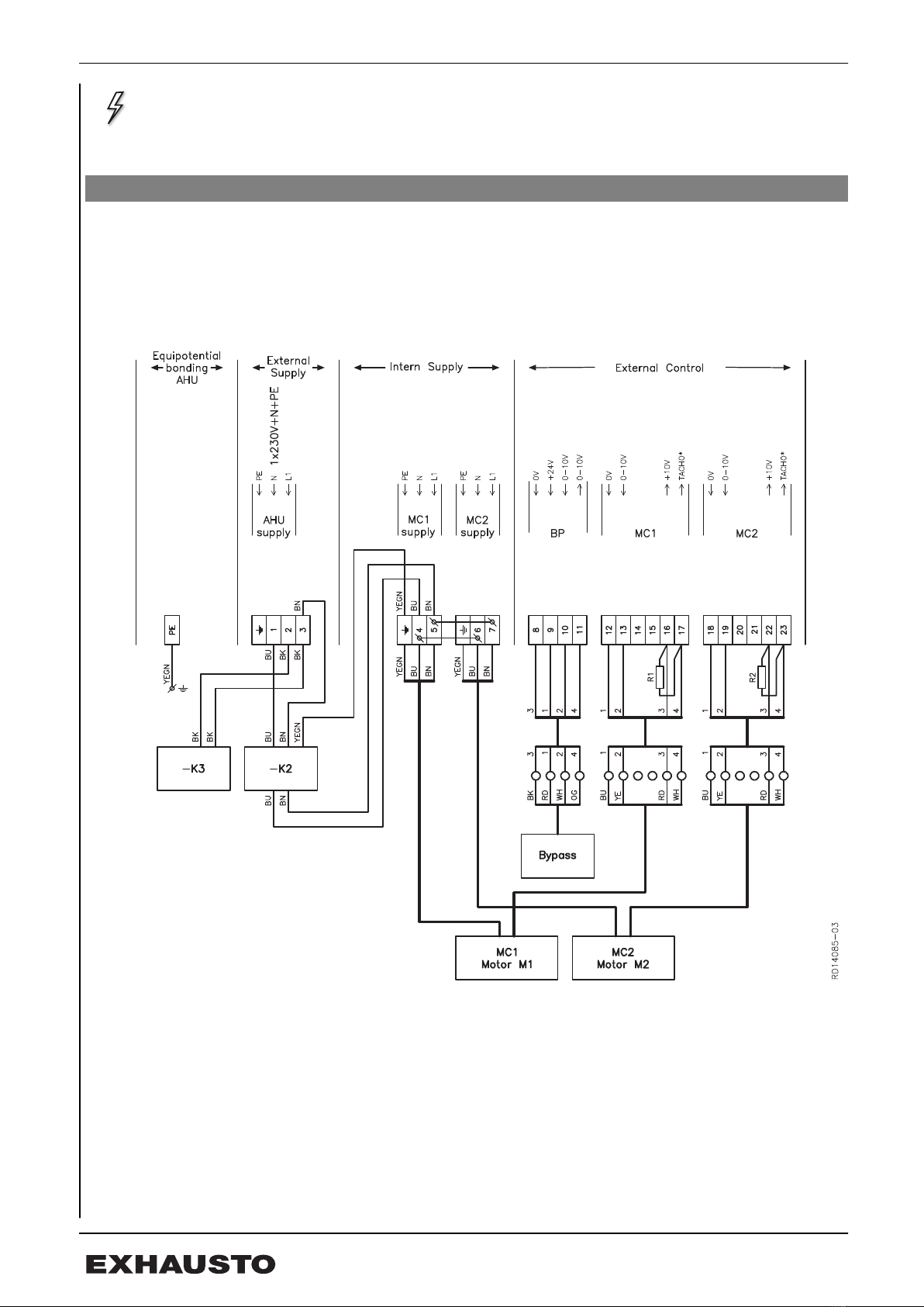
1. Power supply diagram
1.1 Connection diagrams for VEX with motor control (MC)
The diagrams below illustrate connection of the power supply to the motor control,
filters and bypass damper.
1.1.1 Diagram VEX310T
*TACHO [Hz] x 60 = rpm
3006011-2020-10-20 Power supply diagram
4/12

Explanation of dia-
gram designation Explanation
MC1 (Supply) Motor control supply MC1 (exhaust / exhaust air)
MC2 (Supply) Supply for motor control MC2 (supply air / outdoor air)
Bypass Control signal for bypass damper (return / exhaust air)
MC1 (External Con-
trol)
Control signal for motor control motor M1 (exhaust / ex-
haust air)
MC2 (External Con-
trol)
Control signal for motor control motor M2 (supply air / out-
door air)
-K2 EMC filter
-K3 Passive motor filter
-R1 4.7 kΩ resistor for TACHO signal from M1
-R2 4.7 kΩ resistor for TACHO signal from M2
3006011-2020-10-20 Power supply diagram
5/12
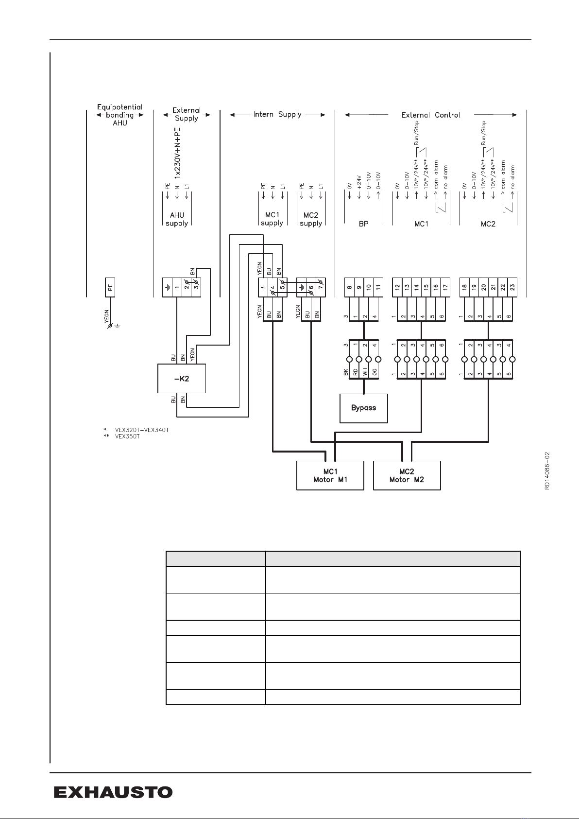
1.1.2 Diagram VEX320T-350T
Key to diagram
Designation Explanation
MC1 (Supply) Power supply for motor control MC1 (exhaust air/extract
air)
MC2 (Supply) Power supply for motor control MC2 (supply air/outdoor
air)
Bypass Control signal for bypass damper (exhaust/extract air)
MC1 (External Con-
trol)
Control signal for motor control M1 (exhaust air/extract
air)
MC2 (External Con-
trol)
Control signal for motor control M2 (supply air/outdoor
air)
-K2 EMC filter
3006011-2020-10-20 Power supply diagram
6/12
Note Other parts, shown on the front page of the VEX instructions, are supplied by EX-
HAUSTO (Assembly and installation)
3006011-2020-10-20 Power supply diagram
7/12

1.1.3 The alarm relay function VEX320T-350T
Description Drawing
Connection
The drawing shows which
two terminals from MC are
connected to the terminal
block -X1 in the control
system panel.
Function
The alarm relay position in
the case of power failure
or similar.
(Power OFF)
The alarm relay position in
case of alarm.
(Alarm)
The alarm relay position
during operation.
(Power ON, no alarm)
3006011-2020-10-20 Power supply diagram
8/12

2. Installation of the VEX unit
2.1 Scope of installation
Control system
panel
Wiring configurations for the terminal block in the control system panel:
● Motor and motor control (MC) supply voltage
● Motor control (MC) signals and Tacho signal/alarm relay
● Bypass damper control signal
NB: ● The fan motors have overload protection and are pre-programmed at the fac-
tory.
● The motor control must have short-circuit protection.
For other technical data, see the “Technical data” section in the VEX instructions.
Assembly and installation.
Bypass damper
function
When connecting the control signal to the bypass damper, the following must be
taken into consideration:
Control voltage
for BP1
Function
≤ 2V 100% heat recovery.
Outdoor air is led through the counterflow heat exchanger.
10 V 0% heat recovery.
The outdoor air bypasses the counterflow heat exchanger
(bypass).
2.2 Dimensioning and installation
● The supply cable must be dimensioned and installed in ac-
cordance with applicable rules and regulations.
● The earth terminal (PE) must always be connected.
Diagram The supply voltage must be connected to the isolation switch as shown in the dia-
gram in section 1.
Fuses The fuses must be suitable for:
● Short-circuit protection of the VEX unit.
● Short-circuit protection of supply cable
● Overload protection of supply cable
3006011-2020-10-20 Installation of the VEX unit
9/12

Maximum fuse rat-
ing VEX size Maximum fuse rating
310T C-10A
320T C-16A
330T C-16A
340T C-16A
350T C-16A
Note For a VEX unit with short-circuit protection, the fuse rating must not be greater rat-
ing than stated in the table above.
2.2.1 Electrical connection/data
The following table shows the dimensioned power consumption and phase current.
VEX size Material
(fan impeller)
Power
supply
(nominal)
MC1/MC2
phase current [A]
Dimensioned
power consumption
(total) [A]
310T composite 1 x 230 V + N + PE
~50/60Hz
1.7/1.7 3.4
320T composite 1 x 230 V + N + PE
~50/60Hz
2.1/2.1 4.2
330T composite 1 x 230 V + N + PE
~50/60Hz
3.7/3.7 7.4
330T aluminium 1 x 230 V + N + PE
~50/60Hz
2.1/2.1 4.2
340T composite/
aluminium
1 x 230 V + N + PE
~50/60Hz 3.5/3.5 7.0
350T composite 1 x 230 V + N + PE
~50/60Hz
5.9/5.9 11.8
350T aluminium 1 x 230 V + N + PE
~50/60Hz
5.7/5.7 11.4
Note Power consumption is not sinusoidal.
2.3 Electrical components
2.3.1 Control system panel
The illustration below shows the electrical components’ positioning in the control sys-
tem panel:
3006011-2020-10-20 Installation of the VEX unit
10/12

RD14090-02
-X1
-K2
-K3
Component list
Code Electrical component PCS.
-X1 Terminal block 2.5 □
3 (yellow / green)
3 (blue)
20 (gray)
-K2 EMC filter 1
-K3 Passive motor filter (only in VEX310T) 1
For positioning of electrical components in the VEX unit, see the VEX instructions.
Assembly and installation.
3006011-2020-10-20 Installation of the VEX unit
11/12
Other manuals for VEX300 Series
12
This manual suits for next models
5
Table of contents
Popular Industrial Equipment manuals by other brands

Piranha
Piranha IRONWORKER P90 Operation manual

Rockwell Automation
Rockwell Automation Allen-Bradley 1606-XLSREDS40HE Reference manual

Spartan Equipment
Spartan Equipment Mini Pick-Up Broom Operator's manual

Thermo Scientific
Thermo Scientific CryoExtra CE8100 Series Operating and maintenance manual

Panasonic
Panasonic EXC24CE quick start guide

Graco
Graco 223627 Instructions-parts list


