HWH 2000 SERIES User manual

H
CORPORATION
H
W
R
FEATURING:
TOUCH PANEL CONTROL
AIR LEVELING (WITH TAG AXLE)
HWH COMPUTER-CONTROLLED
OPERATOR’S MANUAL
DUMP
SECURELY BEFORE REMOVING TIRES OR CRAWLING UNDER VEHICLE.
UNDERSTAND OPERATOR’S MANUAL BEFORE USING. BLOCK FRAME AND TIRES
CAUTION!
NOT IN
TRAVEL
EXCESS
SLOPE
PARK/
BRAKE
ONE OR TWO ROOM EXTENSIONS
(WITH ROOM LOCKS AND AIR SEALS)
RAISE
AIR
HWH COMPUTERIZED LEVELING
2000 SERIES
LEVELING SYSTEM
30MAY01
ML25178/MP05.998E
TRAVEL
EMERGENCY
STOP
(ON I-80, EXIT 267 SOUTH)
INTERNET: http: //www.hwhcorp.com
(800) 321-3494 / (563) 724-3396
MOSCOW, IOWA 52760
2096 MOSCOW ROAD
HWH CORPORATION
MODE
MODE
AP24574

CAUTION !
READ THE ENTIRE OPERATOR’S MANUAL BEFORE OPERATING.
MOVE FORWARD OR BACKWARD WITHOUT WARNING CAUSING INJURY OR DEATH.
CAUSING INJURY OR DEATH.
CHIPS, OIL LEAKS, ETC. FOLLOW ALL OTHER APPLICABLE SHOP SAFETY PRACTICES.
OPERATOR’S MANUAL
MP15.4501
30MAY01
BLOCK FRAME AND TIRES SECURELY BEFORE CRAWLING UNDER VEHICLE. DO NOT USE LEVELING JACKS OR AIR
SUSPENSION TO SUPPORT VEHICLE WHILE UNDER VEHICLE OR CHANGING TIRES. VEHICLE MAY DROP AND/OR
NEVER PLACE HANDS OR OTHER PARTS OF THE BODY NEAR HYDRAULIC LEAKS. OIL MAY PENETRATE SKIN
WEAR SAFETY GLASSES WHEN INSPECTING OR SERVICING THE SYSTEM TO PROTECT EYES FROM DIRT, METAL
IMPORTANT: IF COACH IS EQUIPPED WITH A ROOM EXTENSION, READ ROOM EXTENSION SECTION BEFORE
OPERATING LEVELING SYSTEM.
DO NOT OPERATE THE LEVELING SYSTEM OR USE THE DUMP OR RAISE BUTTONS IF THE VEHICLE IS MOVING
IN EXCESS OF 5 MPH.
KEEP ALL PEOPLE CLEAR OF VEHICLE WHILE LEVELING SYSTEM AND ROOM EXTENSION ARE BEING OPERATED.
HOW TO OBTAIN WARRANTY SERVICE
THIS IS NOT TO BE INTERPRETED AS A STATEMENT OF WARRANTY
HWH CORPORATION strives to maintain the highest level of
customer satisfaction. Therefore, if you discover a defect or
problem, please do the following:
(563) 724-3396 OR (800) 321-3494. Give your name and
coach was purchased, or the date of system installation,
Notify the dealership where you purchased the
vehicle or had the leveling system installed. Dealership
management people are in the best position to resolve
the problem quickly. If the dealer has difficulty solving
the problem, he should immediately contact the Customer
Service Department, at HWH CORPORATION.
If your dealer cannot or will not solve the problem,
notify the Customer Service Department:
HWH CORPORATION 2096 Moscow Rd. Moscow IA. 52760
address, coach manufacturer and model year, date the
SECOND:
FIRST:
authorization of an independent service facility, to be
defective part, either by appointment at the factory or by the
CORPORATION will authorize repair or replacement of the
determine whether or not your claim is valid. If it is, HWH
HWH CORPORATION personnel will contact you to
during business hours (8:00 a.m. till 5:00 p.m. c.s.t.).
description of the problem, and where you can be reached
determined by HWH CORPORATION. All warranty repairs
must be performed by an independent service facility
authorized by HWH CORPORATION, or at the
HWH CORPORATION factory, unless prior written approval
has been obtained from proper HWH CORPORATION
personnel.

CONTROL IDENTIFICATION
"EMERGENCY STOP" BUTTON
"EXCESS SLOPE"
"NOT IN PARK"
RAISE RIGHT SIDE BUTTON
LOWER RIGHT SIDE BUTTON
LEVELING LIGHTS
(4 - Yellow)
WARNING LIGHTS
(4 - Red)
RAISE REAR BUTTON
LOWER REAR BUTTON
"AIR" (ON) BUTTON
DUMP LIGHT
"TRAVEL MODE" BUTTON
"TRAVEL MODE"
This button will lower the whole coach by
dumping air from the suspension system.
This button will raise the whole coach
by adding air to the suspension system.
ON if the leveling system
can NOT level the coach.
CONTROL BUTTONS
MP25.998D
31OCT02
CONTROL FUNCTIONS
LEVELING SYSTEM
"DUMP" BUTTON
RAISE LEFT SIDE
BUTTON
LOWER LEFT SIDE
BUTTON
RAISE FRONT BUTTON
LOWER FRONT BUTTON
Flashes when "RAISE" button is pushed.
"AIR" BUTTON:
"DUMP" BUTTON:
"RAISE" BUTTON:
UP ARROWS (RAISE BUTTONS):
DOWN ARROWS (LOWER BUTTONS):
IMPORTANT:
DUMP LIGHT:
RAISE LIGHT:
"EXCESS SLOPE" LIGHT:
WARNING LIGHTS:
LEVELING LIGHTS:
"NOT IN PARK/BRAKE" LIGHT:
LIGHT
LIGHT
Flashes when "DUMP" button is pushed.
This is the system active and automatic
operation button. It works if the ignition is in the "ON" position.
These momentary
buttons are used for manually operating the air leveling
systems. Sides or ends of the vehicle will lower while these
buttons are pushed.
One or two yellow lights can be on
indicating the side, end or corner of the coach is low.
Function with the ignition in the
"ON" position. ON when the LEVELING SYSTEM ACTIVE
LIGHT is ON. See PREPARATION FOR TRAVEL.
Read "DUMP AND RAISE FUNCTIONS"
before using the "DUMP" or "RAISE" buttons.
CAUTION!
HWH COMPUTERIZED LEVELING
UNDERSTAND OPERATOR’S MANUAL BEFORE USING. BLOCK FRAME AND TIRES
SECURELY BEFORE REMOVING TIRES OR CRAWLING UNDER VEHICLE.
NOT IN
PARK /
BRAKE
DUMP
RAISE
EMERGENCY
STOP
AIR
TRAVEL
TRAVEL
EXCESS
SLOPE
RAISE LIGHT
"RAISE" BUTTON
"EMERGENCY STOP" BUTTON: This button turns the
"RAISE" buttons. Pushing this button will NOT put the system
system OFF but does NOT control power to the "DUMP" or
"TRAVEL MODE" BUTTON:
LEVEL SYSTEM ACTIVE LIGHT: ON when the system is
active, and flashes during automatic leveling.
"TRAVEL MODE" LIGHT (GREEN):
INDICATOR LIGHTS
"TRAVEL MODE" BUTTON LIGHT (RED):
This button will put the Leveling
System in the TRAVEL mode. The ignition must be "ON" for
ON if the ignition is in
the "ON" position, the system is not being used, and there is
sufficient air pressure in the suspension.
"TRAVEL MODE" BUTTON
LIGHT (Red)
Light flashes
for 3 seconds after the "TRAVEL MODE" button is pushed.
the vehicle to return to proper ride height for traveling.
ON while the "AIR" button
is being pushed if the Park Brake is NOT set. The light will go
out when the "AIR" button is released.
HARD RESET SWITCH
(SEE HWH LIGHTED RESET SWITCH)
MASTER WARNING LIGHT
These momentary
buttons are used for manually operating the air leveling
systems. Sides or ends of the vehicle will raise while these
buttons are pushed.
ACTIVE LIGHT
LIGHT (Green)
MODE
MODE
in the TRAVEL mode.
See PREPARATION FOR TRAVEL.
ON any time the
MASTER WARNING LIGHT:
"TRAVEL" light is not ON, if the ignition is in the
"ON" position.

26APR02
MP25.998F
ROOM CONTROL SWITCH:
the room cannot be operated, and the key can be removed.
removed. When the KEY SWITCH is in the "OFF" position
POSITION the room can be operated, and the key cannot be
CONTROL SWITCH. When the KEY SWITCH is in the "ON"
The KEY SWITCH controls power to the ROOMKEY SWITCH: READY TO OPERATE LIGHT:
CONTROL FUNCTIONS
KEY SWITCH
USING. KEEP PEOPLE AND OBSTRUCTIONS
CLEAR OF ROOM WHEN OPERATING. RETRACT
UNDERSTAND OPERATOR’S MANUAL BEFORE
CAUTION!
ON
LIGHT (AMBER)
READY TO OPERATE
ROOM CONTROL
HYDRAULIC ROOM EXTENSION
OFF EXTEND SWITCH
H
HW
CORPORATION
R
ROOM EXTENSION OPERATOR’S PANEL
CONTROL IDENTIFICATION
PUMP ON INDICATOR
LIGHT (RED)
The ROOM CONTROL SWITCH
is a two position momentary switch. Pressing the switch in the
EXTEND POSITION will extend the room. Pressing the switch
in the RETRACT POSITION will retract the room. Releasing
the ROOM CONTROL SWITCH will halt the operation of the
room.
PUMP ON INDICATOR LIGHT: This light will be on when the
pump is running.
This light will flash for 20
seconds while the air seal deflates, after the KEY SWITCH
is turned on. It will then glow steady. Except for EXCESS
SLOPE situations, the room cannot be extended or
If the "EXCESS SLOPE" light on the leveling system
control panel is on, the READY TO OPERATE light will flash
continously after the key switch is turned ON. The room
will not extend. The room will retract if the room control
If the PARK BRAKE is not set, the READY TO OPERATE
light will not turn on and flash when the KEY SWITCH is
turned "ON".
MASTER WARNING LIGHT
This light is on the dash, separate from the control panels.
It can be on only if the ignition key is in the "ON" position. The light will be on if a HWH low air pressure switch is on,
the TRAVEL mode, or if a room in or room lock limit switch
OPERATE light will flash if the KEY SWITCH is in the "ON"
use, MANUAL or AUTOMATIC operation, the READY TO
position. The room will not operate.
If a RAISE or LOWER function of the Leveling System is in
if the Leveling System is on, if the Leveling System is not in
is not made.
switch is pushed to "RETRACT".
NOTE: Any time the KEY SWITCH is ON, the network will
be active and will not power down.
PUMP ON STEADY / READY TO
FLASH / WAIT
OPERATE
retracted if this light is flashing.

MP25.999
5
18MAR2
1
CONTROL IDENTIFICATION
PUMP RUN TIME
SYSTEM VARIATIONS FOR PUMP RUN TIME
Contact HWH corporation to get specific information about the system in this vehicle.
No matter what HWH system is on the vehicle, the pump should not be ran for more than three minutes
(3" motors) or six minutes (3.7" or 4.5" motors) without allowing the pump motor to cool for thirty minutes.
Continuous operation of the pump motor without allowing the motor to cool can damage the pump motor.
Some HWH systems are equipped with a lighted reset switch.
If the processor turns the pump off because the run time has
been exceeded, the light in the reset switch will turn on. The
With some systems, when the processor has turned the pump off because the run time has been exceeded, power
to the HWH system must be turned off and back on before the system will operate. With motorized vehicles, turn the
ignition off and back on. With non-motorized vehicles, turn the master power switch for the HWH system off and back
DO NOT continue without allowing the pump motor to cool for thirty minutes.
When operating some leveling systems manually or operating the room extensions, the pump will turn off and back
on while pushing the control button when the pump run time has been exceeded.
the pump motor to cool for thirty minutes.
Some systems can be turned back on immediately after the processor turns the pump off.
back on or run the pump without allowing the pump motor to cool for thirty minutes.
Some systems with rooms run the rooms separate from the system processor. These systems do not monitor pump
run time when operating the rooms.
pump motor to cool for thirty minutes.
The HWH systems with a computer processor monitor the pump run time and will turn the pump off if the run time exceeds a
specified time. This time can vary with different systems. Due to available electronics or system design, the pump run time
programs will also vary. Leveling systems and room extensions that are not controlled by a system processor have no pump
run time protection.
thirty minutes.
Pump motors used with HWH leveling systems and room extension systems come in 3 different diameters; 3", 3.7" and 4.5".
Contact the vehicle manufacturer or HWH for help with identifying the motor size.
runs for more than three minutes with a 3" motor; or six minutes with a 3.7" or 4.5" motor that the motor is allowed
to cool for thirty minutes before continuing. Continuous operation of the pump motor without allowing the motor
PUMP RUN TIME
It is important that any time the pump
to cool can damage the motor.
DO NOT run the pump more than three or six minutes without allowing the pump motor to cool for
DO NOT run the pump more than three or six minutes without allowing the
DO NOT turn the system
DO NOT continue without allowin
g
on.
system will not operate until the reset switch is pushed.
DO NOT continue without allowing the pump motor to
cool for thirty minutes. LIGHTED RESET SWITCH
For cold weather information see "COLD WEATHER OPERATIONS" below.
COLD WEATHER OPERATIONS
HWH leveling and room extension systems are designed to function in cold weather down to 0 degrees Fahrenheit. Below
freezing (32 degrees Fahrenheit) the jacks or rooms will operate slower than usual.
For operation in temperatures dropping below -20 degrees Fahrenheit, it is necessary that the system is equipped with oil
designed for extreme cold weather application such as a synthetic oil. (Contact HWH for recommendations.)
DO NOT run the pump motor continuously.
Continuous operation of the pump with slow moving jacks or rooms in cold weather, without allowing the pump motor to
cool will cause the pump motor to burn up and damage the pump assembly.
It is important that any time the pump runs for more than three minutes
continuing. Continuous operation of the pump motor without allowing the motor to cool can damage the motor.
with a 3" motor; or six minutes with a 3.7" or 4.5" motor that the motor is allowed to cool for thirty minutes before

OPERATING PROCEDURES
MP35.485C
26APR02
NETWORK INFORMATION
GENERAL INSTRUCTIONS
Maintain adequate clearance in all directions for vehicles,
room extensions, doors, steps, etc.. Vehicle may move in any
direction due to raising or lowering of vehicle during leveling,
settling of vehicle, equipment malfunction, etc..
The MASTER WARNING LIGHT will be on if an air bag has
low pressure or if a room in or room lock limit switch is not
made, if the ignition is in the "ON" position.
CAUTION:
ROOM IS EXTENDED. DO NOT MOVE THE VEHICLE AT
If the Park Brake is not set, the Leveling System cannot
be turned ON and the room extension will not operate.
NEUTRAL HOLD OVERRIDE SWITCH
HWH LIGHTED RESET SWITCH
transmission will not shift out of NEUTRAL, using a key or a
screwdriver turn the HOLD OVERRIDE selector switch to the
If the lighted reset switch is on, the switch must be pushed
before any room or the leveling system can be operated.
A network problem with one room will not inhibit the use of
A network problem with the leveling system will not inhibit
the use of the room extensions after the reset switch is
the other rooms or leveling system after the reset switch is
pushed.
pushed.
If a room is not fully retracted and locked the transmission
will not shift out of "NEUTRAL".
If the rooms are fully retracted and locked and the left in the "110" position for normal operation.
If the operation of the room is halted and the lighted reset
switch is on, there may be a problem with an unlock limit
switch. The room mechanism should be checked and
repaired before trying to operate that room again. Operating
a room with a lock extended may cause extensive damage
If the lighted reset switch will not go out when pushed, there
is a problem with the central control module of the network
system. No rooms or the Leveling System will operate.
The vehicle suspension will return to the travel mode if the
IF THE IGNITION IS IN THE "ON"
POSITION AND THE LIGHTED RESET SWITCH IS ON,
THE VEHICLE CAN RETURN TO RIDE HEIGHT WITHOUT
RELEASING THE PARK BRAKE.
ignition key is in the "ON" position.
to the room.
CAUTION:
possible. The HOLD OVERRIDE selector switch should be
position labeled "220" the switch is located on the outside of
the Central Control Module. This will allow the transmission
to be shifted. The system should be serviced as soon as
If a ROOM CONTROL SWITCH is being pushed, no other
room or the Leveling System can be operated. If any Leveling
System raise or lower function is being operated, no room
control switch will work.SPEEDS IN EXCESS OF 5 MPH IF THE MASTER
WARNING LIGHT IS ON.
Excessive operation of the hydraulic pump can shut the HWH
CAN network down. The lighted reset switch will be on if the
ignition is on. The reset button must be pushed before any
operation can continue. Allow the pump to cool before
continuing hydraulic operations.
The HWH 2000 series CAN system is a computerized
modular network. It controls all functions of the leveling
system and the room extensions. The network is active any
time the ignition is in the "ON" position or when any room
extension control panel key is "ON". Certain functions and
indicator lights for the leveling system will work when the
network is active. Certain functions and lights will work ONLY
if the the ignition is in the "ON" position to start the function.
The "DUMP" and "RAISE" buttons will function with the
leveling system and park brake off, if the ignition is in the
"ON" position or if the network is active. See AIR DUMP
AND RAISE FUNCTIONS section of this manual.
The HWH lighted reset switch is located on the shifter panel.
If there is a failure at any time in the HWH CAN network, the
network will shut down. The leveling system and all room
extensions will not operate. If the ignition is off, no indicator
lights will come on. If the ignition is in the "ON" position, the
lighted reset switch and the MASTER WARNING Light will
come on.
NOTE: The network will stay active for 10 minutes after
the ignition key and all room extension control panel
keys have been turned "OFF". If the leveling system
was turned "ON", the network will stay active for 10
minutes after automatic leveling is complete or the
system goes "EXCESS SLOPE". If manual leveling
buttons were used, the network stays active for 10
minutes after the last manual button is released.
DO NOT MOVE THE VEHICLE IF A

OPERATING PROCEDURES
MP35.485J
26APR02
PREPARATION FOR TRAVEL
Check that all room extensions are fully retracted and locked
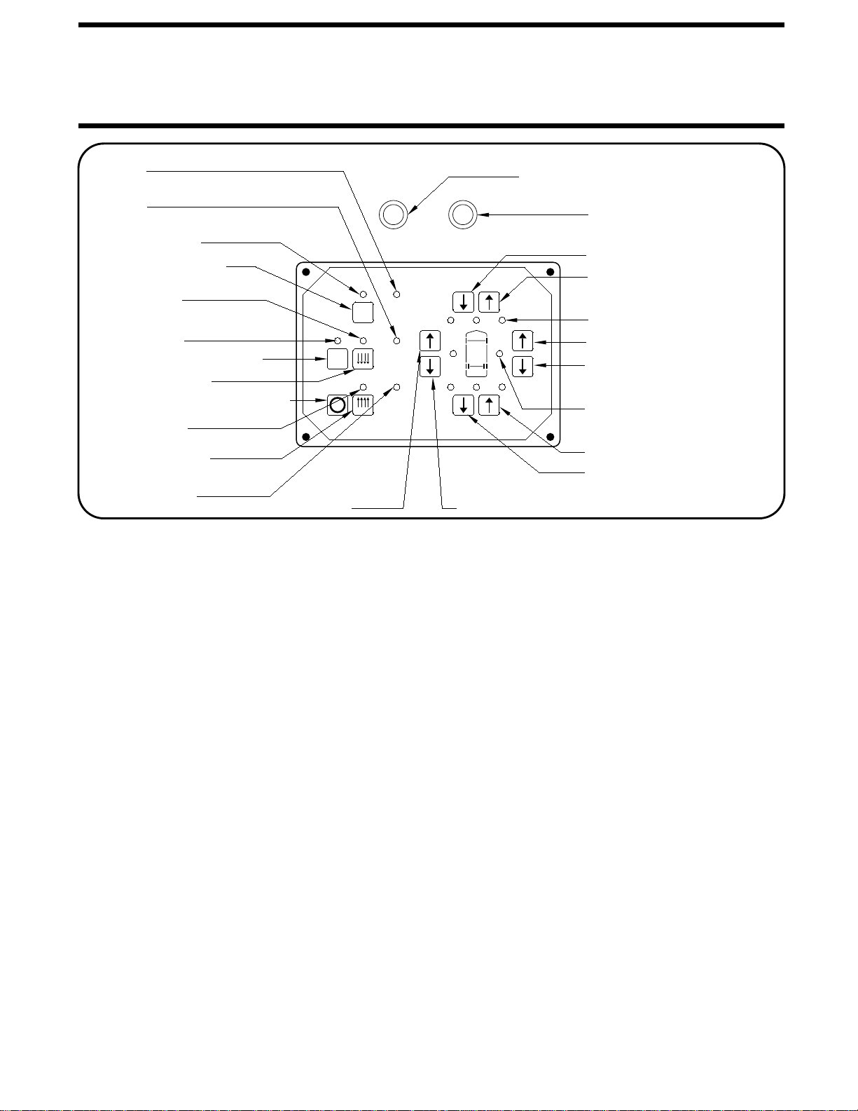
The green "TRAVEL MODE" light on the touch panel will not
be on if a room is extended or not locked. The MASTER
Visually check that the vehicle is at the proper ride height for
traveling.
The ignition must be in the "ON" position for the vehicle
suspension to be in the travel mode. Also the "TRAVEL
MODE" button must be pushed or the park brake released
for the suspension to be in the travel mode If the Leveling
CAUTION: IT IS THE OPERATOR’S
RESPONSIBILITY TO CHECK THAT THE VEHICLE IS AT
PROPER RIDE HEIGHT AND THE SLIDE-OUT IS FULLY
RETRACTED BEFORE TRAVELING.
Before traveling, the MASTER WARNING light must be off
and the "TRAVEL MODE" light must be ON.
NOTE: Low air pressure or an extended or unlocked
room can turn the green "TRAVEL MODE" light off and
turn the MASTER WARNING light on.
System was used.
A lit "TRAVEL MODE" light indicates that the HWH Leveling
System is in the TRAVEL MODE. It does not indicate that
the suspension is at ride height or that the coach is ready
to travel.
AUTOMATIC AIR OPERATION
will begin. The system will attempt to level the vehicle by
SYSTEM ACTIVE LIGHT will start flashing and air leveling
3. Press the "AIR" button a second time. The LEVELING
The "NOT IN PARK/BRAKE" light will be on while the
panel will not turn on if the park brake is not set.
ignition can be moved to the "OFF" position and the
use the "AIR" button. Once the operation is started, the
"AIR" button is being pushed.
NOTE: If the ignition key is in the "ON" position, the
NOTE: The ignition must be in the "ON" position to
leveling is complete.
When all four yellow LEVEL SENSING lights are out the
the vehicle will be raised by adding air to the air bags.
achieved by lowering the vehicle, the low side and/or end of
exhausting air from the air bags. If a level position is not
4. When all four yellow level lights are out, the LEVELING
SYSTEM ACTIVE LIGHT will stop flashing and start pulsating
dimly. The Leveling System is now in the SLEEP MODE.
operation will continue. If a ROOM CONTROL switch is
WARNING light will be ON. (SEE ROOM RETRACT
being pushed, the Leveling System can not be operated.
NOTE: Only one or two yellow LEVEL SENSING lights
may be ON at one time.
The vehicle’s engine/ignition may now be turned OFF.
6. If the vehicle needs to be releveled, the CAN Network will
become active. The LEVELING SYSTEM ACTIVE LIGHT
will flash. One or two yellow LEVELING LIGHTS will be ON.
When the yellow LEVELING LIGHTS are all out, the
LEVELING SYSTEM ACTIVE LIGHT will stop flashing and
start pulsating dimly. The Leveling System will remain in the
SLEEP MODE with the computer monitoring the LEVELING
SENSING UNIT every 30 minutes,
releveling the vehicle as needed.
Refer to "DUMP" and "RAISE" FUNCTIONS operating
procedures when moving the vehicle with the suspension
NOT at the proper ride height.
PROCEDURES)
5. During the Sleep Mode, after 30 minutes the processor
checks the Level Sensing Unit inputs. If no input for a yellow
level light is seen, the processor remains dormant and will
recheck the level unit inputs every thirty minutes. If a yellow
level light input is blinking, the processor will monitor the level
sensing unit inputs continuously. If the input stays off for one
minute, the processor reverts to checking the inputs every
30 minutes. If the input stays on for one minute continuously,
the processor will relevel the vehicle.
NOTE: Touch Panel Lights will not be ON unless the
system is actively leveling the vehicle.
1. Place the transmission in the proper position for parking
and set the park brake. The air leveling system can only be
turned on if the ignition is in the "ON" position. Leaving the
engine running during leveling is recommended. This will
provide a better air supply for leveling. The vehicle will level
with the engine shut off, however more time will be required
for leveling.
2. Press the "AIR" button once to enter the air mode. The
LEVELING SYSTEM ACTIVE LIGHT will glow steady. When
the ignition is in the "ON" position, the four red WARNING
lights on the panel will come on. This indicates that the
height control valves have been locked out. The vehicle
should not be moved when these lights are on.
NOTE: After the ignition and all room extension KEY
SWITCHES are turned OFF, the CAN Network stays
active for 10 minutes before shutting down. Leveling
System touch panel lights will stay ON during this time
and go out when the CAN Network shuts down. If the
Leveling System is in the SLEEP MODE when the
Network shuts down, the computer will stay ON. The
Leveling System touch panel lights will all be OFF, but
the Leveling System will still be in the SLEEP MODE.

OPERATING PROCEDURES
MP35.485P
14MAY01
AUTOMATIC AIR OPERATION (Continued)
The system will attempt to level the
vehicle for approximately 15 to 20 minutes. After the 15 to 20
minutes, if a LEVEL SENSING light is still on, the "EXCESS
SLOPE" light will come on. The LEVEL LIGHT indicator light
will go out. The "EXCESS SLOPE" light will be on whenever
SLOPE" light is on but they can be retracted.
The "EXCESS SLOPE" light will be on whenever the network
is active until the vehicle is leveled with all yellow LEVEL
indicator lights off.
Room extensions can not be extended if the "EXCESS
the network is active.
NOTE:
EXCESS SLOPE:NOTE:
The CAN Network will stay active for 10 minutes
after releveling the vehicle and then shut down, turning the
touch panel lights OFF. This happens every time the system
relevels the vehicle.
7. The SLEEP MODE will continue until the "EMERGENCY
STOP" button is pushed or the park brake is released, if the
ignition is in the "ON" position.
TAG AXLE DUMP
The tag axle dump switch is supplied by Foretravel.
IMPORTANT:Refer to Foretravel for proper use of the
TAG DUMP feature.
The tag dump switch will work only with the ignition switch
in the "ON" position and the Leveling System panel off.
NOTE: If the TAG DUMP switch is in the DUMP position and
the ignition key is turned ON (with the Leveling System panel
OFF) the tag axle air bags will go into the dump mode.
The TAG DUMP switch, in either the DUMP or TRAVEL
position, will not interfere with any air leveling operations.

OPERATING PROCEDURES
MP35.485Q
29JUL04
MANUAL AIR OPERATION
NOTE: The ignition must be in the "ON" or "ACC"
position to use the "AIR" button. Once the operation
is started, the ignition can be moved to the "OFF"
NOTE: If the "NOT IN PARK/BRAKE" light is on,
NOTE: If the "DUMP" or "RAISE" buttons are pushed
the leveling system cannot be turned on.
before leveling the vehicle front to rear.
The yellow LEVEL
indicator light indicates that side or end is low. When all yellow
lights are out the vehicle is level. Try leveling the vehicle by
while manually leveling the vehicle with air and the
ignition is in the "ON" position, the system will latch
into the dump or raise mode until the "EMERGENCY
STOP" button is pushed or the ignition is turned off.
4. Turn the ignition to the "OFF" position.
5. Turn the system off.
"DUMP" AND "RAISE" FUNCTIONS
CAUTION: REREAD CAUTIONS ON THE FIRST
PAGE OF THIS MANUAL. THE VEHICLE MAY DROP OR
RAISE AND/OR MOVE FORWARD OR BACKWARD
WITHOUT WARNING CAUSING INJURY OR DEATH.
THE AIR SUSPENSION IS AT THE PROPER
DO NOT OPERATE THE VEHICLE UNLESS
RESPONSIBILITY TO CHECK THAT THE VEHICLE
IS AT PROPER RIDE HEIGHT BEFORE TRAVELING.
CAUTION: IT IS THE OPERATOR’S
The "RAISE" and "DUMP" buttons can be used at any time
the network is active. The park brake does not have to be on.
If the ignition is in the "ON" position and the park brake is off,
the "RAISE" or "DUMP" buttons will latch in. The vehicle will
raise or lower completely and stay in that position.
The vehicle can not return to ride height until the "TRAVEL
MODE" button or the "EMERGENCY STOP" button is pushed
position and the operation will continue.
The "DUMP" and "RAISE" functions are provided for operator
convenience for purposes such as dumping the air
suspension when parked.
Leave the engine running if the "RAISE" function is to be
used. The park brake does not have to be set to use the
"DUMP" or "RAISE" buttons.
HEIGHT FOR TRAVEL.
or the vehicle exceeds 10 M.P.H, putting the system in the
TRAVEL MODE.
(up arrow) button to raise the low side or end.
lights). If a level position is not achieved use the RAISE
1. Place the transmission in the proper position for parking
and set the park brake. The air leveling system can only be
turned on if the ignition is in the "ON" position. Running the
vehicle engine during leveling is recommended. This will
provide a better air supply for leveling. The vehicle will level
with the engine shut off, however more time will be required
for leveling.
2. Press the "AIR" button once to enter the air mode. The
LEVELING SYSTEM ACTIVE LIGHT indicator light will glow
steady. When the ignition is in the "ON" position, the four red
WARNING lights on the panel will come on. This indicates
that the height control valves have been locked out. The
vehicle should not be moved when these lights are on.
IMPORTANT: If the ignition is ON and the park brake is
OFF, the "DUMP" and "RAISE" features will latch in and
remain on. If the vehicle exceeds 10 MPH, the "DUMP"
or "RAISE" functions will automatically turn off and the
system will return to the TRAVEL MODE. If the park
brake is set, the "TRAVEL MODE" button must be
pushed before the vehicle can return to ride height.
If the ignition is in the "OFF" position the "RAISE" and
"DUMP" buttons will not latch in. The vehicle will remain in
the position it was when the button was released. The
vehicle can return to ride height when the ignition is turned
to "ON" if the park brake is released or the "TRAVEL MODE"
button is pushed.
lowering the high side or end (opposite of the lit yellow level
3. The vehicle can now be leveled using the RAISE (up arrow)
and LOWER (down arrow) buttons on the right half of the
panel in conjunction with the yellow LEVEL indicator lights.
Any side to side leveling should be done, if needed,
NOTE: In either manual or automatic leveling when
either front air manifold air bag pressure switch is on
a front lower procedure is halted. When either rear air
manifold air bag pressure switch is on, a rear lower
procedure is halted. Air bag pressure switches will
not interfere with either a right or left lower procedure.
DO NOT operate the vehicle for extended distances
unless the air suspension is at the proper height for
travel. The vehicle can not return to ride height until
the "EMERGENCY STOP" button is pushed or the
vehicle exceeds 10 MPH, putting the system in the
TRAVEL MODE.

OPERATING PROCEDURES
MP35.905C
01DEC05
ROOM EXTEND PROCEDURE
1. The park brake must be set for the room to be operated.
If the "EXCESS SLOPE" light on the touch panel is on, the
room cannot be extended.
CAUTION:KEEP PEOPLE AND OBSTRUCTIONS
CLEAR OF ROOM WHEN OPERATING.
NOTE: Make sure there is adequate clearance to fully
extend the room.
2. Insert the KEY into the KEY SWITCH on the room
extension operator’s panel and turn it to the "ON" position.
The READY TO OPERATE light will flash. When the amber
light is on steady the room can be operated. light on the Leveling System panel is ON. The room
the room control switch is pushed if the "EXCESS SLOPE"
room will not extend. If the room panel KEY SWITCH is
NOTE: The READY TO OPERATE light will flash when
IMPORTANT: IF EITHER SIDE OF THE ROOM STOPS
MOVING, RELEASE THE ROOM CONTROL SWITCH
4. Turn the KEY SWITCH to the "OFF" position and remove
the key. The READY TO OPERATE light will go out. The air
IMMEDIATELY. THE ROOM OPERATION WILL HALT.
NOTE: Anytime the KEY SWITCH is on, the room air seal
seal will inflate.
will deflate.
on, the "READY TO OPERATE" light will flash while the
Leveling System is being operated.
NOTE: If the Leveling System is being operated, the NOTE: If the KEY SWITCH is left "ON" the air seal
will not inflate and the Network will stay active and not
DO NOT FORCE THE ROOM. DO NOT REVERSE
DIRECTION OF THE ROOM. BINDING OF ROOM CAN
CAUSE ROOM DAMAGE. CONTACT HWH CORPORATION
CUSTOMER SERVICE FOR ASSISTANCE.
NOTE: Under normal operation of the room, the direction
of movement should not be reversed. If the movement of
the room must be reversed, do not try to re-extend the
room until the room has been fully retracted.
IMPORTANT: If the "EXCESS SLOPE" light is ON, the
vehicle must be re-leveled so all yellow LEVEL indicator
lights on the touch panel are OFF before the room can be
extended. If any of the four yellow LEVEL indicator lights
cannot be put out, the vehicle should be moved to a
more level location before using the room extension.
power down.
will not extend.
Make sure the door or a window is open while extending
a room.
than 10 seconds) before the PUMP ON light comes on after
the red PUMP ON light goes out.
release the room control switch.
remains on 30 seconds after the room is fully extended
go out. Do not release the ROOM CONTROL SWITCH, until
pump will automatically shut off. The red PUMP ON light will
the switch is pushed. When the room is fully extended, the
If the red PUMP ON light
3. To extend the room, push and hold the ROOM CONTROL
come on. There may be a delay of several seconds (no more
SWITCH in the extend position. The red PUMP ON light will
The Room Control switch will not work until the vacuum
the room unless the Room Control switch is released.
of vacuum in the air seal will not halt the movement of
While the Room Control Switch is being pushed a loss
operation when the Room Control switch is pushed.
air seal is deflated. This may cause a delay in room
seal is monitored by a vacuum switch to make sure the
NOTE: The room is equipped with an air seal, the air
switch is made.
the vehicle before extending the room.
IMPORTANT: It is recommended to level

OPERATING PROCEDURES
ROOM RETRACT PROCEDURE
CAUTION:
KEEP PEOPLE AND OBSTRUCTIONS
CLEAR OF ROOM WHEN OPERATING.
1. The park brake must be set for the room to be operated.
2. Insert the KEY into the KEY SWITCH on the room
extension operator’s panel and turn it to the "ON" position.
The air seal will deflate. The READY TO OPERATE light
will flash. When the amber light is on steady the room can
3. To retract the room, push and hold the ROOM CONTROL
SWITCH in the "RETRACT" position. The red PUMP ON light
will come on. When the room is fully retracted, the pump will
automatically shut off. The red PUMP ON light will go out.
Do not release the ROOM CONTROL SWITCH until the red
4. Turn the KEY SWITCH to the "OFF" position and remove
the key. The READY TO OPERATE light will go out. The air
IN THE EVENT OF THE FAILURE OF THE ROOM TO
RETRACT, CONTACT HWH CORPORATION CUSTOMER
SERVICE AT 1-800-321-3494 FOR ASSISTANCE.
seal will inflate.
be operated.
NOTE: (FOR ROOMS WITH HWH LOCKS) If the ROOM
CONTROL SWITCH is released before the red PUMP ON
light goes out, the room may not be properly locked.
The transmission will not shift out of "NEUTRAL".
not inflate and the Network will stay active and not
NOTE: If the KEY SWITCH is left "ON" the air seal will
NOTE: If the Leveling System is being operated, the
room will not retract. If the room panel KEY SWITCH is
ON, the READY TO OPERATE light will flash while the
Leveling System is being operated.
PUMP ON light goes out.
CAUSE ROOM DAMAGE. CONTACT HWH CORPORATION
CUSTOMER SERVICE FOR ASSISTANCE.
DIRECTION OF THE ROOM. BINDING OF ROOM CAN
DO NOT FORCE THE ROOM. DO NOT REVERSE
IMMEDIATELY. THE ROOM OPERATION WILL HALT.
MOVING, RELEASE THE ROOM CONTROL SWITCH
IMPORTANT: IF EITHER SIDE OF THE ROOM STOPS
NOTE: Under normal operation the direction of
movement should not be reversed. If the movement of
the room must be reversed, do not try to retract the
room until the room has been fully extended.
remains on 30 seconds after the room is fully retracted
If the red PUMP ON light
release the room control switch.
IMPORTANT: It is recommended that the coach is level
before retracting the room.
MP35.907C
15APR04
power down.

MP35.952D
01MAY02
MANUAL ROOM AND GENERATOR SLIDE RETRACT PROCEDURE
OVERVIEW
1. Retract jacks following the LEVELING SYSTEM
RETRACT PROCEDURE.
2. Locate the HYDRAULIC PUMP/MANIFOLD unit.
VALVES are opened and internal pressure is released.
WINCH
WINCH STRAP
WINCH HANDLE
RATCHET LEVER
HOOK
MANUAL RETRACT WINCH
5. Slowly winch the room in by turning the WINCH HANDLE
clockwise. The RATCHET LEVER should produce a loud, sharp,
clicking noise.
in the hydraulic fluid and make winching more difficult.
CAUTION:
ON
OFF
HYDRAULIC PUMP/MANIFOLD
NOTE: The room may move slightly as the SOLENOID
NOTE :
NOTE: Winching the room in quickly will raise pressure
IMPORTANT:
6. When the room is fully retracted, engage the room locking
devices. Leave the retract winch engaged and the solenoid
CAUTION: THE ROOM EXTENSION SOLENOID
VALVE RELEASE NUTS MUST BE IN THE OPEN
POSITION WHEN THE MANUAL RETRACT WINCH IS
7. The system should be repaired before using again.
CAUTION: THE MANUAL RETRACT WINCH IS
OPERATE THE MANUAL RETRACT
WINCH BY HAND POWER ONLY. IF THE WINCH
CANNOT BE CRANKED EASILY WITH ONE HAND IT IS
PROBABLY OVERLOADED. IF WINCHING BECOMES
TOO DIFFICULT STOP AND CHECK FOR OBSTRUCTIONS
OR RESTRICTIONS ON THE ROOM AND ROOM
LEVELING SYSTEM MANIFOLD NOT SHOWN
SOLENOID VALVES
VALVE
RELEASE
NUT NUT
VALVE
RELEASE
3. Open the Solenoid Valves by slowly turning the valve
release nuts counter clockwise using the 1/4" nut driver
Only open the valves enough to retract NOTE: After repairs are made, when
closing the VALVE RELEASE NUTS, do
When manually retracting the room, make sure
the jacks are retracted before retracting the room.
EQUIPPED FOR MANUALLY RETRACTING THE ROOM
ONLY. IT IS NOT TO BE USED FOR LIFTING OR ANY
OTHER APPLICATION. HIGH FORCES ARE CREATED
WHEN USING A WINCH, CREATING POTENTIAL SAFETY
HAZARDS. FAILURE TO FOLLOW ALL CAUTIONS AND
INSTRUCTIONS MAY CAUSE FAILURE OF THE MANUAL
RETRACT WINCH OR CONNECTIONS RESULTING IN
DAMAGE OR PERSONAL INJURY. MAINTAIN FIRM GRIP
ON THE WINCH HANDLE AT ALL TIMES. NEVER
RELEASE THE HANDLE WHEN RATCHET LEVER IS IN
THE OFF POSITION AND THE WINCH IS LOADED. THE
WINCH HANDLE COULD SPIN VIOLENTLY AND CAUSE
PERSONAL INJURY. CHECK THE WINCH AND STRAPS
FOR DAMAGE OR WEAR, AND CHECK FOR PROPER
RATCHET OPERATION ON EACH USE OF THE WINCH.
DO NOT USE IF DAMAGED OR WORN.
supplied.
the room. DO NOT turn the release nuts more than
4 and 1/2 turns. Turning the nuts more could damage
the valves.
with the Operators Manual. As of APRIL 2002 the
NOTE: Prior to APRIL 2002 a 1/4" Nut Driver was sent
Cap. See the back page of this manual for further info.
1/4" Nut Driver has been incorporated into the Breather
4. Locate the MANUAL RETRACT WINCH and connect
it to the room according to the vehicle manufacturer’s
instructions. To extend the WINCH STRAP firmly grasp
WINCH HANDLE, place RATCHET LEVER in its OFF
position, and slowly rotate the WINCH HANDLE
counter clockwise, keeping a firm grip on the handle. When
enough WINCH STRAP is extended, place the RATCHET
LEVER in its ON position and slowly rotate the WINCH
HANDLE clockwise until the RATCHET LEVER locks.
EXTENSION MECHANISM.
valves open.
ENGAGED.
(WITH SOLENOID VALVES WITH VALVE RELEASE NUTS)
(USE ONLY WHEN THE ROOM WILL NOT RETRACT WITH THE ROOM CONTROL SWITCH)
not over tighten the nuts.
IMPORTANT: If the vehicle is not equipped with a winch,
DO NOT use other pulling devices to retract the room.
Follow steps 2 and 3 and try pushing the room in.
Contact the vehicle manufacturer or HWH Customer
Service at 1-800-321-3494 or 563-724-3396 for assistance.
The room can be retracted manually if a hydraulic or electric
failure prevents the room from being retracted using the
CONTROL SWITCH. For normal retract sequence see the
ROOM SLIDE RETRACT PROCEDURES. Refer to the
vehicle manufacturer for storage location of the winch
and information for connecting the winch to the room.

OPERATING PROCEDURES
MP36.109A
31MAY02
2. Turn the room extension control panel key to "ON".
5. After 20 seconds, the amber "READY TO OPERATE"
light will be on steady. The room cannot be operated if the
"READY TO OPERATE" light is flashing.
6. Push the Room Extension Control Switch to "EXTEND".
This will send a +12 signal for the pump relay and the room
extension solenoid valves from the control modules. A +12
NOTE: The room control switch must be held in the
"EXTEND" position during the extend sequence. If the
room control switch is released before the sequence is
complete, the sequence will start over from Step 6 when
the switch is pushed to extend again.
7. A +12 signal will open the room unlock valve. This valve
will stay open during the complete extend sequence.
8. When the room lock pins are fully retracted, the room
unlock limit switch arrangement will send a +12 volt signal
to the room module. The manifold pressure switch will send
a ground signal to the central control module when pump
pressure reaches 3000 psi. The sequence will not continue
until both signals are received by their modules.
9. When both the room unlock limit switches and the manifold
pressure switch signals are received by their modules, a +12
signal will open the room extend solenoid valve.
10. When the room is fully extended, the room out limit
switch arrangement sends a ground signal to the room
module. The manifold pressure switch sends a ground
signal to the central control module when the pump
pressure reaches 3000 psi. The sequence will continue
when both signals are received by their modules.
11. When both the room out limit switches and the manifold
pressure switch signals are received by the modules, the +12
signal to the room extend valve is turned off. The extend
sequence is finished and the pump will shut off.
The room control switch may be released.
12. The red pump on light will go out.
NOTE: The unlock valve will stay open for 10 seconds
after the pump shuts off, even if the room control switch
13. The air seal will inflate when the room control key switch
is turned off. The amber light on the room control panel will
go out.
IMPORTANT: MAKE SURE A WINDOW OR DOOR IS
OPEN BEFORE EXTENDING THE ROOM.
1. Park brake must be set.
signal turns the room control panel red pump on light ON
when the pump is running.
3. The amber "READY TO OPERATE" light will flash.
A +12 signal controls the "READY TO OPERATE LIGHT".
4. Any time the room extension key is ON, there is a +12
volt signal to the air seal valve. There is also a +12 volt
signal to the vacuum valve which is not constant. The +12
signal for the vacuum valve is present during the initial 20
second air seal deflate time, anytime the room control switch
is pushed to "EXTEND" or "RETRACT", or if the air seal
manifold is equipped with a vacuum switch, anytime the
vacuum switch is not made.
is released.
NOTE: The room extend valve will be
the cylinder retract valve.
ROOM EXTENSION OPERATION SEQUENCE
ROOM EXTEND SEQUENCE
FRONT ROOM

OPERATING PROCEDURES
MP36.109B
31MAY02
2. Turn the room extension control panel key to "ON".
5. After 20 seconds, the amber "READY TO OPERATE"
light will be on steady. The room cannot be operated if the
"READY TO OPERATE" light is flashing.
6. Push the Room Extension Control Switch to "RETRACT".
This will send a +12 signal for the pump relay and the room
extension solenoid valves from the control modules. A +12
NOTE: The room control switch must be held in the
"RETRACT" position during the retract sequence. If the
room control switch is released before the sequence is
complete, the sequence will start over from Step 6 when
the switch is pushed to retract again.
7. A +12 signal will open the room unlock valve. This valve
8. When the room lock pins are fully retracted, the room
unlock limit switch arrangement will send a +12 volt signal
to the room module. The manifold pressure switch will send
a ground signal to the central control module when pump
pressure reaches 3000 psi. The sequence will not continue
until both signals are received by their modules.
9. When both the room lock limit switches and the manifold
pressure switch signals are received by their modules, a +12
signal will open the room retract solenoid valve.
10. When the room is fully retracted, the room in limit
switch arrangement sends a ground signal to the room
module. The manifold pressure switch sends a ground
signal to the central control module when the pump
pressure reaches 3000 psi. The sequence will continue
when both signals are received by their modules.
11. When both the room in limit switches and the manifold
pressure switch signals are received by their modules, the +12
12. A +12 signal opens the room lock valve.
IMPORTANT: MAKE SURE A WINDOW OR DOOR IS
OPEN BEFORE EXTENDING THE ROOM.
1. Park brake must be set.
signal turns the room control panel red pump on light ON
when the pump is running.
3. The amber "READY TO OPERATE" light will flash.
A +12 signal controls the "READY TO OPERATE LIGHT".
4. Any time the room extension key is ON, there is a +12
volt signal to the air seal valve. There is also a +12 volt
signal to the vacuum valve which is not constant. The +12
signal for the vacuum valve is present during the initial 20
second air seal deflate time, anytime the room control switch
is pushed to "EXTEND" or "RETRACT", or if the air seal
manifold is equipped with a vacuum switch, anytime the
vacuum switch is not made.
will stay open until the room is fully retracted.
NOTE: The room can be retracted if the "READY TO
OPERATE" light is flashing due to the "EXCESS SLOPE"
light on the leveling system panel being on.
signal to the room unlock valve is turned off and the unlock
valve closes.
13. When the room lock pins are fully extended, the room lock
limit switch arrangement sends a +12 signal to the room
module. The manifold pressure switch sends a ground signal
to the central control module when pump pressure reaches
3000 psi.
14. When both the room lock limit switches and the manifold
pressure switch signals are received by their modules, the
pump will shut off. The red pump on light will shut off and the
sequence is complete. The room control switch may be re-
leased.
NOTE: Do Not release the room control switch until
the "PUMP ON" light goes out.
15. The air seal will inflate when the room control key switch
is turned off. The amber light on the room control panel will
go out.
NOTE: Even though the room does not lock in the
extended position, the system checks to make sure the
locks are fully retracted before proceeding.
FRONT ROOM
ROOM RETRACT SEQUENCE
ROOM EXTENSION OPERATION SEQUENCE
the cylinder extend valve.
NOTE: The room retract valve will be

OPERATING PROCEDURES
MP36.109M
03JUN02
ROOM EXTENSION OPERATION SEQUENCE
ROOM EXTEND SEQUENCE
2. Turn the room extension control panel key to "ON".
5. After 20 seconds, the amber "READY TO OPERATE"
light will be on steady. The room cannot be operated if the
"READY TO OPERATE" light is flashing.
6. Push the Room Extension Control Switch to "EXTEND".
This will send a +12 signal for the pump relay and the room
extension solenoid valves from the control modules. A +12
NOTE: The room control switch must be held in the
"EXTEND" position during the extend sequence. If the
room control switch is released before the sequence is
complete, the sequence will start over from Step 6 when
the switch is pushed to extend again.
7. A +12 signal will open the room unlock valve. This valve
will stay open during the complete extend sequence.
8. When the room lock pins are fully retracted, the room
unlock limit switch arrangement will send a +12 volt signal
to the room module. The manifold pressure switch will send
a ground signal to the central control module when pump
pressure reaches 3000 psi. The sequence will not continue
until both signals are received by their modules.
9. When both the room unlock limit switches and the manifold
pressure switch signals are received by their modules, a +12
signal will open the room extend solenoid valve.
10. When the room is fully extended, the room out limit
switch arrangement sends a ground signal to the room
module. The manifold pressure switch sends a ground
signal to the central control module when the pump
pressure reaches 3000 psi. The sequence will continue
when both signals are received by their modules.
11. When both the room out limit switches and the manifold
pressure switch signals are received by the modules, the +12
signal to the room extend valve is turned off. The extend
sequence is finished and the pump will shut off.
The room control switch may be released.
12. The red pump on light will go out.
NOTE: The unlock valve will stay open for 10 seconds
after the pump shuts off, even if the room control switch
13. The air seal will inflate when the room control key switch
is turned off. The amber light on the room control panel will
go out.
IMPORTANT: MAKE SURE A WINDOW OR DOOR IS
OPEN BEFORE EXTENDING THE ROOM.
1. Park brake must be set.
signal turns the room control panel red pump on light ON
when the pump is running.
3. The amber "READY TO OPERATE" light will flash.
A +12 signal controls the "READY TO OPERATE LIGHT".
4. Any time the room extension key is ON, there is a +12
volt signal to the air seal valve. There is also a +12 volt
signal to the vacuum valve which is not constant. The +12
signal for the vacuum valve is present during the initial 20
second air seal deflate time, anytime the room control switch
is pushed to "EXTEND" or "RETRACT", or if the air seal
manifold is equipped with a vacuum switch, anytime the
vacuum switch is not made.
is released.
BEDROOM
NOTE: The room extend valve will be
the cylinder extend valve.

OPERATING PROCEDURES
MP36.109N
03JUN02
2. Turn the room extension control panel key to "ON".
5. After 20 seconds, the amber "READY TO OPERATE"
light will be on steady. The room cannot be operated if the
"READY TO OPERATE" light is flashing.
6. Push the Room Extension Control Switch to "RETRACT".
This will send a +12 signal for the pump relay and the room
extension solenoid valves from the control modules. A +12
NOTE: The room control switch must be held in the
"RETRACT" position during the retract sequence. If the
room control switch is released before the sequence is
complete, the sequence will start over from Step 6 when
the switch is pushed to retract again.
7. A +12 signal will open the room unlock valve. This valve
8. When the room lock pins are fully retracted, the room
unlock limit switch arrangement will send a +12 volt signal
to the room module. The manifold pressure switch will send
a ground signal to the central control module when pump
pressure reaches 3000 psi. The sequence will not continue
until both signals are received by their modules.
9. When both the room lock limit switches and the manifold
pressure switch signals are received by their modules, a +12
signal will open the room retract solenoid valve.
10. When the room is fully retracted, the room in limit
switch arrangement sends a ground signal to the room
module. The manifold pressure switch sends a ground
signal to the central control module when the pump
pressure reaches 3000 psi. The sequence will continue
when both signals are received by their modules.
11. When both the room in limit switches and the manifold
pressure switch signals are received by their modules, the +12
12. A +12 signal opens the room lock valve.
IMPORTANT: MAKE SURE A WINDOW OR DOOR IS
OPEN BEFORE EXTENDING THE ROOM.
1. Park brake must be set.
signal turns the room control panel red pump on light ON
when the pump is running.
3. The amber "READY TO OPERATE" light will flash.
A +12 signal controls the "READY TO OPERATE LIGHT".
4. Any time the room extension key is ON, there is a +12
volt signal to the air seal valve. There is also a +12 volt
signal to the vacuum valve which is not constant. The +12
signal for the vacuum valve is present during the initial 20
second air seal deflate time, anytime the room control switch
is pushed to "EXTEND" or "RETRACT", or if the air seal
manifold is equipped with a vacuum switch, anytime the
vacuum switch is not made.
will stay open until the room is fully retracted.
NOTE: The room can be retracted if the "READY TO
OPERATE" light is flashing due to the "EXCESS SLOPE"
light on the leveling system panel being on.
signal to the room unlock valve is turned off and the unlock
valve closes.
13. When the room lock pins are fully extended, the room lock
limit switch arrangement sends a +12 signal to the room
module. The manifold pressure switch sends a ground signal
to the central control module when pump pressure reaches
3000 psi.
14. When both the room lock limit switches and the manifold
pressure switch signals are received by their modules, the
pump will shut off. The red pump on light will shut off and the
sequence is complete. The room control switch may be re-
leased.
NOTE: Do Not release the room control switch until
the "PUMP ON" light goes out.
15. The air seal will inflate when the room control key switch
is turned off. The amber light on the room control panel will
go out.
NOTE: Even though the room does not lock in the
extended position, the system checks to make sure the
locks are fully retracted before proceeding.
BEDROOM
ROOM RETRACT SEQUENCE
ROOM EXTENSION OPERATION SEQUENCE
the cylinder retract valve.
NOTE: The room retract valve will be

MP45.998C
29NOV05
MAINTENANCE
OIL LEVEL
FLUID: HWH Specialty Hydraulic Oil is recommended. In an
brake fluid or hydraulic jack fluid. Use of these can damage
and can cause staining should a leak occur. DO NOT USE
Dexron automatic transmission fluid contains red dye
emergency Dexron automatic transmission fluid can be used.
seals.
NOTE:
It is important that all front rooms are fully retracted before
checking the hydraulic oil level. If the coach has a bed slide,
the bed slide must be fully retracted before checking the
hydraulic oil level. If the coach has a wardrobe slide, the
wardrobe slide must be fully extended before checking the
hydraulic oil level. To check the oil supply, remove the
breather cap from the top of the hydraulic oil reservoir.
The oil level should be approximately one inch below the
top of the reservoir when adequately filled.

MP65.931C
21MAY02
HYDRAULIC LINE CONNECTION DIAGRAM
FRONT ROOM - TRAIN DRIVE ROOM EXTENSION - 4 ROOM LOCKS
(WITH SYNCHRONIZING CYLINDER)
1 - FRONT ROOM CYLINDER EXTEND VALVE
2 - FRONT ROOM CYLINDER RETRACT VALVE
3 - FRONT ROOM LOCK VALVE
4 - FRONT ROOM UNLOCK VALVE 4
2
3
1
CAP END
ROD END CAP END
ROD END
ROD END
CAP END ROD END
CAP END
VIEW FROM INSIDE VEHICLE
(A) HOSES MUST MAINTAIN EQUAL
(B) HOSES MUST BE
HIGH PRESSURE HOSE AND
PRESS
SW 5000
P.S.I. (4)
R F
BACK PRESSURE VALVE
REAR (R) AND FRONT (F)
INTEGRITY OF BACK PRESS.
VALVE TO CYLINDERS
MUST BE MAINTAINED.
UPPER REAR (R) CYLINDER UPPER FRONT (F) CYLINDER
LOWER REAR (R) CYLINDER LOWER FRONT (F) CYLINDER
LENGTH AND DIAMETER.
MAINTAIN EQUAL LENGTH AND DIAMETER.
HIGH PRESSURE HOSE AND
(D) HOSES MUST BE
LENGTH AND DIAMETER.
(C) HOSES MUST MAINTAIN EQUAL
ROD END
(A1)
(B1)
(D1) (D2)
(C2)
CAP
END
END
ROD
(B2)
(A2)
(C1)
HOSE TO FITTING CONNECTIONS AT
(A1) BLUE/GREEN
(A2) ORANGE/YELLOW
(C1) YELLOW/BLUE
(C2) GREEN/ORANGE
(B1) BLUE
(D1) YELLOW
(B2) ORANGE
(D2) GREEN
SYNC. CYL. ARE COLOR CODED.
CAP
END
END
ROD
VALVE
RELEASE
NUTS
SEE PAGE MP65.931E
FOR LOCK CONNECTION
INFORMATION
CYLINDER EXTEND - ROOM RETRACT
CYLINDER RETRACT - ROOM EXTEND
PRESSURE SW. 3000 P.S.I.

MP65.931E
09JAN04
HYDRAULIC LINE CONNECTION DIAGRAM
FRONT ROOM - TRAIN DRIVE ROOM EXTENSION - 4 ROOM LOCKS
(WITH SYNCHRONIZING CYLINDER)
43
VIEW FROM INSIDE VEHICLE
LOWER REAR
ROOM LOCK
CAP
END
END
ROD
VALVE
RELEASE
NUTS
ROOM LOCK
UPPER REAR UPPER FRONT
ROOM LOCK
LOWER FRONT
ROOM LOCK
ROD END
CAP END
ROD END CAP
END
END
CAP
ROD END
CAP END
ROD END
PRESSURE SW. 3000 P.S.I.

MP65.942P
29APR02
HYDRAULIC LINE CONNECTION DIAGRAM
REAR SINGLE CYLINDER "GUIDED" ROOM EXTENSION - 4 ROOM LOCKS
UPPER
ROOM
LOCK
UPPER
ROOM
LOCK
CAP
END CAP
END
ROD
END END
ROD
NOTE: THE ROD END CONNECTION
FROM THE MANIFOLD TO THE ROOM
CYLINDER IS ALWAYS PRESSURIZED.
ROD
END
CAP
END
LOWER
ROOM
LOCK
END
ROD
END
CAP
ROOM
LOWER
LOCK
ROD CONNECTIONS TO ROOM LOCKS
WILL NOT BE PRESSURIZED.
5 - REAR ROOM CYLINDER EXTEND VALVE
6 - REAR ROOM CYLINDER RETRACT VALVE
7 - REAR ROOM LOCK VALVE
8 - REAR ROOM UNLOCK VALVE
8
67
5
VALVE RELEASE NUTS
OIL FILL/
BREATHER
CAP
ROD END
CONNECTION
CAP END
CONNECTION
PRESS. SW.
3000 P.S.I.
BEDROOM SLIDE
CYLINDER RETRACT - ROOM RETRACT
CYLINDER EXTEND - ROOM EXTEND
Other manuals for 2000 SERIES
8
Table of contents
Other HWH Industrial Equipment manuals
Popular Industrial Equipment manuals by other brands

Aero-motive
Aero-motive Woodhead BF Series Service manual

HIK VISION
HIK VISION DS-K3B601SX Series quick start guide

Flex-A-Seal
Flex-A-Seal Style 58 Installation, operation, maintenance guide

Alfalaval
Alfalaval AlfaNova 76 instruction manual

Avantco
Avantco Leguan 50 Operator's manual for Attachment

Alfalaval
Alfalaval RV-P instruction manual