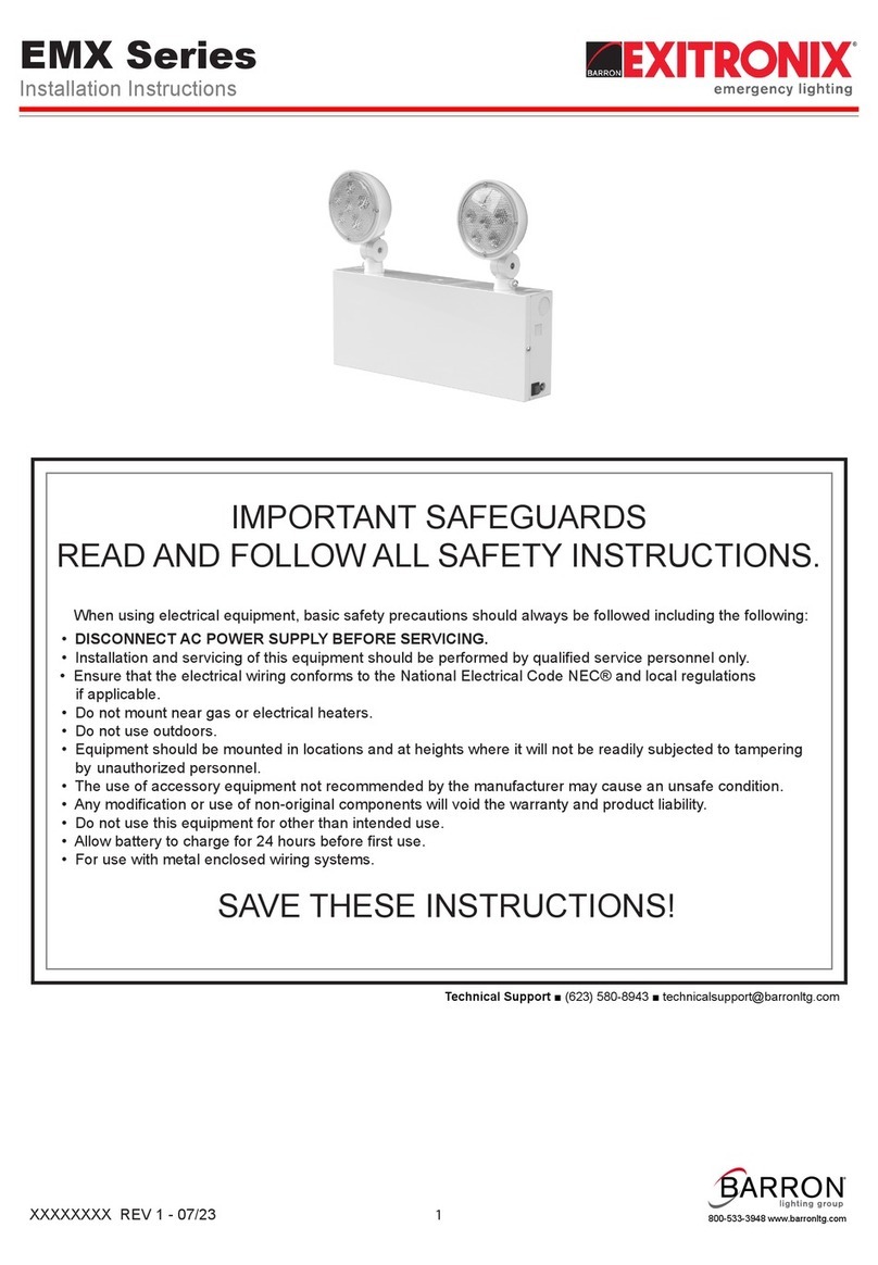
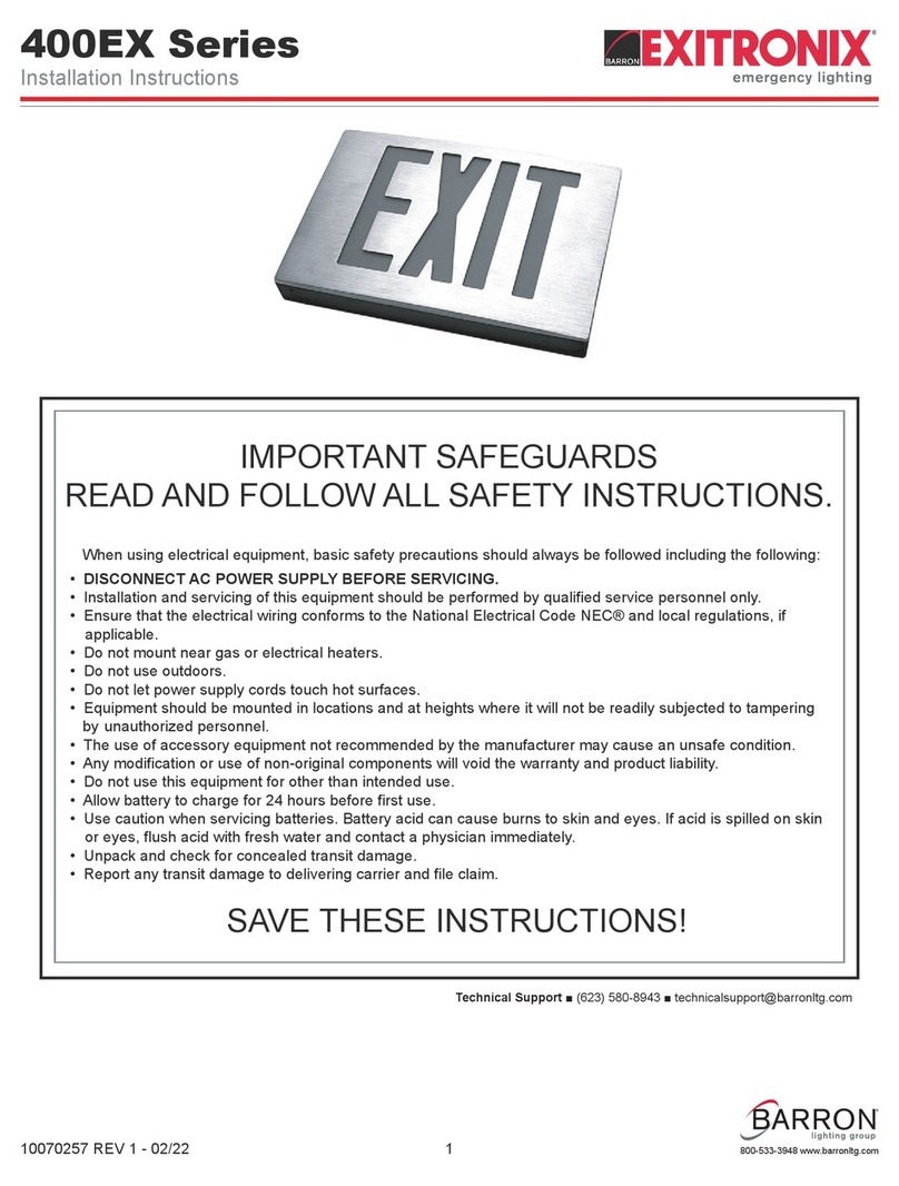
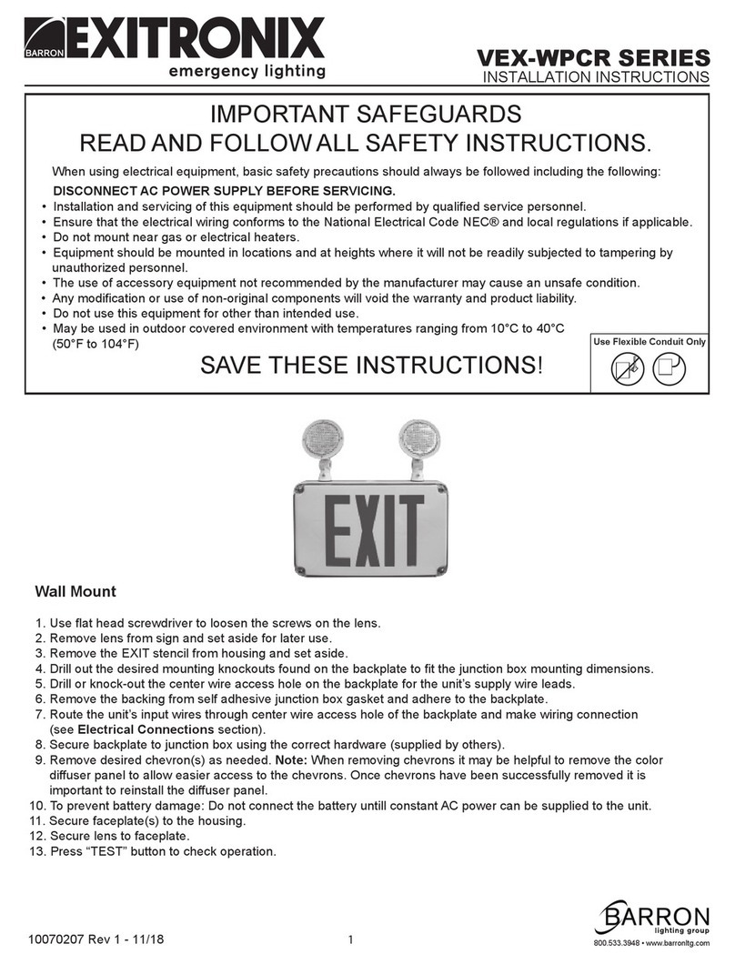
Exitronix S902 Series User manual

IMPORTANT SAFEGUARDS
READ AND FOLLOW ALL SAFETY INSTRUCTIONS.
When using electrical equipment, basic safety precautions should always be followed including the following:
• DISCONNECT AC POWER SUPPLY BEFORE SERVICING.
• Installation and servicing of this equipment should be performed by qualified service personnel only.
• Ensure that the electrical wiring conforms to the National Electrical Code NEC® and local regulations
if applicable.
• Do not mount near gas or electrical heaters.
• Do not use outdoors.
• Equipment should be mounted in locations and at heights where it will not be readily subjected to tampering
by unauthorized personnel.
• The use of accessory equipment not recommended by the manufacturer may cause an unsafe condition.
• Any modification or use of non-original components will void the warranty and product liability.
• Do not use this equipment for other than intended use.
• Allow battery to charge for 24 hours before first use.
• For use with metal enclosed wiring systems.
SAVE THESE INSTRUCTIONS!
Technical Support ■ (623) 580-8943 ■ [email protected]
S902/S903 Series
Installation Instructions
XXXXXXXX REV 6 - 07/23 1
800-533-3948 www.barronltg.com

Fig. 1
Fig. 2
Fig. 3 Fig. 4
Fig. 5
Fig. 6
Fig. 7 Fig. 8
Antenna
LED bushing
Test switch
Switch connector
Screws
Test switch
LED bushing
End cap
(test switch side)
LED indicator
Test switch
connector
LED indicator
connector
Antenna connector
Antenna
connector
Antenna
extend wire
Test switch
connector
LED indicator
connector
Screws for trim plate
Trim plate
Test switch
Antenna
connector
S902/S903 Series
Installation Instructions
XXXXXXXX REV 6 - 07/23 2
800-533-3948 www.barronltg.com
Recessed Ceiling Installation
1. Open front cover by blade screw driver, attach battery
connector on PCBA, disassemble J-box cover, punch out
wire hole. Secure J-box on the top of fixture by screws,
feed the AC wires out of J-box cover. Restore J-box cover,
restore front cover. (Fig. 1)
2. Unscrew and remove test switch side end cap, disconnect
test switch connector, remove test switch and LED
indicator and bushing from end cap, disassemble antenna
connector and feed test switch,LED indicator and antenna
wire out of end cap, restore end cap on housing by
screws. Connect antenna extend wire (provided in
accessories bag) on antenna connector. (Fig. 2)
3. Assemble test switch, LED bushing and LED indicator on
the trim plate. Assemble antenna on trim plate. (Fig. 3)
4. Position recessed kits and bar hangers between joists.
Make sure bar hangers to be hanged in correct position.
Position recessed kits temporarily by hammering “nail-in”
tabs on bar hangers, then secure permanently with nails.
Note: Bar hangers should be level with bottom of joists.
5. Adjust height of recessed kits vertically using adjusting slots
and then tighten all screws on adjusting slots and bar
hanger bracket to secure adjusting bracket and bar
hangers. (Fig. 4)
6. Make AC supply wiring, white wire for neutral, black wire for
120VAC Input, orange wire for 277VAC Input, green wire for
grounding. After wiring, get wire nuts inside of J-box. (Fig.
5)
7. Peel off protection film from EXIT panel. Insert EXIT panel
into main body assembly gently. (Fig. 6)
Note: If EXIT panel is for single face, make sure EXIT
letter direction is right.
8. Insert fixture into hanger bracket and snap by spring,
connect test switch, LED indicator and antenna connector,
fix trim plate on the metal box by 2 screws. (Fig. 7)
9. Determine direction for chevron indicator.
Note: Refer to Chevron Placement section.
Recessed Wall Installation
1. Reference steps 1-9 in recessed ceiling installation above
for recessed wall mounting.
2. Acrylic panel can rotate 90° to become recessed wall
installation. (Fig. 8)

Fig. 9
Fig. 10
S902/S903 Series
Installation Instructions
XXXXXXXX REV 6 - 07/23 3
800-533-3948 www.barronltg.com
Chevron Placement (Fig. 9)
• If chevron is needed remove only the instruction film.
• If no chevron is needed, remove both the instruction film
and chevron together.
Wiring Diagram (Fig. 10)
Note: Cap off the UNUSED input lead. Failure to do so can cause an unsafe operating condition.
Operation
The battery in this unit may not be fully charged. After electricity is connected to the unit for at least 24 hours, then normal
operation of this unit should take effect. To check, press the “TEST” button. The EXIT sign should stay illuminated.
In accordance with NFPA 101, your emergency lighting system must be tested monthly for a minimum of 30 seconds and
annually for 90 minutes. Refer to your local codes for any additional requirements that may apply.
Testing and Reporting Instructions (-G2 and -G3 models)
1. When AC power is supplied to fixture, the unity will automatically initiate a self-test and self-diagnostic test as follows:
• Verifies battery disconnection, charger board failure at every 5 seconds.
• 1 minute self-testing every month.
• 30 minutes self-testing on every 6 months after installation.
• 90 minutes self-testing on every 12 months after installation.
2. Dual color LED lamp indicator shows the following status:
• Green color: On / Ready
blinking: Testing
• Red color: (Service Alert)
• Service Alert LED Code (Red color LED lamp indicator)
Note: After solving the fault of emergency equipment, please press test button for 2 seconds then release to
reset. LED indicator will show green.
●
● ●
● ● ●
● ● ● ●
One blink,
Two blinks,
Three blinks,
Four blinks,
4 second pause Battery is not connected
Battery voltage too low
Charger board circuit failure
Transfer function failure
4 second pause
4 second pause
4 second pause
● ● ● ● ● ● ● Seven blinks, 4 second pause
LED strip failure

Fig. 11
Fig. 12
Jump connector
Extended remote wire
Remote wire
(provided)
Jump connector
Remote head
connector
Remote head
connector
S902/S903 Series
Installation Instructions
XXXXXXXX REV 6 - 07/23 4
800-533-3948 www.barronltg.com
3. “-G2” and “-G3” models also have a manual test function, press test button as follows:
Networking Operations for “-G3” Models
Model with "-G3" suffix is our world winning design equipped with "wireless testing and reporting" features. Unit that
has "-G3" suffix in its model number is capable of joining Guardian emergency lighting management system. It will be
part of a large testing system to be tested and report result wirelessly.
Once powered up and commissioning allowed, unit will automatically join Guardian network and get provisioned. Upon
the completion of the commissioning,unit will perform testing and report based on set schedules.
For more information about commissioning, configurations and testing, please visit website, https://www.barronltg.com
for details.
If you have problem to initiate provisioning or if you know the unit belongs to other Guardian network. Please follow the
instructions below to reset the fixture and make it in a factory state:
• Press and hold the test button for over 8 seconds, and the fixture will leave the network and reset itself.
Remote Heads Connection Instructions (Option)
1. Remove jump connector from the female connector on
PCBA. (Fig. 11)
2. Attach the remote male connector into the female
connector on PC board.
3. Connect extended remote head wires to the remote
wires using wire nuts. Yellow is positive (+) and the
purple is negative (-). (Fig. 12)
Press test button once
Press test button twice within 2 seconds
Press test button 3 times within 2 seconds
Press test button 4 times within 2 seconds
3 minutes discharge test
30 minutes discharge test
90 minutes discharge test
30 seconds discharge test
This manual suits for next models
1
Other Exitronix Lighting Equipment manuals
