Exodraft EBC22 Owner's manual

EBC22
Instructions
for tting, installation and operation
UK
Read and save these instructions!

3110009 EBC22 UK 180615
2
1. Product information .............................................................................4
1.1 Delivery . . . . . . . . . . . . . . . . . . . . . . . . . . . . . . . . . . . . . . . . . . . . . . . . . . . . . . . . . . . . . . . . . . . . 4
1.2 Accessories . . . . . . . . . . . . . . . . . . . . . . . . . . . . . . . . . . . . . . . . . . . . . . . . . . . . . . . . . . . . . . . . . . 5
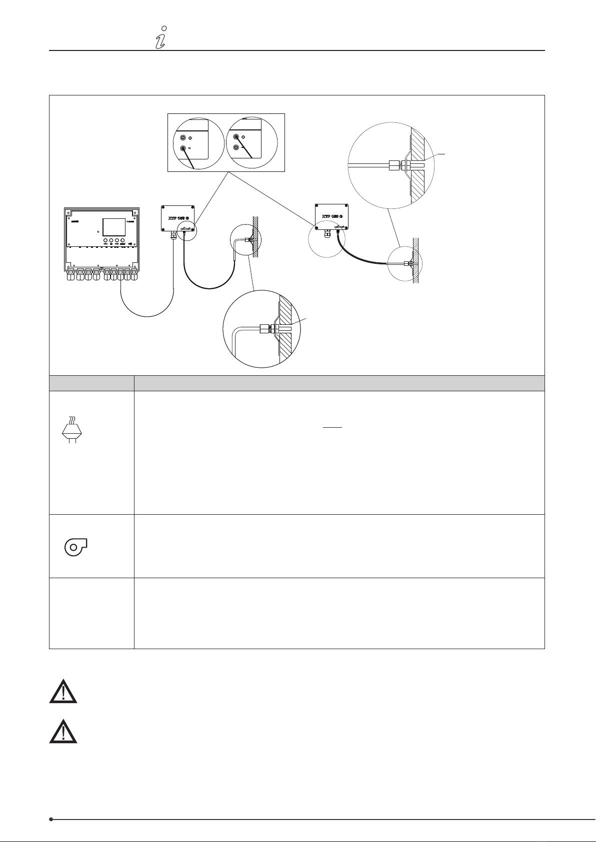
1.3 Fitting. . . . . . . . . . . . . . . . . . . . . . . . . . . . . . . . . . . . . . . . . . . . . . . . . . . . . . . . . . . . . . . . . . . . . .5
1.3.1 Cable length ...............................................................................................5
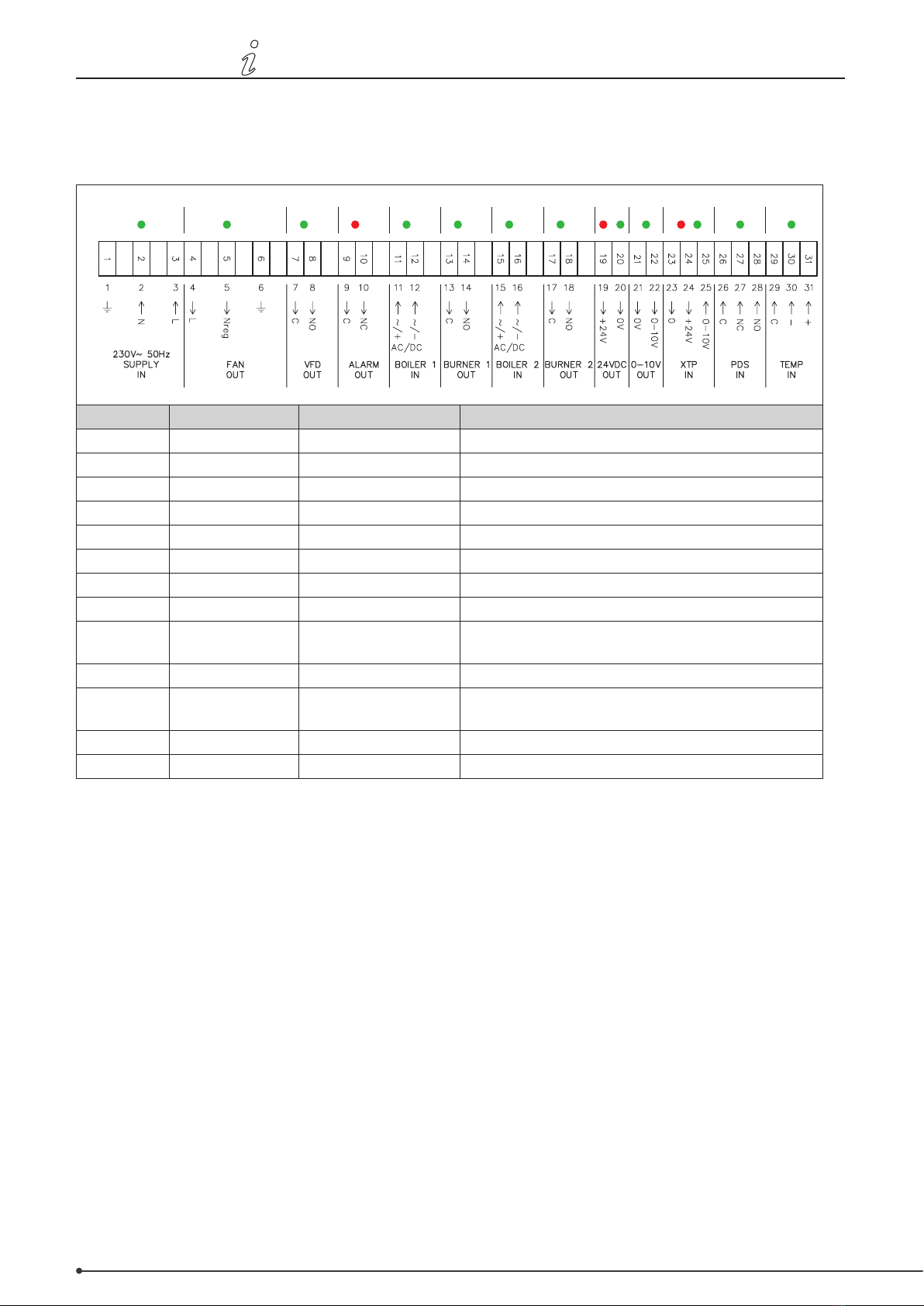
1.3.2 Connection diagram .......................................................................................6
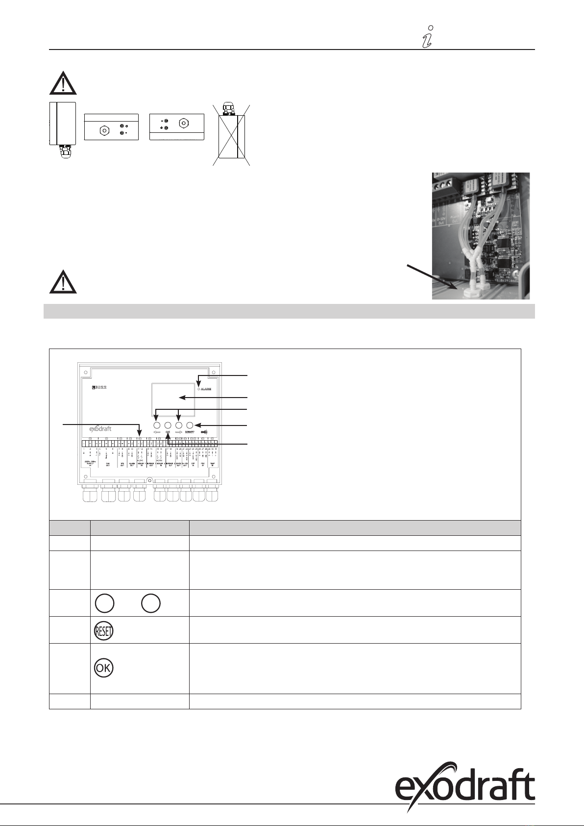
1.4 Layout of the user interface . . . . . . . . . . . . . . . . . . . . . . . . . . . . . . . . . . . . . . . . . . . . . . . . . . . . . . . . 7
1.4.1 Panel ......................................................................................................7
1.4.2 Light emitting diodes and terminal board...................................................................8
1.4.3 Display ....................................................................................................9
1.5 Introduction to the user interface . . . . . . . . . . . . . . . . . . . . . . . . . . . . . . . . . . . . . . . . . . . . . . . . . . . 10
1.6 Set-up. . . . . . . . . . . . . . . . . . . . . . . . . . . . . . . . . . . . . . . . . . . . . . . . . . . . . . . . . . . . . . . . . . . . . 10
1.6.1 Setting the chimney draft ................................................................................ 10
1.7 Service menu . . . . . . . . . . . . . . . . . . . . . . . . . . . . . . . . . . . . . . . . . . . . . . . . . . . . . . . . . . . . . . . . 11
1.7.1 Overview of the service menu ............................................................................ 12
1.7.2 Changing between the operating functions ( - - ) ........................................... 14
2. Pressure-controlled regulation of the chimney fan ................................................15
2.1 Use . . . . . . . . . . . . . . . . . . . . . . . . . . . . . . . . . . . . . . . . . . . . . . . . . . . . . . . . . . . . . . . . . . . . . . 15
2.2 Method of operation . . . . . . . . . . . . . . . . . . . . . . . . . . . . . . . . . . . . . . . . . . . . . . . . . . . . . . . . . . . 15
2.3 Electrical connection . . . . . . . . . . . . . . . . . . . . . . . . . . . . . . . . . . . . . . . . . . . . . . . . . . . . . . . . . . . 15
2.4 Sample wiring diagrams . . . . . . . . . . . . . . . . . . . . . . . . . . . . . . . . . . . . . . . . . . . . . . . . . . . . . . . . . 16
2.4.1 Single- or two boiler application .......................................................................... 17
2.4.2 Single boiler application with potential free contact in boiler .............................................. 18
2.4.3 2 boiler application with continuous operation of chimney fan ............................................ 19
2.4.4 Solid fuel boiler with temperature sensor ................................................................. 20
2.5 User menu. . . . . . . . . . . . . . . . . . . . . . . . . . . . . . . . . . . . . . . . . . . . . . . . . . . . . . . . . . . . . . . . . .21
2.5.1 Layout of the user menu.................................................................................. 21
2.5.2 Operating the user menu................................................................................. 21
2.6 Set-up. . . . . . . . . . . . . . . . . . . . . . . . . . . . . . . . . . . . . . . . . . . . . . . . . . . . . . . . . . . . . . . . . . . . . 21
2.7 Commissioning. . . . . . . . . . . . . . . . . . . . . . . . . . . . . . . . . . . . . . . . . . . . . . . . . . . . . . . . . . . . . . . 22
3. 2-stage speed regulation of exodraft chimney fan ................................................23
3.1 Use . . . . . . . . . . . . . . . . . . . . . . . . . . . . . . . . . . . . . . . . . . . . . . . . . . . . . . . . . . . . . . . . . . . . . . 23
3.2 Method of operation . . . . . . . . . . . . . . . . . . . . . . . . . . . . . . . . . . . . . . . . . . . . . . . . . . . . . . . . . . . 23
3.3 Electrical connection . . . . . . . . . . . . . . . . . . . . . . . . . . . . . . . . . . . . . . . . . . . . . . . . . . . . . . . . . . . 23
3.4 Sample wiring diagrams . . . . . . . . . . . . . . . . . . . . . . . . . . . . . . . . . . . . . . . . . . . . . . . . . . . . . . . . . 23
3.4.1 1 x 2-stage boiler......................................................................................... 24
3.4.2 2 x 1-stage boilers........................................................................................ 25
3.5 User menu. . . . . . . . . . . . . . . . . . . . . . . . . . . . . . . . . . . . . . . . . . . . . . . . . . . . . . . . . . . . . . . . . . 26
3.5.1 Layout of the user menu.................................................................................. 26
3.5.2 Operating the user menu................................................................................. 26
3.6 Set-up. . . . . . . . . . . . . . . . . . . . . . . . . . . . . . . . . . . . . . . . . . . . . . . . . . . . . . . . . . . . . . . . . . . . . 27
3.6.1 Setting the chimney fan output........................................................................... 27
3.7 Commissioning. . . . . . . . . . . . . . . . . . . . . . . . . . . . . . . . . . . . . . . . . . . . . . . . . . . . . . . . . . . . . . . 28
4. Pressure-controlled regulation of exodraft supply air fan .........................................29
4.1 Use . . . . . . . . . . . . . . . . . . . . . . . . . . . . . . . . . . . . . . . . . . . . . . . . . . . . . . . . . . . . . . . . . . . . . . 29
4.2 Method of operation . . . . . . . . . . . . . . . . . . . . . . . . . . . . . . . . . . . . . . . . . . . . . . . . . . . . . . . . . . . 29
4.3 Electrical connection . . . . . . . . . . . . . . . . . . . . . . . . . . . . . . . . . . . . . . . . . . . . . . . . . . . . . . . . . . . 29
4.4 Sample wiring diagram. . . . . . . . . . . . . . . . . . . . . . . . . . . . . . . . . . . . . . . . . . . . . . . . . . . . . . . . . . 29
4.4.1 Connection of frequency converter/MPR relay ............................................................ 30
4.5 User menu. . . . . . . . . . . . . . . . . . . . . . . . . . . . . . . . . . . . . . . . . . . . . . . . . . . . . . . . . . . . . . . . . . 31
4.5.1 Operating the user menu................................................................................. 31
4.6 Set-up. . . . . . . . . . . . . . . . . . . . . . . . . . . . . . . . . . . . . . . . . . . . . . . . . . . . . . . . . . . . . . . . . . . . . 32
4.7 Commissioning. . . . . . . . . . . . . . . . . . . . . . . . . . . . . . . . . . . . . . . . . . . . . . . . . . . . . . . . . . . . . . . 32
5. List of alarms and troubleshooting...............................................................33
5.1 Alarm handling. . . . . . . . . . . . . . . . . . . . . . . . . . . . . . . . . . . . . . . . . . . . . . . . . . . . . . . . . . . . . . . 33
5.1.1 Resetting a current alarm................................................................................. 33
5.1.2 Resetting the alarm log................................................................................... 33
5.1.3 Alarm overview .......................................................................................... 33
5.2 More troubleshooting . . . . . . . . . . . . . . . . . . . . . . . . . . . . . . . . . . . . . . . . . . . . . . . . . . . . . . . . . . 35
5.2.1 Program running......................................................................................... 35
5.2.2 Communication error .................................................................................... 35
6. Technical specications .........................................................................36
7. EU declaration of conformity ....................................................................37

3110009 EBC22 UK 180615 3
Symbol Legend: The following terms are used throughout this manual to bring attention to the presence of
potential hazards or to important information concerning the product.
Prohibition symbol: Failure to observe instructions marked with a prohibition symbol may result i serious
injury or death.
Danger symbol: Failure to observe instructions marked with a danger symbol may result in personal
injury and/or damage to the unit.
TO REDUCE THE RISK OF FIRE, ELECTRICAL SHOCK OR INJURY TO
PERSONS, OBSERVE THE FOLLOWING:
• Use this unit in the manner intended by the manufacturer. If you have questions, contact the supplier at
the address or telephone number listed on the back of the manual.
• Before servicing or cleaning the unit, switch o at service panel and lock service panel to prevent power
from being switched on accidentally.
• Installation work and electrical wiring must be done by a qualied person(s) in
accordance with applicable codes and standards.
• Follow the appliance manufacturer’s guidelines and safety
• standards and the local code authorities
• This unit must be grounded.
No special requirements. Disposal should be carried out in accordance with
statutory regulations related to the disposal of electronic waste.

3110009 EBC22 UK 180615
1. Product information
Description
The EBC22 (exodraft Boiler Control) is a specially designed control component for constant pressure regulation of
chimney draft. EBC is specially designed to comply with the Gas Application Directive.
By changing the operating mode, the EBC22 can also:
• Act as a 2-stage speed regulator (see section 3)
• Control the supply of fresh air to the boiler room (see section 4)
• Automatically start/stop via a temperature sensor in the chimney duct
Layout of the instructions
The EBC22 can control an exodraft chimney fan or an exodraft supply air fan.
There are seven sections to the instructions:
• Read section 1. ”Product information”
• Read the section that deals with the required control methods:
Section 2: Pressure-controlled regulation of exodraft fans (factory-set)
Section 3: Two-step speed regulation of exodraft fans
Section 4: Pressure-controlled regulation of exodraft supply air fan
• Read sections 5–7.
Section 2,3, and 4 deal with the following:
Section 2:
• Pressure-controlled regulation of exodraft chimney fans (default).
• The EBC22 ensures and monitors constant pressure in a chimney.
• The EBC22 is designed for use with boiler systems with 1- and 2-stage burners.
• The EBC22 can also be used for boiler systems with modulating burners.
• The control system monitors chimney draft and shuts down the burner in the event of errors (the alarm-
diode on the EBC22 will turn on).
• The control system is intended for both solid fuel boilers, atmospheric gas boilers, condens and forced
draft boilers for oil and gas.
• The EBC22 can control a chimney fan directly or indirectly via a frequency converter.
Section 3:
• 2-stage speed regulation of exodraft chimney fans.
• The EBC22 can be used as a 2-stage speed regulator for exodraft chimney fans.
• The EBC22 monitors chimney draft and shuts down the burner in the event of errors (the alarmdiode on
the EBC22 will turn on).
• The control system is intended for 1- or 2-stage atmospheric gas boilers.
• The EBC22 can control a chimney fan directly or indirectly via a frequency converter.
Section 4:
• Pressure-controlled regulation of exodraft supply air fans.
• The EBC22 can be used to control an exodraft BESB or BESF box fan.
• The EBC22 ensures and monitors constant pressure in a boiler room.
• The control system monitors the pressure in the boiler room and shuts down the burner in the event of
errors (the alarmdiode on the EBC22 will turn on).
• The EBC22 can control a supply air fan directly or indirectly via a frequency converter.
4 • Product information4 • Product information

3110009 EBC22 UK 180615
1.1 Delivery
The EBC22 is delivered with the following:
Pos. Part Item no. Function
A EBC22 EBC22EU01 Controls exodraft fans and chimney fans. For indoor installations.
EBC22EU02 Controls exodraft fans and chimney fans. For outdoor installations.
B Pressure
transducer (XTP)
XTP150G Measures dierence air pressure in the boiler room or chimney, or
outdoor atmospheric pressure.
C Measuring probe
for EBC22EU01
3200814 Measures pressure in the chimney. (EBC22EU01)
D Measuring probe
for EBC22EU02
3200484 Measures pressure in the chimney. (EBC22EU02)
E 2 m silicone hose 2000335 Supplies the pressure transducer (XTP) with reference pressure from
the measuring probe or from outdoors.
Instructions 3110009 Instructions for tting, installation and operation.
1.2 Accessories
Part Item no. Function
Temperature
sensor
1100755 Measures the temperature
Relay box ES12 If more than 2 boilers are connected
1.3 Fitting
1.3.1 Cable length
Max. cable length between EBC22 and XTP: 100 m.
Max. cable length between EBC22 and chimney fan / fan: 100 m
A
C
B
E
D
Product information • 5Product information • 5

3110009 EBC22 UK 180615
1.3.2 Connection diagram
The EBC22 is to be tted and connected as shown in the diagram below.
Ø5.5
A
A
Ø 5.5
B
A
A
B
B
12
Control of … Fitting procedure
Chimney fan
Remark!
• Fit the EBC22 and the pressure transducer (XTP) in the boiler room.
• Fit the measuring probe(A) in the boiler ue or in the manifold. However, for atmospheric boi-
lers, the probe must always be positioned after the draft hood.
• Connect the hose from the measuring probe to the negative terminal on the pressure transdu-
cer (B”1”).
• When the measuring probe is placed outside it must be mounted in a way that prevents con-
dence or ice to be formed. EBC22EU02 is delivered with a straight measuring probe. If neces-
sary the probe delivered with EBC20EU01 can be straigtened and placed so the condens can
run out.
• EBC20 must always be mounted in a way that protects it from the weather (Rain, snow etc.).
Supply air fan • Fit the EBC22 and pressure transducer (XTP) in the boiler room.
• Connect the hose for measuring reference pressure (outdoor atmospheric pressure) to the
negative terminal (B”1”) on the pressure transducer. Run the hose outside the building to a
place that is not aected by wind, rain, etc. If appropriate, t the free end of the hose in a box
as described at the top of the next page.
Note • Special aspects if you require positive pressure* in the chimney/boiler room:
• Connect the hose to the positive terminal on the pressure transducer (B”2”)
• In menu 16 (see page 12) set the value to 2 (positive pressure). For operation of the service
menu, see page 11
• Please note that the EBC22 is supplied with only 2 m of hose.
NB!
*The default setting of the EBC22 is for negative pressure regulation, but local authority
requirements may state that positive pressure must be maintained.
The pressure transducer cannot be mounted inside an air tight enclosure. It uses the
atmospheric pressure as reference pressure.
6 • Product information6 • Product information

3110009 EBC22 UK 180615
Make sure to position the pressure transducer the right way up.
Outdoor tting of the pressure transducer (XTP)
A
If there is a risk of adverse eect from strong winds, the hose (A) located inside the
XTP 150G can be removed from the (+) valve.
If the pressure transducer is positioned in a place where insects have access to the
free end, tting a sinter lter is recommended.
Do not blow into the valves on the XTP 150 G
1.4 Layout of the user interface
1.4.1 Panel
A
B
C
D
E
F
Pos. Part Function
A Alarm • indicates alarms
B Display • displays operation and changes in the user interface (menu system)
• indicates alarms
• shows normal operation status
C
and
• forward or back in the menu system
• increase/reduce set point
D • reset alarm
• return to operation screen
E • select menu item
• conrm/save change of set point (must be conrmed with OK (the current
set point blinks rapidly) and is saved using OK within 5 seconds (or the set-
ting will not be saved)
F Light emitting diodes • shows status of inputs and outputs
Product information • 7Product information • 7

3110009 EBC22 UK 180615
1.4.2 Light emitting diodes and terminal board
The chart below lists the connection options for the terminal boards and explains the various colours of the light
emitting diodes.
No. Designation Max. load Meaning when the light diode is …
1, 2 & 3 SUPPLY IN 230-240 V AC +/- 10 % green: the EBC22 is connected to a power supply
4, 5 & 6 FAN OUT 3 A green: the triac output is active
7 & 8 VFD OUT 250 V AC, 8 A, AC 3 green: the relay is connected
9 & 10 ALARM OUT 250 V AC, 8 A, AC 3 red: the relay is open
11 & 12 BOILER 1 IN 18 - 230 V DC / V AC green: the input is active
13 & 14 BURNER 1 OUT 250 VAC, 4 A, A C 3 green: the relay is connected
15 & 16 BOILER 2 IN 18 V DC/230 V AC green: the input is active
17 & 18 BURNER 2 OUT 250 V AC, 4 A, AC 3 green: the relay is connected
19 & 20 24 VDC OUT 100 mA green: power supply OK
red: overload
21 & 22 0 - 10 V OUT* 20 mA green: the output is active
23, 24 & 25 XTP IN green: XTP connected
red: return voltage >12 V DC
26, 27 & 28 PDS IN ** green: C & NO are connected
29, 30 & 31 TEMP IN green: temperature sensor connected
* Cable length between 0-10 V output (terminal 21 & 22) must not exceed 100 m and must be of a shielded cable
3 x 0,75 mm2.
** Terminals 26, 27 & 28 can however also be used for connecting other auxiliary surveillance equipment.
8 • Product information8 • Product information

3110009 EBC22 UK 180615
1.4.3 Display
The diagram below shows the layout of the display on the EBC22. All possible display values are stated:
1 2 3 54 6 7 8
10
17
12
15
11
16
13
14
9
Pos. Shows …
1 Symbol indicating the connection of Z-wave
2 Symbol for service menu
3 Symbol for alarms. Displayed in the event of an alarm, along with the illumination of the alarm
diode.
4 Symbol for the operational settings of the service menu (see section 1.6) and the alarm log.
5 Symbol for overheating
6 Symbol for 2-stage speed regulation of exodraft chimney fan
7 Symbol for pressure-controlled regulation of exodraft chimney fan
8 Symbol for pressure-controlled regulation of exodraft supply air fan
9 Symbol indicating:
• PDS error
• PDS check (ashing)
10 • Operation screen: current pressure
• Menu screen: current menu
11 Units
12 Units
13 Menu screen (“VALUE”and, in some cases, “SETPOINT”displayed): Setpoint for the menu item in
question
14 Temperature symbol, indicates:
• Operation screen: current temperature
• Menu screen: temperature parameter setting
15 Timer indicator
16 Pressure symbol indicating that:
• Operation screen: Pos. 10 is displaying pressure
• Menu screen: You are currently altering a pressure parameter
17 Symbol for commissioning
Product information • 9Product information • 9

3110009 EBC22 UK 180615
1.5 Introduction to the user interface
Display
The purpose of the display (see previous page) is to present:
• Operating information (pressure, etc.)
• Alarms
• Setpoints
• Parameters
Menu structure
The menu system in the EBC22 contains:
• User menu (for operation by daily users).
• Service menu (for operation by qualied technical sta).
Layout of the user interface
The user interface is operated through four buttons with the following functions:
Button Function
• Activate the user menu
• Edit and save settings
• Activate service menu (press and hold for 3 seconds)
and
• Go to menu item, and adjust value
• Return to operation screen from any point in the menu system
• Reset alarm when manual reset is selected in menu 25, see page 12
1.6 Set-up
1.6.1 Setting the chimney draft
To set the pressure in the chimney, follow the procedure detailed below
Step. Action... The display shows...
1• Start the heating system.
• The EBC22 displays the actual pressure (in this
example 30 Pa).
2
• Briey press to enter the user menu.
3
• Press
• Press
and
until the required pressure ap-
pears in the lower display.
10 • Product information10 • Product information

3110009 EBC22 UK 180615
4
• Press to conrm the setting (the display blinks
faster)
5
• Within 5 seconds, press again, to save the set
pressure (35 Pa in this example).
6To nish and return to the operation screen, press .
NB
This procedure only applies to setting up the chimney draft.
If you wish to:
• Set the EBC22 up for 2-stage speed regulation of a chimney fan, see page 23
• Set the EBC22 up for pressure control of a supply air fan, see page 29
1.7 Service menu
The service menu is only to be operated by qualied sta.
For an overview of the service menu, see page 12 - 13
Operation of the user menus is described in sections 2, 3 and 4.
Navigation in the service menu
• To activate the service menu, press and hold for 3 seconds
The service menu
operation settings
Service menu
Operation is carried out using the buttons as described above.
• The upper display (pos. 10 on page 9) presents the number of the menu, with the set point for this
menu being shown in the lower display (pos. 13 on page 9).
• Menus whose last digit is“0”are exit menus. These are used to navigate one level back. To do so, press
• To activate the editing options for a menu item, press . The set point will start ashing.
• Conrm selection with .
• Save by pressing again within 5 seconds.
• To exit the service menu, press . This will take you back to the operation screen. Alternatively, you can
navigate back one level at a time if you wish to set multiple menu items.
For examples of how to use the service menu, see 1.7.2 on page 14
Product information • 11Product information • 11

3110009 EBC22 UK 180615
1.7.1 Overview of the service menu
The service menu is built up in four levels:
Base settings for the
three applications
Menu level 1 Menu level 2 Menu level 3 Function Default
0Exit
Service menu
Return to operation screen
1Operation
settings 10 Exit operation settings
11 Operating mode Setting of control/operating function
1 = Pressure-controlled regulation
2 = 2-stage speed regulation
3 = Supply air regulation
1
12 °C / °F Select measuring unit for temperature
1 = °C, 2 = °F 1 (°C) 1 (°C) 1 (°C)
13 Pa / inWC Measuring unit for pressure:
1 = Pa, 2 = inWC 1 (Pa) 1 (Pa) 1 (Pa)
14 Software versions 140 Exit
141 Controller version View Controller software version x.xx x.xx x.xx
142 Safety version View Safety software version x.xx x.xx x.xx
143 Display version View Display software version x.xx x.xx x.xx
15 Select XTP measurement
range 150 Exit
151 Set Low XTP value from -500 Pa to 0 Pa 0 Pa N/A 0 Pa
152 Set High XTP value from 0 Pa to 500 Pa 150 Pa N/A 150
Pa
16 Positive/negative pressure 1 = negative pressure
2 = positive pressure 1 N/A 1
17 OEM functions 170 Exit
171 Cooker function Switch Cooker function ON and OFF N/A OFF N/A
18 Reset to defaults Reset to defaults. If you select“YES”, a
10-second countdown will start, during
which you can cancel your choice by
pressing any button.
NO NO NO
2Alarm 20 Exit Alarm
21 Alarm Log 210 Exit
211-219 The 9 most recent alarms
22 Reset alarm log Resets alarm log NO NO NO
23 Flow Alarm limit Set Flow Alarm limit in %:
: 50-80% ( Alarm when pressure is below xx% )
: 100-300% ( Alarm when pressure is above xx% )
64% N/A 300%
24 Flow Alarm delay Set Flow Alarm delay, 10–60 s 15 s 15 s 15 s
25 Reset auto / manual 1 = automatic, 2 = manual 1
Auto)
1
(Auto)
11
(Auto)
12 • Product information12 • Product information

3110009 EBC22 UK 180615
Base settings for the
three applications
Menu level 1 Menu level 2 Menu level 3 Function Default
3Conguration 30 Exit settings
31 PDS/AUX cong 1 = PDS, 2 = C-NO 2 (C-NO) 1 (PDS)
(Locked)
2(C-NO)
32 Triac settings 320 Exit
321 Umin Min. output voltage in % of 230V AC, 35-100% 35% N/A 35%
322 Umax Max. output voltage in % of 230V AC,35-100% 100% N/A 100%
33 0–10V settings 330 Exit
331 Umin Min. output voltage in % of 10V DC, 0-100% 0% N/A 0%
332 Umax Max. output voltage in % of 10V DC, 0-100% 100% N/A 100%
34 Manual Fan mode 340 Exit
341 Manual Fan mode
on/o
Switch Manual Fan mode on and o OFF OFF OFF
342 Manual Fan mode
speed
Set the motor manually, 35–100% 35% 35% 35%
35 Regulation parameters 350 Exit
351 Amplication Xp Set proportional amplication, 0.2 to 5 2,2 N/A 1,2
352 Integration time Ti Set integration time from 1 to 30 s 5 N/A 3
353 Dierential time Td Set dierential time from 1 to 30 s 1 N/A 5
354 Sample time Set sample time from 1 to 999 ms 300 ms N/A 300 ms
4Temp. sensor 40 Exit Temp. sensor
41 Sensor ON/OFF turn temperature sensor ON/OFF OFF OFF
42 Auto Start/Stop 420 Exit
421 ON/OFF turn temperature sensor ON/OFF OFF OFF
422 Start temperature select start temperature in 5–450 °C range 40 °C 40 °C
423 Stop temperature select stop temperature in 0–445 °C range 35 °C 35 °C
43 Forced operation 430 Exit
431 ON/OFF turn forced operation ON/OFF OFF OFF
432 Limit temperature select temperature limit in 5–450 °C range 250 °C 50 °C
44 Alarm 440 Exit
441 ON/OFF turn alarm ON/OFF OFF OFF
442 Limit temperature select temperature limit in 25–450 °C range 450 °C 450
°C
443 Alarm delay Select delay-length of limit temperature
alarm: 0–60 second range 5 5
Important: Menu 4 must only be used for solid fuel!
Product information • 13Product information • 13

3110009 EBC22 UK 180615
1.7.2 Changing between the operating functions ( - - )
Default operating function
As its base function, the EBC22 is factory set to pressure-controlled regulation of exodraft chimney fans
(operating function 1 )
How to change the operating function
Step Action... The display shows...
1
• Press and hold for 3 seconds
2
• Press
to go to menu 1.
• Press to go to menu 10.
3
• Press
to go to menu 11
• Press
4
Press
until the symbol and number for the operating function you
require is displayed. The three operating functions are:
1 Pressure-controlled regulation of exodraft chimney fans
(default)
2 2-stage speed regulation of exodraft chimney fans
3 Pressure-controlled regulation of exodraft supply air fan
symbol is changed
5
• Press to conrm selection (the display blinks faster)
6
• Within 5 seconds, press again, to save selection.
(display stops blinking).
7 • To nish and return to the operation screen,
press
14 • Product information14 • Product information

3110009 EBC22 UK 180615
2. Pressure-controlled regulation of the chimney fan
2.1 Use
Area of use
• The EBC22 is designed for use with boiler systems with 1- and 2-stage burners.
• The EBC22 can also be used for boiler systems with modulating burners.
• The EBC22 can also be used for multiple boiler systems
• The control system is intended for:
solid fuel boilers,
atmospheric gas boilers
forced draft boilers for oil and gas
condensing boilers.
• The EBC22 can control a chimney fan directly or indirectly via a frequency converter.
2.2 Method of operation
General function
• The control system monitors chimney draft and disconnects the burner in the event of errors (the alarm-
diode on the EBC22 will turn on).
• When the boiler thermostat demands heat, the chimney fan will start at max. voltage, the burner start is
delayed
• When the EBC22 registers sucient chimney draft, the burner is released.
• The EBC22 maintains the set pressure by regulating the voltage. The pressure is shown in the display.
• In the event of an insucient pressure the burner will be disconnected after 15 seconds.“Insucient pres-
sure”is less than 64% of the set value, corresponding less than 80% ow.
• When the boiler switches o, the chimney fan is also stopped. However, it is possible to set a post-purge
period for the chimney fan (see page 21). Alternatively, the control system can be set up to keep the
chimney fan running continuously (see page 19).
Light emitting diodes and output signals
All inputs and outputs are linked to light emitting diodes for the monitoring and service of the system (1.4.2 Light
emitting diodes and terminal board, page 8 ).
The EBC22 has 0–10V output signals for controlling multiple chimney fans via frequency converters or motor power
relays.
2.3 Electrical connection
This work must be performed by a qualied electrical engineer, in accordance with locally applicable rules and
legislation.
The installation of the supply cable must be carried out in accordance with applicable regulations and
legislation.
The earth terminal ( ) must always be connected.
When connecting pressure transducer (XTP) and frequency converter, screened cable must be used.
Isolation switch
exodraft stresses that according to EU’s Machinery Directive an isolation switch must be set up in the xed
installation.
The isolation switch is not supplied by exodraft. Available as an extra.
Pressure control • 15

3110009 EBC22 UK 180615
2.4 Sample wiring diagrams
As a constant pressure regulator for exodraft chimney fans, the EBC22 can be connected to a range of dierent signals.
The following pages are sample wiring diagrams, and show the following:
• 2.4.1 Single- or two boiler application, page 17
• 2.4.2 Single boiler application with potential free contact in boiler, page 18
• 2.4.3 2 boiler application with continuous operation of chimney fan, page 19
• 2.4.4 Solid fuel boiler with temperature sensor, page 20
Contact the boiler manufacturer for details of correct connection of the boiler control system.
16 • Pressure control

3110009 EBC22 UK 180615
2.4.1 Single- or two boiler application
This example shows how to connect a voltage signal (10–230V AC/DC) for the EBC22 to start/stop the fan from one or
two independent boilers:
• Connect the supply voltage to terminals 1–3
• Connecting the boilers:
Connect the burner start signal (L) to terminal 11 & 15
Connect the neutral wire to terminal 12 & 16
The start signal for the burner is sent from terminal 14 & 18
• Loop terminals 11 and 13
• Loop terminals 15 and 17
• Connect the chimney fan to terminals 4–6
• Connect the pressure transducer (XTP) to terminals 23–28
Pressure control • 17

3110009 EBC22 UK 180615
2.4.2 Single boiler application with potential free contact in boiler
This example shows how to connect a potential free contact to the EBC22 to start/stop the fan:
• Connect the supply voltage to terminals 1–3.
Connection to the boiler:
Connect the potential free contact to terminals 11 & 19.
Loop terminals 12 & 20.
• Connect the burner start signal to terminals 13 & 14.
• Connect the chimney fan to terminals 4–6.
• Connect the pressure transducer (XTP) to terminals 23–28.
18 • Pressure control

3110009 EBC22 UK 180615
2.4.3 2 boiler application with continuous operation of chimney fan
This example shows how to connect the EBC22 if you require continuous operation of the chimney fan from one or two
boilers:
• Connect the supply voltage to terminals 1–3.
• Loop terminals 11 & 19.
• Loop terminals 12 & 20.
• Connection to boiler (example with 2 boilers):
Connect the boiler 1 start signal to terminals 13 & 14.
Connect the boiler 2 start signal to terminals 17 & 18.
• Connect the chimney fan to terminals 4–6.
• Connect the pressure transducer (XTP) to terminals 23–28.
Pressure control • 19

3110009 EBC22 UK 180615
2.4.4 Solid fuel boiler with temperature sensor
Showing how a fan is started and stoped via a temperature sensor in the ue duct.
Example showing how a fan start/stop temperature sensor is connected to the EBC22.
• Connect the supply voltage to terminals 1–3
• Connecting the boiler:
Connect the burner start signal (L) to terminal 11.
Connect the neutral wire to terminal 12.
Loop terminals 11 and 13.
The start signal for the burner is sent from terminal 14
• Connect the fan to terminals 4-6.
• Connect the pressure transducer (XTP) to terminals 23–28.
• Connect the temperature sensor through a junction box to terminals 29-31
20 • Pressure control
Other manuals for EBC22
1
Table of contents
Other Exodraft Control Unit manuals
Popular Control Unit manuals by other brands

Fluidmaster
Fluidmaster PerforMAX 400AH Quick install guide

Texas Instruments
Texas Instruments OPT3004EVM user guide

Rabbit
Rabbit RabbitCore RCM3000 user manual

Boardcon Embedded Design
Boardcon Embedded Design CM3588S Reference User Manual

GEM
GEM R487 Victoria operating instructions

Tektronix
Tektronix 73A-851 user manual