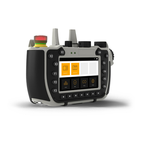
Exor SceneSelect II SRC420 User manual

Warning ............................................................. 2
Features ............................................................ 2
Important Safeguards ........................................ 2
Electrical Diagram .............................................. 3
Installation Steps................................................. 3
Connecting Serial Control Cables....................... 4
Product Specifications ...................................... 4
Contents
Ex-Or
Haydock Lane, Haydock, Merseyside WA11 9UJ
Tel: 01942 719229 Fax: 01942 272767 Email: technicalsales.ex-or@ex-or.com
www.ex-or.com
W4380B
SRC420
Instruction Manual
RELAY CONTROLLER
SceneSelect II
Scene-setting and Dimming System

ISOLATE FROM
MAINS SUPPLY BEFORE
REMOVING THIS COVER
NO USER SERVICEABLE PARTS INSIDE
SERVICE BY QUALIFIED PERSONNEL ONLY
WARNING
Warning
TO REDUCE THE RISK OF FIRE OR
ELECTRIC SHOCK, DO NOT EXPOSE
THIS DEVICE TO RAIN OR
MOISTURE.
DO NOT ENERGISE UNLESS THE
FRONT COVER IS IN PLACE.
THIS DEVICE MUST BE EARTHED.
INSTALLATION, PROGRAMMING AND
MAINTENANCE MUST BE CARRIED
OUT BY QUALIFIED PERSONNEL.
2SRC420 Instruction Manual - W4380B
Important Safeguards
Read Instructions We recommend that you
read this Instruction Manual prior to
commencement of installation.
Special Programming This device will only
operate in basic modes unless programmed
via a computer. Should programming be
required, contact Ex-Or for details. Once the
data cable is connected to the device(s), the
factory default settings will allow any control
panel to control all channels in all dimmers.
Check Connections
Tighten all load-carrying screw connections as
vibrations from transport can cause terminal
block screws to become loose.
Power Sources This device should only be
operated from the type of supply specified on
the front cover. This device must be earthed.
Output Circuits The load should not exceed
the specified of 20A. Loads should be
calculated to ensure that the overall maximum
capacity of 80A is not exceeded. This device
should be fed via an HRC fuse or MCB.
Mounting Location Install in a dry, well-
ventilated location. Controllers may emit
some mechanical noise. Take this into
account when deciding the mounting location.
Data Cable The recommended cable for
connections to the programming socket is
4 pair patch (multi-stranded) CAT5 screened
cable. This cable should be segregated from
mains cables by a minimum distance of
300mm. If expected cable runs are over
600 metres for bus cables or 12 metres for
analogue cables, consult Ex-Or for advice.
Do not cut or terminate live data cables.
Features
1 phase at 0.1A
4 x Feed Through Outputs
Rated at 20A
Manual Overrides for each channel
Temporary overrides for each channel
via switches on front of unit.
Note: These overrides do not provide
permanent isolation.
Dry Contact Interface
Can be programmed to perform many
different functions. The factory
settings will cause this input to
transmit network identification
information.
Many Control Options
Control of this device can be from any
of the SceneSelect II range of control
panels and ancillary products.
Simple Installation
DIN rail mount facilitates installation.
All connection terminals are
accessible without disassembly.
Single Phase Supply

3
Electrical Diagram
Installation Steps
1. Mount the device on a DIN rail inside an approved enclosure.
2. Calculate loads to ensure individual channels are not overloaded, then connect loads to the output
channels. The maximum loading of this device is as follows:
Maximum Channel Load: 20A 230V AC
Total Box Load: 80A
3. Connect a single phase 0.1A feed to the supply terminals. This device must be earthed.
4. Connect SceneSelect Bus cables to the device as per the diagrams overleaf.
5. If the Auxiliary input is to be used, connect a dry contact device in between the AUX and GND terminals.
Keep cable runs between the SRC420 and the dry contacts under two metres. The function of the
Auxiliary input will need to be programmed at the time of commissioning.
SRC420 Instruction Manual - W4380B
P
CH1
CH2
CH3
CH4
SHIELD
D+
GND
D
-
+12V
AUX
RS485
SceneSelect II Bus
IN
IN
IN
IN
OUT
OUT
OUT
OUT
L
N
E
Control
Supply:
230V 0.1A
1 Phase

Recommended Cable Colour Coding
Green/White pair paralleled for GND
Orange/White pair paralleled for +12V
Blue/White pair Blue for DATA+
White for DATA-
The colour coding scheme used is not critical,
as long as the same scheme is used
throughout the installation.
The screen of the data cable must be
connected where there is a terminal
provided.
Recommended Cable Types include:
Belden 1868E
RS Components 628-6805
Farnell 1350507
4
Connecting Serial Control Cables
Product Specifications
Supply: 230V 50Hz single phase at 0.1A
Load Outputs: 4 x Feed Through Outputs @ 20A - Max Box Load 80A
Switching Device: Relay - 50A 230V AC inductive (5000W Lighting Load rated)
2
Supply Terminals: 1 x Phase, 1 x Neutral 1 x Earth (up to 1 x 4mm cable per terminal)
2
Load Terminals: IN / OUT for each channel, up to 1 x 4mm cable per terminal
Control: SceneSelect Bus Network Control
AUX input (function of AUX is programmable via internal sequencer)
SceneSelect Bus DC Supply: 120mA (capacity for approx 5 Control Panels)
Preset Scenes: 170
Compliance: CE, C-Tick
o
Ambient Temperature: 50 C max
Construction: Polycarbonate plastic DIN rail mount
Dimensions: Height 93mm x Width 105mm x Depth 75mm
Weight: 0.324kg
SRC420 Instruction Manual - W4380B
RJ12 Socket Connections
Serial Cable Permanent Connections
INSTALLATION DETAILS
INPUT: 230 V 50-60Hz 10 A
OUTPUT: 1 x 230V 10A
MOUNT VERTICALLY
AGAINST WALL
ENSURE GOOD VENTILATION
FOLLOW INSTALLATION
INSTRUCTIONS
Unit6-119/133 McEVOY St. Alexandria
NSW2015 AUSTRALIA
Manufacturedby:
ISOLATEFROM
MAINSSUPPLYBEFORE
REMOVINGTHISCOVER
NOUSERSERVICEABLE PARTS INSIDE
SERVICEBYQUALIFIED PERSONNEL ONLY
WARNING
Connect Data Cable in a "Daisy Chain"
1 cable
2 cables
2 cables 2 cables
SceneSelect II
SceneSelect II
GND
SHIELD
D+
D
+12V
ORANGE/WHITE PAIR
BLUE/WHITE PAIR
GREEN/WHITE PAIR
SCREEN
(Must be connected if there
is a screen/shield terminal
provided)
Sample
Colours
SPARE
PLUS
DATA --
DATA +
GND
SPARE
Blue
White
Other Exor Controllers manuals