manuals.online logo
Brands
  1. Home
  2. •
  3. Brands
  4. •
  5. Exor
  6. •
  7. Transceiver
  8. •
  9. Exor UBT2000 Installation and operation manual

Exor UBT2000 Installation and operation manual

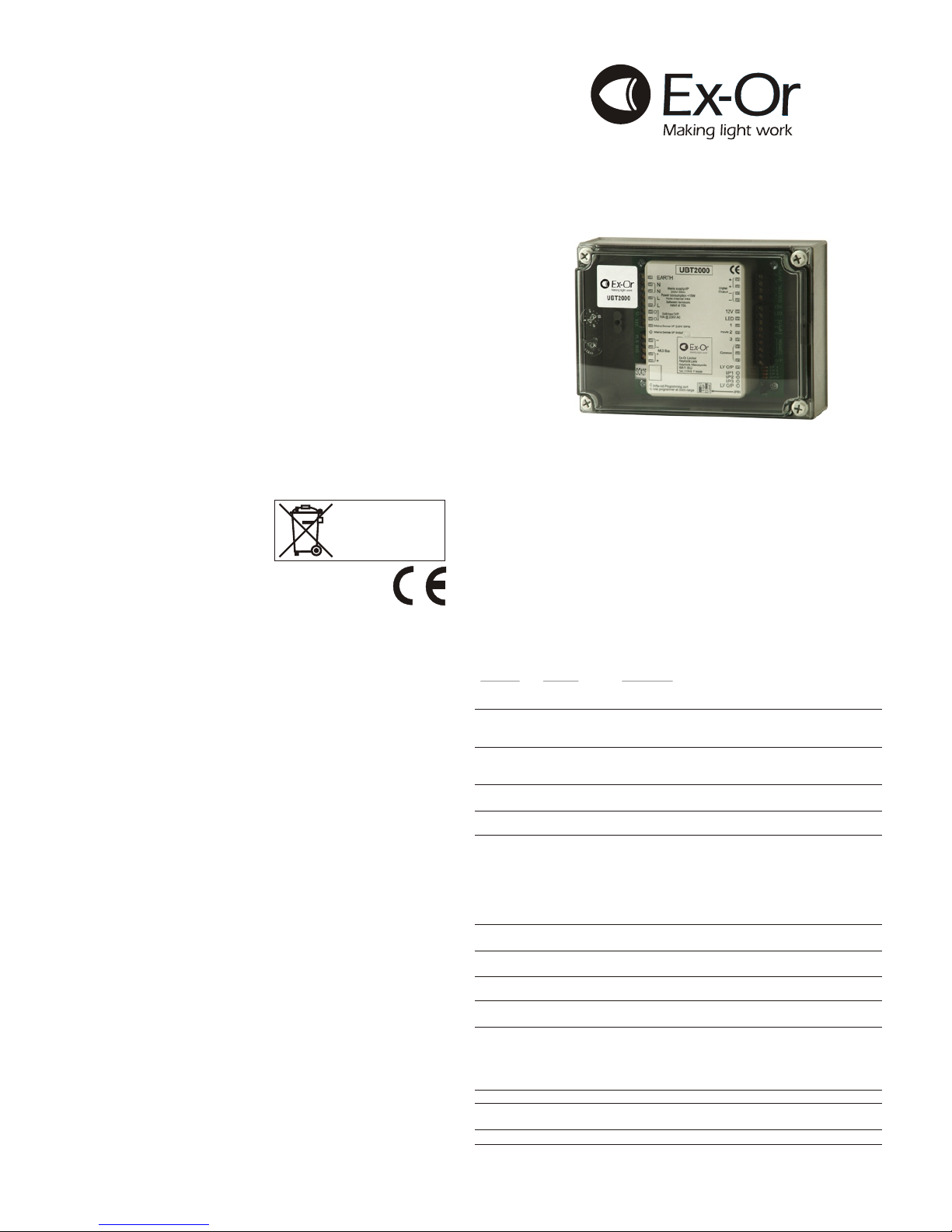
UBT2000 - Digital Universal Bus Transceiver
Only suitably qualified personnel should install this equipment.
The UBT2000 expands the scope of The Ex-Or MLS Digital by enabling otherwise
uncontrolled lighting and non-lighting loads to be brought into the system.
UBTs also allow external devices to provide inputs into the system.
Fixing
The UBT is supplied in a protective housing which should be mounted where it is
accessible for programming purposes. It must not be installed in a position where it
would be exposed to infrared pollution, e.g. in close proximity to fluorescent tubes.
Connection
2
The MLS Bus cable should be 1.5mm twisted pair unscreened.
2
The digital output cable should be 1.5mm 2-core flex unscreened.
22
The mains supply terminals are suitable for 1 x 4mm or 2 x 2.5mm cable.
For connection options please see overleaf; also MLS Wiring Guide AN4001.
Do not connect mains to the MLS bus.
W4078H
Technical Data
2
MLS CABLE: 1.5mm unscreened twisted-pair : see Application Note AN4001
RANGE TO HP2000: 0.2m (8 inches)
OPERATING VOLTAGE: 230V 50Hz (UK & Europe)
PRODUCT RATING & RECOMMENDED CIRCUIT PROTECTION: 10 Amps
MAXIMUM RECOMMENDED LOAD:10 Amps
Incandescent lamps: 1500W max (at 230V)
DIGITAL DIMMING OUTPUT LOAD: up to 20 BALLASTS
POWER CONSUMPTION: <10W
WEIGHT: 112g
SIZE: 175mm x 125mm x 75mm
This device presents a load of 1 unit to the MLS Bus.
Commissioning a UBT using the HP2000
When commissioning a UBT, the HP2000 should be held at a shorter
distance from the unit than for detectors, ie not more than 0.2m away
from the infrared transmitter and receiver which are positioned just
below the MLS bus connections.
1. Switch on HP2000 by pressing the red power button.
2. Point HP2000 at the UBT and press the DOWNLOAD button. The
HP2000 will confirm the product’s identity and call up the correct
menu of parameters and their current settings.
3. Use a combination of UP, DOWN, FORWARD and BACK buttons
to navigate the parameter menu, selecting options for each shown.
(See Tips below.)
4. When options for all parameters have been selected, point the
HP2000 at the UBT and press the UPLOAD button. The
luminaire(s) will switch off briefly during the programming process
and the HP2000 shows DATA OK to confirm operation.
5. After a short period of inactivity (default 5 minutes), the HP2000
hibernates retaining the most recent settings.
Tips
i) Where there are only two options such as ON/OFF, a double click
of the OK button toggles between them.
ii) Where there are multiple options, a double click of the OK button
recalls a list of all options for that parameter. Use the UP, DOWN
and OK buttons to select.
iii) Use the OK button to go forward (through the menus) without
displaying help pages.
iv) Press UPLOAD at any time to transfer all current settings from the
handset to the product.
Please refer to HP2000 instructions for comprehensive commissioning
details.
When commissioning, the following options are available (pre-sets shown in bold):
Function Options Description
Power-up On/Off Sets the digital output and relay state at power-up
irrespective of occupancy.
Response Auto/ Auto: switches on and off automatically.
Semi-auto Semi-auto: requires input commands on inputs 1-3 or the
MLS Bus to switch on but switches off automatically.
Min on-time No/Yes If set to Yes, the luminaires stay on for at least 20 minutes
regardless of the Off delay. Once the Minimum on-time
has elapsed, the programmed Off delay is reinstated.
Off delay 5-60 min Off delays are programmable in 5 minute steps with a
20 min 10 second walk-test option.
Bus connect Yes/No Selecting No electronically disconnects the unit from the
bus.
Zones 1 to 50 Seven zones are listed which can be programmed at the
Pre-set to -- time of commissioning. Detectors programmed to the
(no zone) same zone switch on or stay on when movement is
detected anywhere in that zone. The 5th, 6th and 7th
entries in the list may also be programmed as Common
Zones or Global Zones (see Note 3 overleaf re Global
Messages).
Input 1-3 Various When the switch inputs go active, the programmed
Sustain command is transmitted to the zones in the UBT’s list.
Start lamps Min/Max Selects the digital dimming output at power-up which then
adjusts to the required state.
Entry scene 1-6 Choose scene 1-6 which is selected when the area is first
Scene 1 occupied.
Fade to off No/Yes After the Off delay, digital dimming output either switches
off or fades to off gradually over a few minutes.
Vacant Off Switch off after off delay.
Scn 6 Go to Exit Scene (Scene 6) until next occupancy.
Scn 6 3 hr Go to Exit Scene (Scene 6) for 3 hours then switch off.
Scn 6 bld Go to Exit Scene (Scene 6) until building is vacated then
switch off.
User remote Simulates HC5 functions.
Request Extracts information regarding product type and current
download settings from Ex-Or device.
Programme all Transmits all programme parameters.
Installation and Commissioning
Instructions
Note: HP2000 required for commissioning
(Please read these instructions fully before installation)
UBT2000
Universal Bus Transceiver for use with
The Ex-Or MLS Digital
Ex-Or Limited
Haydock Lane, Haydock,
Merseyside WA11 9UJ
Tel: (01942) 719229
Fax: (01942) 272767
Email: ex-or@ex-or.com
www.ex-or.com
At the end of their useful life
the packaging and product
should be disposed of via a
suitable recycling centre.
Do not dispose of with normal
household waste.
Do not burn.
Important Additional Notes
1. All terminals on this product are provided for final connections. It is not intended that the product
be used as a junction box for looping cables.
2. A means for disconnection must be incorporated in the fixed wiring in accordance with the
current wiring regulations.
12V
LED
LV O/P
I/P1
I/P2
I/P3
LV O/P
1
2
3
Not Used
Not Used
_
_
+
+
Mains Sense I/P 230V 50Hz
Volt-free O/P
10A @ 230V AC
MLS Bus
Inputs
JPR1
Common
Mains Sense I/P Indicator
Infrared Programming port
Use programmer at 20cm range
Edge
Level
Input: MLS Bus signal from other MLS devices programmed to the same zone.
Action: The UBT’s internal timer (for the purpose of operating its relay and digital output)
is started or refreshed.
Closes volt-free output - to operate external device/signal BMS etc.
Sends digital signal to ballasts (if connected) to set light level as programmed.
EARTH
E
N
N
N
N
L
L
L
_
_
+
+
Digital
Output
Mains supply I/P
230V 50Hz
Note: Internal links
between terminals
rated at 10A
UBT2000
USING THE UBT TO RECEIVE SIGNALS FROM THE BUS TO SWITCH
AN EXTERNAL NON-MLS DEVICE (RECEIVER MODE)*
USING THE UBT AS AN INTERFACE DEVICE (TRANSMITTER MODE)*
12V
LED
LV O/P
I/P1
I/P2
I/P3
LV O/P
1
Switch
Input from a non-
MLS device (see
Notes 1 and 2)
This connection
is Not Used
Not Used
Not Used
+ve Switch Indicator LED
(-ve LED Connection to any of 3 Common)
Mains Sense I/P 230V 50Hz
Volt-free O/P
10A @ 230V AC
JPR1
Infrared Programming port
Use programmer at 20cm range
Edge
Level
Input: Signal on input 1, 2 or 3 from an external switch. These inputs
can be programmed to send Global Commands (which will be
received by all devices programmed to accept Global Commands -
see Note 3) as follows:
SUSTAIN - Assume local presence, i.e. stay ON if already ON,
switch ON if OFF, unless switched OFF manually.
OFF - Switch off
SCENE 1-6 - Go to specified scene
ON - Switch on to your entry scene.
PARTITION - Causes any zone information programmed
to the 3rd and 4th positions to be disregarded
temporarily (see Application Note AN4002).
A momentary input will action the command and local presence will
sustain it. A latched input will maintain the command regardless of
presence until the input is opened. If using a latched command, link
JPR1 must be set to ‘Level’.
Action: The UBT’s internal timer (for the purpose of operating its
relay and digital output) is started or refreshed. Sends signal out on
MLS Bus, communicating with similarly programmed devices on the
same zones.
Note 1 Mains Sense Input
230V 50Hz input sends SUSTAIN command, as above, to all other MLS
devices programmed to the same zone and common zones.
Note 2 Phase Connections
Please ensure that all mains-voltage connections are fed from the same
phase as the UBT2000 power supply input.
Note 3 Global Messages
The 5th, 6th and 7th Zones may be programmed as Global Zones and,
as such, will transmit and/or receive Global Messages. Global Messages
add an extra, independent layer of control and can be used for load
shedding, setting a scene for when the building is empty, and many other
applications some of which are illustrated below. There are two Global
Zones that can either Transmit and Receive (G1 and G2 TxRx) or
Receive only (G1 and G2 Rx). Global Zones are set by choosing ‘Yes’
(they are pre-set to No) at the time of commissioning. In this way the UBT
may broadcast information to other system devices (e.g. presence
detectors) that are also programmed to respond to Global Messages.
The UBT can be used in either Transmitter or Receiver mode,
*
or both, for any combination of the features.
EARTH
E
N
N
N
L
L
DSI (or DALI) Output to
Control Luminaires
20 Ballasts max
DSI (or DALI) Output to
Control Luminaires
20 Ballasts max
L
_
_
+
+
Digital
Output
Mains supply I/P
230V 50Hz
Note: Internal links
between terminals
rated at 10A
UBT2000
2
3
MLS Digital Bus
connection
Switch Input Device
_
_
+
+
MLS Bus
Inputs
Common
Mains Sense I/P Indicator
MLS Digital Bus
connection
This connection
is Not Used
See Note 2
See Note 2
MLS Bus
MLS Bus
MLS Bus
MLS Bus
BMS
Output
Standby
Generator
Intruder or
Fire Alarm
Security Office
Keyswitch
230V
230V
230V
UBT2000
UBT2000
UBT2000
UBT2000
Suitable for: Time-switching, e.g. Common Zones
Go to a Scene, e.g. Out-of-hours pattern
Suitable for: Load-shed Global Message (see Note 3)
Suitable for: ALL (or selected) ON Global Message (see Note 3)
Suitable for: ‘Switch On’ Security Patrol Pattern
Examples of Remote Inputs to MLS Digital Examples of Outputs to Remote Device from MLS Digital
MLS Bus
230V
UBT2000
MLS Bus
230V
230V 10A Switched output
(using volt-free contacts) for:
Non-dimming Luminaires
Blinds
Screen
Other devices
Digital output for:
Remote Digital Luminaires
Digital Transformers
UBT2000
W4078H

Other Exor Transceiver manuals

Exor UBT2000DIN Installation and operation manual

Exor

Exor UBT2000DIN Installation and operation manual

Popular Transceiver manuals by other brands

R.L.DRAKE T-4X instruction manual

R.L.DRAKE

R.L.DRAKE T-4X instruction manual

Alinco DJ-V57T instruction manual

Alinco

Alinco DJ-V57T instruction manual

Ltech LT-874 Series manual

Ltech

Ltech LT-874 Series manual

Yaesu FT-8900R Brochure & specs

Yaesu

Yaesu FT-8900R Brochure & specs

Kenwood TR-7400A Service manual

Kenwood

Kenwood TR-7400A Service manual

Kenwood TK-8100-1 instruction manual

Kenwood

Kenwood TK-8100-1 instruction manual

Yaesu FT-8100R Technical supplement

Yaesu

Yaesu FT-8100R Technical supplement

Kenwood TK-2407 instruction manual

Kenwood

Kenwood TK-2407 instruction manual

Ritron RPM-150 Application note

Ritron

Ritron RPM-150 Application note

Kenwood TK-2140 Service manual

Kenwood

Kenwood TK-2140 Service manual

GME CP50 instruction manual

GME

GME CP50 instruction manual

Vertex Standard VX-1210 operating manual

Vertex Standard

Vertex Standard VX-1210 operating manual

Yaesu FT-817ND operating manual

Yaesu

Yaesu FT-817ND operating manual

XIEGU X108 user manual

XIEGU

XIEGU X108 user manual

Yaesu FT-897 Technical supplement

Yaesu

Yaesu FT-897 Technical supplement

Motorola GP360 Series operating instructions

Motorola

Motorola GP360 Series operating instructions

Midland 13-513 owner's guide

Midland

Midland 13-513 owner's guide

Transition Networks E-FRL-MC01A installation guide

Transition Networks

Transition Networks E-FRL-MC01A installation guide

manuals.online logo
manuals.online logoBrands
  • About & Mission
  • Contact us
  • Privacy Policy
  • Terms and Conditions

Copyright 2025 Manuals.Online. All Rights Reserved.