Introduction
Our inverter-charger is Pure Sine-Wave,Low-Frequency, and comes equipped with
an On-board Intelligence System that handles most of the heavy lifting within your
electrical system. The inverter converts 12 volt direct current (VDC) into 110 volt
alternating current (VAC), or more commonly, the power you utilize at home through
your wall outlets. A typical solar power system consists of a solar panel, solar charge
controller, inverter, battery, and intermediary components such as fuses and breakers.
This inverter also has an Auto Transfer Switch also known as the Bypass Feature
which allows the system to be used with or without batteries meaning it can depend
solely on shore-power for all your AC and DC appliances.
Core Advantages:
• Low frequency - Heavy duty transformer
• High conversion efciency (90%〜98%)
• Intelligent CPU management
• Latest inverter technology
• Best electric components
ExpertPower 12V Inverter-Charger
Applications
Pg. 3
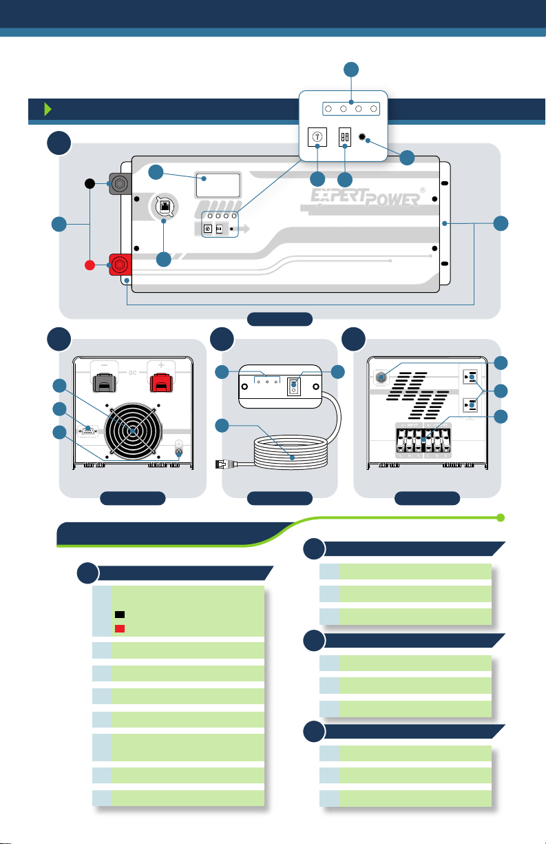
Product Overview
Home Power Tools
Office Equipment
Household Appliances
Kitchen Appliances
Industrial Equipment
Home Entertainment
Circular saws, drills, grinders, sanders, buffers, air
compressors, weed and hedge trimmers.
Computers, phones, monitors, printers, scanners, 3D
printers, fax machines, internet and Wi-Fi modems.
Vacuum cleaners, fans, clippers, electric shavers,
sewing machines, lights, washers and dryers.
Coffee makers, blenders, ice makers, toasters, electric
stoves, dish washers, refrigerators, and water pumps.
Metal halide lamps, high-pressure sodium lamp, air
compressors, and ventilation systems.
Televisions, blue-ray players, gaming consoles, stereos,
musical instruments, and satellite TV receivers.