Expert EX-9132C-2RS485 User manual

EX-9132C-2RS485
Serial to TCP/IP Converter
Version 1.2,14th Nov. 2012

1
Table of Contents
1. Introduction ……………………………………………… 3
Overview ……………………………………………………… 4
Package Checklist ……………………………………………… 4
Block Diagram ………………………………………………… 5
Features ………………………………………………………… 7
Product Specifications ………………………………………… 8
2. EX-9132C-2RS485 Description ....................…………… 10
Product Panel Views …………………………………………… 10
Top Side ………………………………………………………… 10
Right Side ……………………………………………………… 11
Left Side ………………………………………………………… 12
LED Indicators ………………………………………………… 13
Wiring Architecture …………………………………………… 14
RS-232 ………………………………………………………… 14
RS-422/RS-485 ………………………………………………… 14

2
3. EX-9132C-2RS485 Configuration ........................……… 16
Initial IP Configuration ...……………………………………… 16
Device Management Utility of EXBrowser …………………… 16
Menu “View” …………………………………………………… 18
Menu “Config” ………………………………………………… 18
Web Console Configuration ………………………………… 21
Controller Status ……………………………………………… 21
Controller Setup ……………………………………………… 24
Controller Updated …………………………………………… 30
Factory Default Setting ……………………………………… 31
4. Setting Verification …………………………………… 32
Hyper Terminal for TCP/IP WinSock ……………………… 33
Hyper Terminal for COM Port ……………………………… 38
Data Transmission …………………………………………… 39
Appendix A - FAQ ………………………………………… 40
Appendix B - Pin Outs and Cable Wiring ………… 41
B.1 DC-In Jack ……………………………………………… 41
B.2 RJ-45 Pin Assignment …………………………………… 41
B.3 RS-232 Pin Assignment ………………………………… 41
B.4 RS-232 Wiring Diagram ………………………………… 42
B.5 RS-422 Pin Assignment ………………………………… 42
B.6 RS-422 Wiring Diagram ………………………………… 42
B.7 RS-485 Wiring Diagram ………………………………… 42

3
1
1
Introduction
We provide new ways of connecting legacy serial devices to a Local Area Network (LAN)
or Wide Area Network (WAN). TCP/IP converters are designed to operate serial ports
over 100M bps Ethernet networks. The data is transmitted via TCP/IP protocol. Therefore,
control is available via Ethernet, Intranet and Internet. EX-9132C-2RS485 converter is
packaged in a PVC material case well suited for industrial environments. It provides two
serial ports one is a RS-485/422 and another is RS-232/422/485 (Auto-Detect). All serial
ports operate in common industrial configuration.
EX-9132C-2RS485 converter is a low-cost, high performance design. By carefully
selecting high quality with competitive prices components in the world, the products
made network connectivity possible with affordable cost for virtually all kinds of devices.
EX-9132C-2RS485 is a full set converter device with two serial ports as one is a
RS-485/422 port and another is a RS-232/422/485 (Auto-Detect) and it provides one
socket connection port. This operation manual will guide you step by step to learn the
various functions of the EX-9132C-2RS485 converter.
The following topics are covered in this chapter:
□
□
□ Overview
□
□
□ Block Diagram
□
□
□ Product Features
□
□
□ Product Specifications
Overview
EX-9132C-2RS485 converter is designed to make your industrial serial devices
Internet ready instantly. ARM Cortex-M3 CPU of EX-9132C-2RS485 converters makes
them the ideal choice for connecting your RS-232 and RS-422 or RS-485 serial
device—such as PLCs, meters, and sensors—to an IP-based Ethernet LAN, making it
possible for your software to access serial devices anywhere and anytime over a local
LAN or the Internet.

4
ARM Cortex-M3 CPU Series converters ensure the compatibility of network software
that uses a standard network API (Winsock or BSD Sockets) by providing TCP Server
Mode, TCP Client Mode, and UDP Mode. Model EX-9132C-2RS485 provides 1
socket connection for remote management. ARM Cortex-M3 CPU Series’ Virtual COM
driver and software that works with COM port can be set up to work over a TCP/IP
network in no time. This excellent feature preserves your software investment and let
you enjoy the benefit of networking your serial devices instantly.
ARM-Cortex-M3 CPU series converter supports manual configuration via the handy web
browser console and many protocols including TCP, IP, UDP, HTTP, DHCP, ICMP,
and ARP. They are the best solution to network your serial devices.
Package Checklist
ARM-Cortex-M3 CPU products are shipped with the following items:
□
□
□1 unit of
EX-9132C-2RS485 converter
□
□
□1 unit of Power Adaptor (9V DC, 500mA) : Optional
□
□
□Quick Installation Guide in Documentation & Software CD
NOTE: Please notify your sales representative if any of the above items is missing or
damaged.

5
Block Diagram
Low-cost devices usually are equipped with low speed processors and limited
memories. In reality, they have neither the capability nor practicality to manage
complicated network TCP/IP protocols. The ARM Cortex™-M3 32-bit processor
has been specifically developed to provide a high-performance, low-cost platform
for a broad range of applications including microcontrollers, automotive body
systems, and industrial control systems, networking by converting data stream
between network TCP/IP and popular serial port signals.
Instead of processing TCP/IP packets directly, devices need only deal with those
interface signals, which greatly simplifies the complexity of TCP/IP network in
linkage. The ARM Cortex-M3 processor provides outstanding computational
performance and exceptional system response to interrupt while meeting low cost
requirements through small core footprint, industry leading code density enabling
smaller memories, reducing pin count, and low power consumption.
The central core of ARM Cortex-M3 processor, based on a 3-stage pipeline
Harvard bus architecture, incorporates advanced features including single cycle

6
multiply and hardware divide to deliver an outstanding efficiency of 1.25
DMIPS/MHz. The ARM Cortex-M3 processor also implements the new
Thumb®-2 instruction set architecture, which combined with features such as
unaligned data storage and atomic bit manipulation delivers 32-bit performance at a
cost equivalent to modern 8- and 16-bit devices.

7
Product Features
□
□
□Data Conversion between RS-232 and RS-422/485 and Ethernet
EX-9132C-2RS485 converter device (RS-485/422*1 port , RS-232/422⁄485*1 port )
data/signal into the TCP/IP package data/signal and send them out with the Ethernet
Data Stream; or convert the TCP/IP package data/signal into serial device data/signal.
□
□
□Socket Communication
EX-9132C-2RS485 is provided one socket connection.
□
□
□Digital I/O Activating (Optional)
EX-9132C-2RS485 provides eight TTL of digital I/O.
Convert the sensors’ statuses (the sensors are connected to the converter) into the
TCP/IP package data and send them out with the Ethernet Data Stream; or use the
TCP/IP package data to activate/deactivate the specified digital outputs.
□
□
□Dynamic IP Configuration
Support DHCP client mode, simplifying network address configuration and
management.
□
□
□Dual LAN Speed
Support 10/100 Mbps Ethernet, auto-detected.
□
□
□Server / Client Dual Modes
EX-9132C-2RS485 converter device can be configured as network server or network
client. In the client mode, it can be installed in network which is protected by NAT
router or firewall without a real IP address.
□
□
□Web-based Setup
Parameters setup is based on HTTP protocol by using standard browsers (IE and
Netscape). No special software would be required.
□
□
□Built-in Security Control
Security protect by login password to prevent intruders.
□
□
□Remote Update
Firmware can be updated directly via Ethernet network to keep up with latest network
standards.

8
Product Specifications
CPU : ARM Cortex™-M3 32-bit processor , 50MHz
RAM : 64K Bytes SRAM
ROM : 256K Bytes Flash ROM
Ethernet
●Port Type : RJ-45 Connector
●Speed : 10 /100 M bps ( Auto Detect )
●Protocol : ARP, IP, ICMP, UDP, TCP, HTTP, DHCP, ICMP
●Mode : TCP Server∕TCP Client∕UDP Client / Virtual COM / Pairing
●Setup : HTTP Browser Setup (IE & Netscape)
●Security : Login Password
●Protection : Built-in 1.5KV Magnetic Isolation
Serial Port
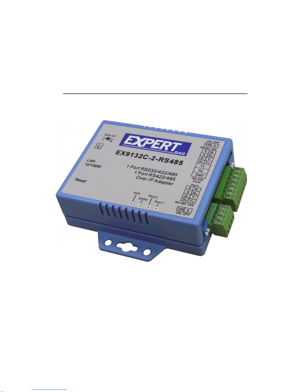
●No. of Ports : RS-485/422*1 Port and RS-232/422/485(Auto-Detect) * 1 Port
●Port Type:Terminal Block : (4pin-RS485/422)*1 and (7pin-RS-232/422/485)*1
●Speed:300 bps∼115.2K bps
●Parity:None , Odd , Even, Mark, Space
●Data Bit:5, 6, 7, 8
●Stop Bit:1 , 2
●Port 1
RS-485 Signals : Data+ , Data- (Surge & Over Current Protection)
RS-422 Signals:Rx+ , Rx- , Tx+ , Tx- (Surge & Over Current Protect)
Built-in RS422/RS485 Pull High-Low Resistor
●Port 2:
One RS-232/422⁄485 Port (Auto-Detect)
RS-232 Signals:Rx, Tx, GND
RS-422 Signals:Rx+ , Rx- , Tx+ , Tx- (Surge & Over Current Protect)

9
RS-485 Signals : Data+ , Data- (Surge & Over Current Protection)
Built-in RS422/RS485 Pull High-Low Resistor
Digital I/O Port
Digital TTL I/O * 8 pins
Socket Port Connection:1 Connection
15KV ESD for all signal
Watch Dog Function
Virtual Support Windows 2000 /2003 / XP / Vista / 7
Firmware On-line Updated Via Ethernet
Power:DC 9 – 24 V , 500mA
LED Lamp:
PORT1(Red)/PORT2 (Green)
DI/DO (Red-Blink during data input and output)
LAN (Red for 10 Mbps ; Green for 100 Mbps)
SYS (Red-Blink)
Environment:
Operating Temperature:0℃∼70℃
Storage Temperature:-10℃∼80℃
Dimensions:115 * 90 * 27 mm ( W * D * H )
WEIGHT:140 gm
RoHS:Compliant with RoHS
Regulatory Approvals:FCC, CE
WARRANTY:1 year

10
2
2
EX-9132C-2RS485
Description & Installation
Product Panel Views
Top Side
DC-In
Power Outlet
Ethernet LAN Port
Serial I/O Port
RS-485/422
Serial I/O Port
RS-232/485/RS-422
LED Indicators
Reset Button

11
Right Side
Serial I/O Port of RS-485/422 and RS-232/422/485
Connect the serial data cable between the converter device and the serial devices.
Follow the parameter setup procedures to configure the converter (see the following
chapters).
Digital I/O
Through EX-9132C-2RS485 , D I/O can transform the status of sensor into the
TCP/IP package data and send out by Ethernet Data Stream (The
EX-9132C-2RS485 must indicate the IP address and COM Port) or activate the
indicated Digital output (Remote WinSock must indicate the EX-9132C-2RS485).
Connect the data wires between the EX-9132C-2RS485 and the
RS232/RS-485/RS-422 device. Follow the parameter setup procedures to configure
the converter (see the following chapters).
RS-485/422
RS-232/485/422

12
Left Side
Power Supply
EX-9132C-2RS485 TCP/IP converter device is powered by a single 9VDC (inner
positive/outer negative) power supply and 500mA of current. A suitable power supply
adapter is part of the packaging. Connect the power line to the power jack at the left
side of EX-9132C-2RS485 TCP/IP converter device and put the adapter into the
socket. If the power is properly supplied, the “SYS” red color LED will be on..
Ethernet LAN Port
The connector for network is the usual RJ45. Simply connect it to your network
switch or Hub. When the connection is made, the LAN LED indicator will light up.
When data traffic occurs on the network, red PORT LED indicator will blink during
data transferring and receiving.
Reset Button
If by any chance, you forget the setup password, or have incorrect settings making
TCP/IP converter inoperable. First, turn on the power. Second, use any point tip to
push this button and hold it about 3 seconds All the parameters will be reset to the
factory default. But do not over 5 seconds , it will enter update mode
Ethernet LAN Port
Reset Button
DC-In
Power Outlet

13
LED Indicators
PORT-1 (Red):
Port1 data transmitting indicator (When data are sending to the network, the LED will
blink.)
PORT-2 (Green):
Port2 data transmitting indicator (When data are sending to the network, the LED will
blink.)
DI/DO (Red):
Data input/output indicator (When data are input/output by the network, the LED will
blink.)
SYS (Green):
It is a device statues indicator (When EX-9132C-2RS485 is operated in normal
statues, the LED will blink once per second.)

14
Wiring Architecture
RS-232 Wiring Architecture
RS-422/RS-485 Wiring Architecture

15
When you finish the steps mentioned above and the LED indicators are as shown in above
diagram, the converter is installed correctly. You can use the Setup Tool “EXBrowser.exe”
to setup the IP Address.
To proceed the advanced parameter setup, please use a web browser (IE or Netscape) to
continue the detailed settings.

16
3
3
EX-9132C-2RS485 Converter Configuration
Initial IP Configuration
When sett up your converter for the first time, the first thing you should do is to configure
the IP address. This chapter introduces the method to configure the device server’s IP
address. For more details about network settings, please see the Network Settings section
in Chapter3, “Web Console Configuration”.
The following topics are covered in this chapter:
□
□
□
Device Management Utility
□
□
□
EXBrowser “View”
□
□
□
EXBrowser “Modify IP”
□
□
□
EXBrowser “Modify MAC”
Device Management Utility
Note:EXBrowser also can use on EX-9132C-2RS485
On PC we provide a Device Management Utility named “EXBrowser.exe” which is an
executable program in Windows 32-bit environments. EXBrowser setup tool is used to
detect and setup the installed converters. It uses UDP broadcast packets to query and
configure converters on the network.

17
When you activate the tool, it will detect the existence of the installed converters and
depict the converters’ status such as IP address, Subnet Mask, MAC Address, and
Device ID (see Figure 3.1). The Setup Tool only can setup one converter at a time.
Thus if there are more than one converter on the network, please shut down or
disconnect other converters. Otherwise the EXBrowser.exe can not detect the converter.
Due to the nature of broadcast UDP packets, EXBrowser has following characteristics:
□
□
□Broadcast packets are not limited by subnet. Even if the IP address of the converters
and the computer running EXBrowser that do not belong to the same subnet, it still
works fine.
□
□
□Broadcast packets can not pass routers. EXBrowser can only be used to monitor
devices with computer running EXBrowser in the same segment of local area
network.
Note:EXBrowser also can use on EX-9132C-2RS485
(Figure 3.1)

18
EXBrowser “View”
□
□
□View -> Refresh
There are two ways for refreshing the status of existing devices. You may
select the item “View” to refresh the status of existing devices on LAN.
Another is to click the icon as red color remark as below. EXBrowser will send
another query to get updated information. (see Figure 3.2).
Note: Always run the “Refresh” after any data change.
(Figure 3.2)
□
□
□File -> Exit Alt+F4
Exit from the program (see Figure 3.3).
(Figure 3.3)
EXBrowser “Modify IP”
□
□
□Modify IP -> Dialog Frame
To click the device on the existing devices list in the EXBrowser table and then the
function bar will be enable. To press second icon of “Modify IP” on function bar
and a dialog frame table will be shown (see Figure 3.4).

19
(Figure 3.4)
Assign an IP Address with the same Subnet Mask of your computer, avoiding any
IP conflict with other network devices.
When you press “Confirm” button, the IP address will be refreshed in 2~3 seconds.
(Figure 3.5)
After click “Confirm” button and then “Input Password” request will be pop-up on
screen (see Figure 3.5). Please simply press “Confirm” button and the new device’s
IP will be changed and save in table, if you changed it.
(Figure 3.6)
Table of contents
Other Expert Media Converter manuals