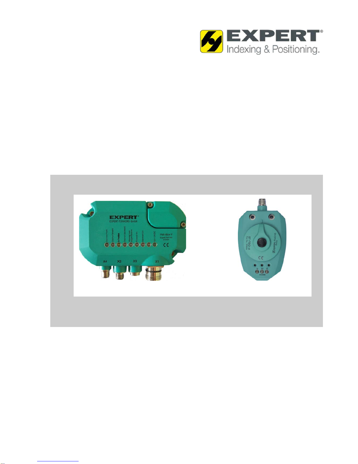
Turntable control SmartTurn
Table of contents
Dok-ID:EXPERT-0003-EN-2011 3
1General Information...............................................................5
1.1 Information about this manual .......................................5
1.2 Explanation of symbols..................................................6
1.3 Disclaimer......................................................................7
1.4 Copyright........................................................................7
1.5 Replacement parts.........................................................8
1.6 Guarantee terms............................................................8
1.7 Customer service...........................................................8
2Safety ......................................................................................9
2.1 Responsibility of the customer.......................................9
2.2 Personnel requirements...............................................10
2.2.1 Qualifications................................................10
2.3 Intended use................................................................11
2.4 Environmental protection.............................................12
3Technical data - turntable controller..................................13
4Structure and function ........................................................14
4.1 Overview......................................................................14
4.1.1 Device description........................................15
4.2 Functional description..................................................16
4.2.1 Standard mode.............................................17
4.2.2 Special mode................................................18
4.2.3 0-position optimization..................................20
4.2.4 Brake wear monitor ......................................22
4.2.5 Overrun monitor ...........................................23
4.2.6 System monitoring........................................23
4.2.7 Device settings - control unit........................24
4.3 Connections.................................................................27
4.3.1 Control unit, see Fig. ....................................27
4.3.1.1 Pin assignment control unit...........28
4.3.2 Sensor, see Fig. 1 ........................................30
4.3.2.1 Pin assignment sensor..................30
4.4 Optional components and accessories........................31
5Installation and commissioning.........................................32
5.1 Safety...........................................................................32
5.2 Mounting instructions...................................................33
5.2.1 Connecting to the power supply...................33
5.3 Electrical installation ....................................................34