EXPO MiniPurge ML303 User manual


ML303 | v19
Page
1
Expo Technologies UK
T: +44 (0) 20 8398 8011
E: sales@expoworldwide.com
Expo Technologies US
T: +1 (440) 247 5314
E:sales.na@expoworldwide.com
Expo Technologies China
T: +86 532 8906 9858
E: qingdao@expoworldwide.com
1. Specification Sheet
See Test, Inspection and Setting Sheet supplied loose with the system.
Refer to drawings for dimensions, weights and electrical ratings.
2. General Information
Application Suitability
•MiniPurge Interface Units (MIU) are certified for use in Hazardous Locations, where the
Hazardous Location is non-mining (i.e. above ground) and where the hazard is caused by
flammable gases, vapours or combustible dusts.
•The MIU can be in Zone 1, 2 for gas and / or Zone 21, 22 for dust, or Class I, Division 1, 2
for gas and / or Class II, Division 1, 2 for dust Hazardous Locations.
•MiniPurge Interface Unit may be used for hazards of most gas or dust groups. However,
apparatus associated with the MIU, such as intrinsically safe signalling circuits and other
flameproof enclosures containing switching devices may be limited in their own group. The
certification documentation supplied with such devices must be checked to ensure their
suitability.
•As with all equipment for use in Hazardous / Classified areas, local working and installation
practices for Hazardous Location equipment must be adhered to when installing and
maintaining this equipment. This equipment must only be installed by personnel who are
aware of the requirements for installation of electrical equipment within hazardous locations.
•MIUs are designed to be controlled primarily with compressed air. Where compressed inert
gases are used (Nitrogen, for example) the user must take suitable precautions so that the
build up of the inert gas does not present a hazard to health. Consult the Control of
Substances Hazardous to Health (COSHH) data sheet for the gas used or relevant national
requirements.
•The following materials are used in the construction of MiniPurge Interface Units. If
substances that will adversely affect any of these materials are present in the surrounding
environment, please consult EXPO for further guidance:
▪Stainless Steel
▪Brass
▪Aluminium ( Ex d / Xp enclosure contains <1% magnesium)
▪Nitrile (‘O’ Rings)
•This equipment is designed for use under normal industrial conditions of ambient
temperature, humidity and vibration. Please consult EXPO before installing this equipment
in conditions that may cause stresses beyond normal industrial conditions.
System Description
•EXPO range of MIUs is designed for use on a wide range of applications and enclosures.
They are to be used in conjunction with a system, which provides the MIU with the
necessary signals in order to produce “Volt Free / Dry Contact” alarm signals and power
switching to the pressurized enclosure.
•All units are built into flameproof / explosionproof enclosures. The joint between the lid and the
enclosure forms a threaded flamepath.

Page
2
ML303 | v19
Expo Technologies UK
T: +44 (0) 20 8398 8011
E: sales@expoworldwide.com
Expo Technologies US
T: +1 (440) 247 5314
E:sales.na@expoworldwide.com
Expo Technologies China
T: +86 532 8906 9858
E: qingdao@expoworldwide.com
•Each MIU is supplied with limited entries (refer to the drawing section for details). When
additional entries have been ordered, the following restriction will apply:
oMinimum space between entries;
▪35mm, (1.38”) for M20 or ½” NPT
▪40mm, (1.58”) for M25 or ¾” NPT
oEntries should not be placed so close to the side that an internal surface, parallel to the
thread of the entry, is cut when a threaded entry is machined.
•For USA (NEC) or Dual standard conformity, NPT entries must be used.
•For IEC / ATEX, metric or NPT entries may be used. NPT and Metric entries must not be
mixed on the same enclosure.
•The standard MIU is supplied with NPT entries.
•Alternative versions of MIU are available which use intrinsically safe or increased safety
switching systems to control the MIU functions. These are only available to special order.
Contact the sales office for details.
The standard range of MIUs consists of 3 types:
MIU/dA AMU-9AA1-510
Power contactor: 4PNO/20A//440Vac*
Alarm switch: SPCO3A/250Vac*
110Vac Coil for electrical override when required
AMU-9AA1-511
Power contactor: 4PNO/20A/440Vac*
Alarm switch: SPCO3A/250Vac*
230Vac Coil for electrical override when required
AMU-9AA1-518
Power contactor: 4PNO/20A/440Vac*
Alarm switch: SPCO3A/250Vac*
24Vdc Coil for electrical override when required
MIU/dX AMU-AAA1-610
Power contactor: 4PNO/20A/440Vac*
Signal relay: 4PNO/5A/250Vac*
Alarm switch: SPCO3A/250Vac*
110/230Vac Dual voltage supply
MIU/dT AMU-BAA1-610
Power contactor: 4PNO/35A/600Vac*
Signal relay: 4PNO/5A/250Vac*
Alarm switch: SPCO3A/250Vac*
110/230Vac Dual voltage supply
*IEC rating shown, refer to drawings for detailed information on ratings including UL and CSA.

ML303 | v19
Page
3
Expo Technologies UK
T: +44 (0) 20 8398 8011
E: sales@expoworldwide.com
Expo Technologies US
T: +1 (440) 247 5314
E:sales.na@expoworldwide.com
Expo Technologies China
T: +86 532 8906 9858
E: qingdao@expoworldwide.com
3. Installation
•MiniPurge Interface Units are designed to be mounted in hazardous / classified locations. The
MIUs are suitable for use in the following area classification. Please note that the gas group
varies for European / USA area classifications.
IEC / Europe
Zone 1, 2
Zone 21, 22
Gas Group IIC
Dust
USA/ Canada
Class I, Divisions 1 & 2
Class II, Divisions 1 & 2
Gas Groups B, C & D
Dust Groups E, F & G
•The MiniPurge Interface Unit shall be installed in accordance with relevant standards, such
as EN 60079-14 or NEC 500 or 505, and / or any local codes of practice that are in force.
•The distance required free from obstructing the flamepath for ATEX / IEC:
▪Gas Group IIC is at least 40mm (15/8”).
▪Gas Group IIB is at least 30mm (1 11/64”)
▪Gas Group IIA is at least 10mm (17/64”)
•Cable glands, conduit or other cable entry devices shall be appropriately certified and
suitable for the cable and the conditions of use and be installed in accordance with the
manufacturer’s instructions. EN 60079-14 contains guidance on the selection of appropriate
cable glands.
•When the MiniPurge Interface Unit is to be used in
conjunction with a MiniPurge Purge and Pressurization
System, it shall be connected in accordance with the
instructions given in this manual.
•The external earth connection of the MiniPurge Interface
Unit shall be connected to earth using a minimum 4mm2/
12 AWG conductor.
•It is recommended that 6 mm / ¼” dia non-crushable pipe
with appropriate 1/8” NPT fittings (not supplied) are used to
connect the MIU with the MiniPurge system.
To order suitable fittings and pipe to connect the two units
see Spare Parts - Additional Items.
•MiniPurge Interface Units are supplied with NPT tapped
cable entries as standard.
•In the MIU/dA, Power Contactor is operated directly by the
pneumatic (input) Actuator.
•In the MIU/dX, connect the external voltage between the
terminals N and 115 or 230 terminals, for 115 V or 230 V ac
Power Supply respectively.
•In the MIU/dT, connect the external voltage to the L and N
terminals, and select the appropriate supply voltage using the
voltage selector switch, for 115V or 230V ac supply
respectively.
•Refer to the drawing section of this manual for the wiring
schematic of the unit to be installed. Also refer to Project
Specific Data for possible additional information.

Page
4
ML303 | v19
Expo Technologies UK
T: +44 (0) 20 8398 8011
E: sales@expoworldwide.com
Expo Technologies US
T: +1 (440) 247 5314
E:sales.na@expoworldwide.com
Expo Technologies China
T: +86 532 8906 9858
E: qingdao@expoworldwide.com
4. Commissioning
•Once the MIU has been installed, the cable glands, conduit, earth connections and any other
connections (e.g. pneumatic) shall be inspected for correct installation before the unit is put
into service.
•Apply a thin, even layer of the grease (provided) onto the threads of the lid.
•The lid shall be correctly fitted, and the lid locking device secured.
•If the commissioning is being carried out in the Hazardous Location, appropriate precautions
must be taken to prevent an incident. A relevant “Hot Work Permit” or similar must be obtained
from the appropriate authority and regulations followed.
Commissioning the MIU when installed with a MiniPurge Control System
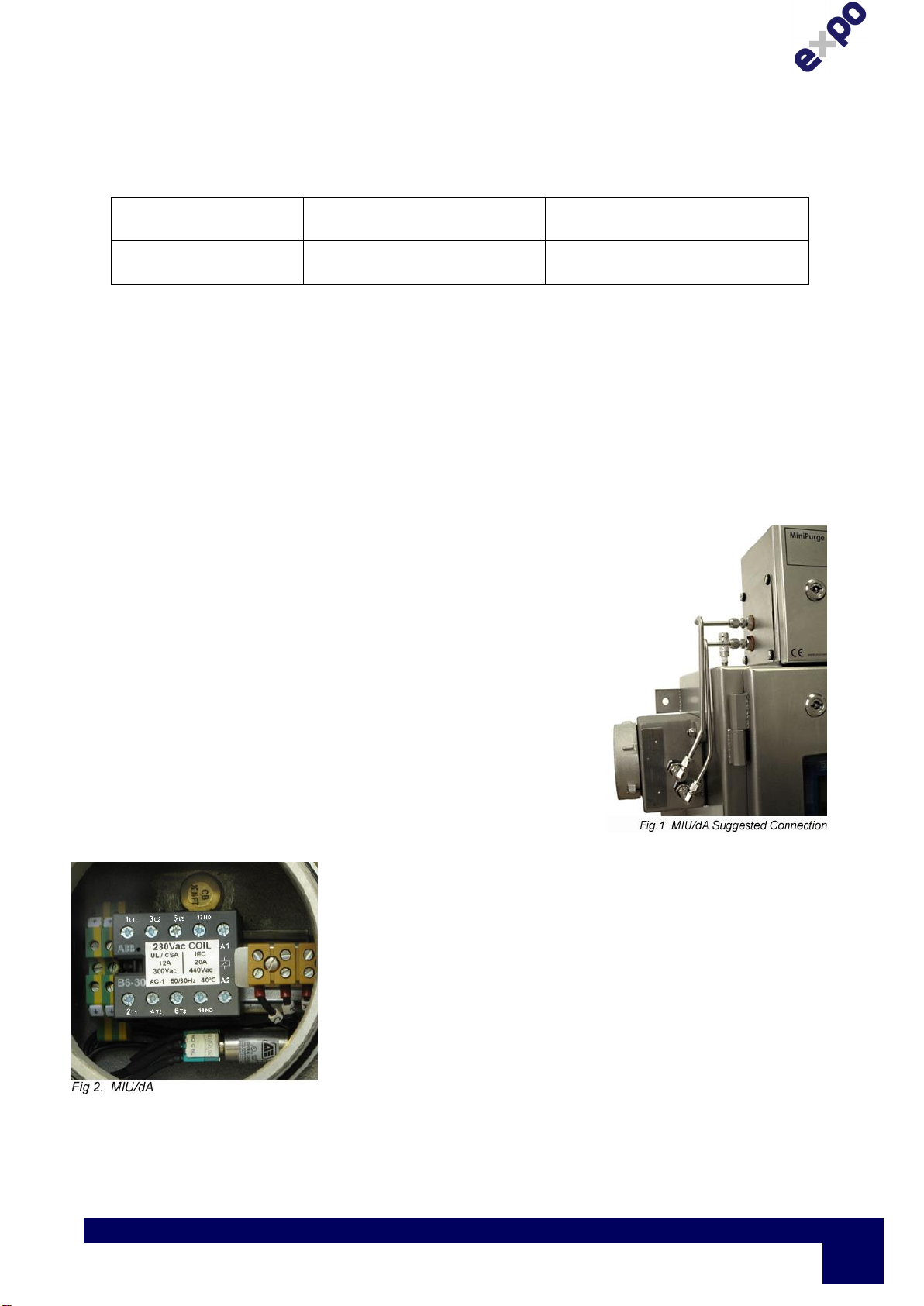
•Commissioning the MIU requires a working pressurized enclosure and MiniPurge system. For
operation and commissioning instructions for the MiniPurge system, refer to the appropriate
manual supplied with the MiniPurge. The description below assumes a standard Leakage
Compensation MiniPurge is in use.
•Operation of the Alarm / Pressurized contact can be tested as follows:
•With the air supply turned off, there should be continuity between the A and C terminals, and
no continuity between the C and P terminals.
•Close the enclosure door and turn the air supply on. The purge should begin, and the
Pressurized indicator on the MiniPurge should change from “Red” to “Green”. There should
now be continuity between the C and P terminals, and no continuity between the C and A
terminals of the MIU.
•Operation of the power switching contacts can be tested as follows:
•With the air supply off, the power switching contacts should be open circuit. Remember to turn
on the power supply, for units that require a power supply to control the switching (MIU/dX and
MIU/dT units).
•Close the enclosure door. Turn on the air supply. The purge cycle should begin.
•Once the purge cycle has been completed the power switching contacts will close. Both
pneumatic connections between the MiniPurge and MIU are now pressurized,
•Ensure the pneumatic connections do not leak.
•The final check is the most important and must not be ignored. The enclosure should be
pressurized, a purge cycle completed, and the power contacts closed. Turn the air supply to
the MiniPurge off. After a few seconds the enclosure will lose pressure and the following
should happen
oThe Pressurized indicator on the MiniPurge should change from “Green” to “Red”.
oThe power contacts should open disconnecting power to the enclosure.
oThere should be continuity between the A and C terminals, and no continuity between
the C and P terminals.
oThe above assumes the MiniPurge system is set to “Alarm & Trip” (i.e. Disconnect) not
to “Alarm Only”
•If the final check has been completed successfully, turn on the air supply to the MiniPurge.

ML303 | v19
Page
5
Expo Technologies UK
T: +44 (0) 20 8398 8011
E: sales@expoworldwide.com
Expo Technologies US
T: +1 (440) 247 5314
E:sales.na@expoworldwide.com
Expo Technologies China
T: +86 532 8906 9858
E: qingdao@expoworldwide.com
5. Maintenance
EXPO suggests at a minimum of every six months and /or a maximum of 2 years dependent on
site conditions, to follow the maintenance routine described below:
•Inspect the condition of the enclosure and associated cable glands, conduit for any signs of
damage.
•Inspect the condition of the thread and the lid locking device for any signs of corrosion or
damage.
•There are no user serviceable parts within the MIU system apart from those mentioned in
this manual.
•Repeat the commissioning tests to check correct operation of the system.
•Check that the air supply quality, where applicable, is still acceptable.
•Check that the system has not been modified in an unauthorised manner.
•Check that the certification labelling is legible and that the system is suitable for the
hazardous location.
6. Fault Finding
Refer to the table below to solve any malfunction.
Problem
Potential Cure
The Alarm/Pressurized contact
fails to operate.
•Check the pneumatic connection from the MiniPurge for
leakage / blockage.
•Check the operation of the pneumatic feed through as
follows:
•Unscrew the air connection to the Feed Through Actuator
on the side of the MIU and use a small terminal
screwdriver to manually depress the piston inside the
feed through.
•Pressing the piston should transfer the motion to the
switch within the MIU, and the change-over action of the
switch should be observed with a continuity tester.
The power switching contacts
do not close. (MIU/dA units)
•The contactor is directly operated by the pneumatic Feed
Through Actuator. Operation should be tested as outlined
for the alarm contact above.
The power switching contacts
do not close (MIU/dX and
MIU/dT units)
•Check that there is power supplied to the MIU
•Check operation of the pneumatic Feed Through
Actuator as above for the Alarm/ Pressurized contact.
•Check the voltage selection matches that of the supply
•Check the fuse in the MIU. (Refer to the circuit diagram
for the fuse rating.)

Page
6
ML303 | v19
Expo Technologies UK
T: +44 (0) 20 8398 8011
E: sales@expoworldwide.com
Expo Technologies US
T: +1 (440) 247 5314
E:sales.na@expoworldwide.com
Expo Technologies China
T: +86 532 8906 9858
E: qingdao@expoworldwide.com
7. Spare Parts List
Attention: When ordering spare parts include the serial number of the unit.
Item Part Number
Type dA
Contactor (110 Vac Coil) 4PNO/20A/440Vac ECT-T000-064
Contactor (230 Vac Coil) 4PNO/20A/440Vac ECT-T000-063
Type dX
Contactor (24 Vac Coil) 4PNO/20A/440Vac ECT-T000-065
Relay 4PNO/5A/250Vac ECT-T000-025
Fuse Assembly, 250mA EFH-0400-001
Type dT
Contactor (24 Vac Coil) 4PNO/35A/600Vac ECT-T000-024
Relay 4PNO/5A/250Vac ECT-T000-025
Fuse, 630mA EFU-C006-301
Additional items
Direct Mounting Kit, for dA & Size 1 MiniPurge only KMP-2600-000
ensure MIU is ordered with additional holes E & F
Grease PCB 10g sachet S0130/001
Mechanical Manual Override for dA only AGM-GM00-428
Mechanical Manual Override for dX & dT. AGM-GM00-452
Electrical Manual Override UL MO/UL
Electrical Manual Override ATEX, IEC MO(BOX)or MO(PM)
Pipe fittings to connect MiniPurgeto MIU, contains; KMP-3MIU-S00
4 x 1/8” NPT to 6mmOD, Stainless Steel
Pipe 6mmOD in Stainless Steel, sold in 1m (39”) lengths HTS-0601-500
Plug, ½” NPT, Brass, Sira 00ATEX1073U TTP-4400-0B0

ML303 | v19
Page
7
Expo Technologies UK
T: +44 (0) 20 8398 8011
E: sales@expoworldwide.com
Expo Technologies US
T: +1 (440) 247 5314
E:sales.na@expoworldwide.com
Expo Technologies China
T: +86 532 8906 9858
E: qingdao@expoworldwide.com
8. Certificates
For limitations and conditions of use refer to the applicable certificate at the back of this
manual:
Sira 02ATEX1129 0518 II 2 G D
Tamb -20°C +40°C Ex db IIC T6 Gb
Ex tb IIIC T80ºC Db
Tamb -20°C +55°C Ex db IIC T5 Gb
Ex tb IIIC T95ºC Db
IECEx SIR07.0008 Tamb -20°C +40°C Ex db IIC T6 Gb
Ex tb lllC T80ºC Db
Tamb -20°C +55°C Ex db IIC T5 Gb
Ex tb lllC T95ºC Db
INMETRO TÜV 12.1464 Tamb -20°C +40°C Ex db IIC T6 Gb
Ex tb lllC T80ºC Db
IP66
Tamb -20°C +55°C Ex db IIC T5 Gb
Ex tb lllC T95ºC Db
IP66
NOIV.E203605* & FTRX.E181300*
* These certificates are for the Power Interlock Actuator used on the MIU/d, where the UL label
must be removed during assembly.
9. Drawings and Diagrams
See attached drawings:
TITLE Drawing Number
MiniPurge Interface Unit Installation XBR-MTD0-001
MIU in dA enclosure** AMU-9AA1-510
MIU in dX enclosure** AMU-AAA1-610
MIU in dT enclosure** AMU-BAA1-610
Key Mechanical Pneumatic Manual Override AGM-GM00-428
Direct Connection Kit Size 1 MP to MIU (for dA only) KMP-2600-000
Cat 5 UTP Network Connections
** These parts have AutoCAD.dwg blocks available
from Expo upon request. The aim of a block is to allow
Engineers and users to quickly build up a GA of an
enclosure using Expo standard parts.

Page
8
ML303 | v19
Expo Technologies UK
T: +44 (0) 20 8398 8011
E: sales@expoworldwide.com
Expo Technologies US
T: +1 (440) 247 5314
E:sales.na@expoworldwide.com
Expo Technologies China
T: +86 532 8906 9858
E: qingdao@expoworldwide.com
10. Project Specific Data
Recorded below are the drawing numbers detailing items specific to the project the MIU/d is
supplied to.
Drawing Number
Title
1
2
3
4
5
6


FLATNESS TO BE LESS THAN 0.4mm OVER ANY 100mm LENGTH
UNSPECIFIED
TOLERANCES
MATERIAL
DR'WN
APP'D
CHK'D
DRAWING STATUS:
APPROVED:
MOD. No:
DATE:
ISSUE:
3rd ANGLE
PROJECTION
DIMENSIONS IN mm
DO NOT SCALE
Expo Technologies Limited
JOB No:
FINISH
TITLE
CUSTOMER: SHEET No. OF
SURREY KT7 0RH
UNITED KINGDOM
DRAWING No.
SCALE
The contents of this drawing / document are Copyright ã Expo Technologies Limited. They are to be treated as confidential and are returnable
upon request. They are not to be copied or communicated in part or in whole without written consent from Expo Technologies Limited, neither
are they to be used in any way against our interests.
NO DEC PLACE ±0.5
1 DEC PLACE ±0.2
2 DEC PLACE ±0.1
NOTES
EXPO EXPLOSIONPROOF PRODUCTS ARE DESIGNED TO FULFIL THE APPLICABLE REQUIREMENTS OF IEC,
ATEX & NEC ARTICLE 500 HAZARDOUS (CLASSIFIED) LOCATION INSTALLATIONS.
THIS MINIPURGE INTERFACE UNIT IS SUITABLE FOR USE IN THE FOLLOWING HAZARDOUS LOCATIONS:
CLASS I DIV 1 GROUP B, C & D, UL COMPLIANCE
CLASS II DIV 1 GROUP E, F & G NEMA 4, 7 & 9
SIRA 02ATEX1129 II 2 GD
ZONE 1 GAS GROUP IIC Ex d IIC T6 (Tamb -20°C TO +40°C) OR T5 (Tamb -20°C to +55°C)
ZONE 21 DUST Ex tD A21 IP6X T80°C OR T95°C (Tamb -20°C to +55°C)
IECEx SIR07.0008
ZONE 1 GAS GROUP IIC Ex d IIC T6 (Tamb -20°C TO +40°C) OR T5 (Tamb -20°C to +55°C)
ZONE 21 DUST Ex tD A21 IP6X T80°C OR T95°C (Tamb -20°C to +55°C)
WEIGHT: 3kg (6.5lbs)
COIL IS ONLY USED AS PART OF ELECTRICAL MANUAL OVERRIDE, WHEN REQUIRED.
52
1
DESCRIPTION
Ex d / EXPLOSIONPROOF ALUMINIUM HOUSING
CONTACTOR CON1:
UL AND CSA:
3 PHASE: 3HP 480Vac
GENERAL USE: 12A 300Vac
IEC:
AC1 20A 440Vac T<40°C
AC1 16A 440Vac T<55°C
AC3 4kW 400Vac T<55°C
AC3 9A 400Vac T<55°C
COIL 50/60Hz at 40°C:
110Vac FOR MIU AMU-9AA1-510
230Vac FOR MIU AMU-9AA1-511
24Vdc FOR MIU AMU-9AA1-518
TERMINAL RAIL
ALARM/PRESSURIZED TERMINAL BLOCK
EARTH TERMINAL BLOCK
POWER INTERLOCK ACTUATOR
ALARM/PRESSURIZED ACTUATOR FOR SW1
UL CSA AND IEC: 6A 125Vac OR 3A 250Vac
RATING LABEL
QTY
1
1
1
3
2
1
1
1
ITEM
1
2
3
4
5
6
7
8
WIRE SIZE FOR CONTACTOR AND TERMINALS: 2.5mm² (14 AWG) MAX
6
7
4
SW1
3
1.
2.
3.
4.
8
PRESSURE ALARM
E E
PRESSURIZED
COMMON
PC A
POWER INTERLOCK
SIGNAL 2 barg (30
psi) MINIMUM FROM
MINIPURGE
110/230 Vac COIL -
SEE NOTE 4
ALARM/PRESSURIZED
SIGNAL
2 barg (30 psi) MINIMUM
FROM MINIPURGE
SW1
POWER SUPPLY
85-254 Vac 50-60 Hz
26
4A2
14
CON1
135A1
13

FLATNESS TO BE LESS THAN 0.4mm OVER ANY 100mm LENGTH
UNSPECIFIED
TOLERANCES
MATERIAL
DR'WN
APP'D
CHK'D
DRAWING STATUS:
APPROVED:
MOD. No:
DATE:
ISSUE:
3rd ANGLE
PROJECTION
DIMENSIONS IN mm
DO NOT SCALE
Expo Technologies Limited
JOB No:
FINISH
TITLE
CUSTOMER: SHEET No. OF
SURREY KT7 0RH
UNITED KINGDOM
DRAWING No.
SCALE
The contents of this drawing / document are Copyright ã Expo Technologies Limited. They are to be treated as confidential and are returnable
upon request. They are not to be copied or communicated in part or in whole without written consent from Expo Technologies Limited, neither
are they to be used in any way against our interests.
NO DEC PLACE ±0.5
1 DEC PLACE ±0.2
2 DEC PLACE ±0.1
EARTH LUG M6
LID CLAMP
M5 (10-32 UNF) TO 1/8" NPTF
ADAPTORS FITTED TO
ACTUATORS
CABLE ENTRY
1/2" NPT
(PLUGGED)
ALARM ACTUATOR
1/8" NPTF
NEMA 4 SEAL (IP66)
POWER ACTUATOR
1/8" NPTF
3 FIXING HOLES
M5 [10-32 UNF]
2 CABLE ENTRIES
1/2" NPT
38 [1 1/2"]
(ACTUATOR ONLY)
130 [5 1/8"]
95 [3 3/4"]
= =
130 [5 1/8"]
= 157 [6 3/16"] =
= 51 [2"] =
= 101.6 [4"] =
60
[2 3/8"]
12 [1/2"]
57
[2 1/4"]
130 [5 1/8"]
30 [1 3/16"]
45 [1 3/4"]
37 [1 7/16"]
33 [1 5/16"]
190 [7 1/2"]
HOLE ø10 (TO SUIT
BOLT SIZE M8 [5/16"] )

FLATNESS TO BE LESS THAN 0.4mm OVER ANY 100mm LENGTH
UNSPECIFIED
TOLERANCES
MATERIAL
DR'WN
APP'D
CHK'D
DRAWING STATUS:
APPROVED:
MOD. No:
DATE:
ISSUE:
3rd ANGLE
PROJECTION
DIMENSIONS IN mm
DO NOT SCALE
Expo Technologies Limited
JOB No:
FINISH
TITLE
CUSTOMER: SHEET No. OF
SURREY KT7 0RH
UNITED KINGDOM
DRAWING No.
SCALE
The contents of this drawing / document are Copyright ã Expo Technologies Limited. They are to be treated as confidential and are returnable
upon request. They are not to be copied or communicated in part or in whole without written consent from Expo Technologies Limited, neither
are they to be used in any way against our interests.
NO DEC PLACE ±0.5
1 DEC PLACE ±0.2
2 DEC PLACE ±0.1
HOLE ø30 [ø1 3/16"]
ALLOW SPACE FOR GLANDS,
CABLES, PNEUMATIC
CONNECTIONS AND PIPES
FIXINGS IN 2 PLACES
MAX ø8 [ø5/16"]
TO SUIT MOUNTING HOLE
ø10 [ø3/8"] IN MIU.
SEE NOTE (b)
WELDED EARTH STUD
WHERE APPLICABLE.
SEE NOTE (a)
NOTE:
WHEN FITTED BY EXPO
TECHNOLOGIES LTD:
THE EARTH STUD WILL BE
M6 x 20 LONG
THE FIXING STUDS WILL BE
M8 x 25 LONG
(a)
(b)
95 [3 3/4"]
33 [1 5/16"]
35 [1 3/8"] = 157 [6 3/16"] =


Table of contents