ExpressWeld Plasma 60 - Ultra User manual
www.askaynak.com.tr
Expressweld Model: Plasma 60-ULTRA
Inverter Plasma Cutting Machine
USER MANUAL
Cutting with Plasma Arc
Cutting Method and Specifications
380V - 3Ph
Cutting
Thickness
20mm
Phase

Kaynak Tekniği Sanayi ve Ticaret A.Ş.
TOSB Otomotiv Yan Sanayi İhtisas Organize Sanayi Bölgesi
2. Cadde, No: 5, Şekerpınar 41480 Çayırova, KOCAELİ
Phone: (0262) 679 78 00 Fax: (0262) 679 77 00
www.askaynak.com.tr
MANUFACTURER
Manufactured in People's Republic of China by KAYNAK
TEKNİĞİ SANAYİ ve TİCARET A.Ş.
Safety In Cutting With Plasma Arc
General Features
Installation and Operator Instructions
Preparation to Work
Accessories Given With The Machine
Maintenance and Troubleshooting
Electromagnetic Compatability
Efficient Use of Machine In Terms of Energy Consumption
Unpacking
Transportation and Storage Conditions
Expiry of Machine's Physical Life
Spare Parts
Electrical Connection Diagram
Contact Addresses
3 - 4
5
6
7 - 9
9
10 - 13
14 - 15
15
16
16
16
17 - 19
20 - 21
22
Table of Contents
December 2014
Physical life determined by Ministry of Industry and Trade is 10 years.
(This is the period for providing spare parts required for the machine to operate.)

"Expressweld"
is the registered trademark of Kaynak Tekniği
Sanayi ve Ticaret A.Ş.
Safety In Cutting With Plasma Arc - 1
3
This machine has been designed to cut metal pieces,
and it cannot be used for any other purpose.
Be sure that this machine should only operated by qualified personnel. Be sure that all installation, operation,
maintenance and repair procedures are performed only by authorized personnel. Be sure to read user guide
carefully before operating the machine. Failure to follow the instructions included in the user guide may cause
serious injury, loss of life and damage on machine. Please read the warnings next to the symbols stated below.
"Kaynak Tekniği Sanayi ve Ticaret A.Ş." is not liable for any damages due to improper connection, storage
conditions and operation procedures.
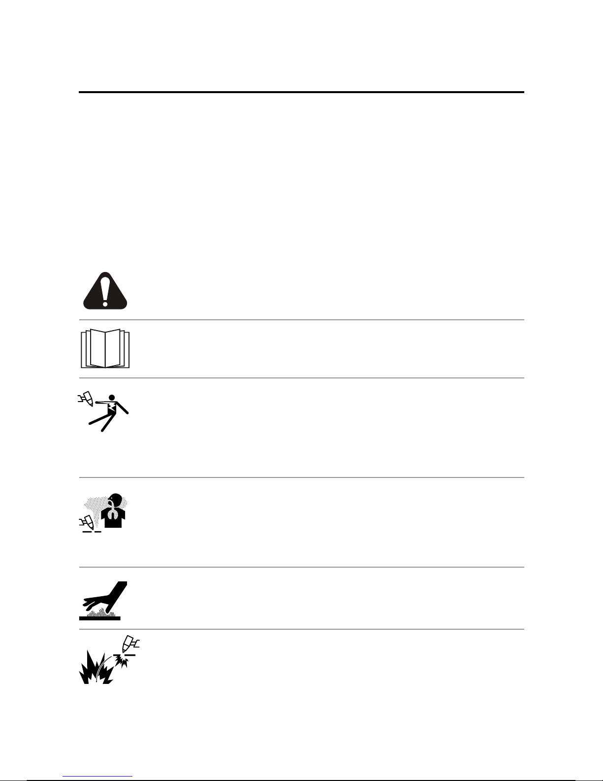
WARNING: This symbol indicates that instructions must be followed to avoid serious
personal injury, loss of life or damage to this equipment. Protect yourself and others.
READ and UNDERSTAND INSTRUCTIONS: Read and understand this manual
before operating this equipment. Failure to follow the instructions in this manual may
cause serious personal injury, loss of life, or damage to this equipment.
ELECTRIC SHOCK MAY KILL: Electric shock danger is the most serious risk that cutting
operator may encounter frequently. Contacting electrically hot parts may cause injuries,
death or falling down due to electric shock and sudden reflex. While machine is operating,
do not touch to the tip of cutting torch, ground connection or live work piece connected to
the machine. Insulate yourself against the tip of cutting torch, grounding connection or work
piece. Immediately after plugging out the power cable, do not touch metal ends of power
cable, there may be electric shock danger.
MATERIAL BEING CUT MAY BURN: High amounts of heat may be produced while cutting
operation. Hot surfaces and material may cause serious burns. While touching or moving this
kind of material, always wear gloves.
FUMES AND GASES MAY BE DANGEROUS: Cutting operation may cause fumes, cut piece
powder and gases that are injurious to health. Always enough ventilation should be used or
fumes, metal powders and gases should be exhausted from breathing place. Generally in
cutting applications; temporary effects for short time can be seen such as face and skin burning,
dizziness, nausea and fever based on exposure period and amount of fume. Long time fume
exposure may cause iron loading and dysfunctions in lungs. Bronchitis and pulmonary fibrosis
are primary effects occurred.
SPARKS FROM CUTTING OPERATION MAY CAUSE FIRE AND EXPLOSIONS. Keep
away fire hazards from cutting area and have a fire extinguisher readily available. Remember
that cutting sparks and hot materials from cutting operation can easily go through small
cracks and openings to adjacent areas. Until ensuring that precautions are used to fully clean
flammable and toxic gases, never perform cutting operation on any tanks, drums, containers
or material. Never operate cutter in places that flammable gases, vapors or liquid fuels exist.
Always keep in mind the fire risk due to high temperatures while performing cutting operation.

Safety In Cutting With Plasma Arc - 2
4
ELECTRICALLY POWERED EQUIPMENT: Turn off input power using the switch at the fuse
box before working on the equipment. Electrical connections should be performed
adequate to the obligated rules.
GROUNDING: For your safety and trouble-free operation, electrical supply cables should
be connected to a proper grounded receptacle.
ELECTRIC and MAGNETIC FIELDS MAY BE DANGEROUS TO HUMAN HEALTH:
Electric that flows through conducters, produces electromagnetic field. This
electromagnetic field can be effective on devices like pacemakers. Users who have a
pacemaker must refer to a physiotherapist before operating the machine.
PLASMA ARC MAY BURN: Use proper mask, filter and protective glassas to protect your
eyes from sparks and the rays of the plasma cutting arc when performing cutting operation or
observing the operation. Skin should be protected by clothing made from flame resistance
material. Protect other nearby personnel with suitable, non-flammable screening and/or warn
them not to watch plasma cutting arc nor expose themselves to the arc rays or to hot spatter or
metal.
When eyes are exposed to UV rays even for a short time, also called as “Getting Welder's
Flash”, it may cause burns in your eyes. Getting Welder's Flash may not be noticed after hours
of exposing, but it is too irritating as well as may cause transient blindness. Normally getting
operator's flash is a temporary situation, but exposing eyes to UV rays for a long time and
frequently may cause permanent damage on eyes. As a protection measure besides not to
watch arc rays, also using cutting goggles having proper filter is necessary. Following table
may be useful for choosing proper filter for plasma cutting applications.
ELECTRICALLY POWERED EQUIPMENT: Periodically inspect the conditions of cutting
torch cables, supply cables and cables connected to the equipment. If you notice any
improper situation, immediately replace damaged parts with the new ones. To prevent the
risk for every kind of arc glare and fire, never leave the cutting torch on the desk where the
cutting operation is performed or any surface in contact with work clamp.
SAFE USAGE: This machine is suitable for cutting in environments where there is high
electric shock risk.
MOVING PARTS MAY HURT YOUR HANDS: Keep your hands away from fan and moving
parts within the machine.

Advantages provided by EXPRESSWELD Plasma 60-ULTRA plasma cutting machine:
1 - High quality cutting by smooth DC current,
2-
3-
4-Wide application area,
5-Lightness and easy transportation, easy installation and operation,
6-
Stable cutting arc,
Creating easy cutting arc opportunity with high open circuit voltage,
2 (two) years service guarantee as of purchase date.
General Features
Physical Dimensions
Height
440 mm
Width
240 mm
Length
550 mm
Weight
25.5 kg
Operating Temperature between - 10°C and + 40°C
Insulation Class: H
Degree of Contamination: 3
Compressed Air
Required Input Pressure
4.5 - 5 bars
Input Power
Input Voltage
380 V ± % 10/3 Phase
Power Taken From Mains
6.9 kW (at 50% duty cycle)
Frequency
50/60 Hertz (Hz)
Cutting Current Output Values
Duty Cycle
(10 minutes period)
% 50
% 100
Output Current
(Amper)
60 A
43 A
Output Range
Cutting Current Range
22 - 60 A
Max. Open Circuit Voltage
310 V (DC)
Power Factor (cos : 0.72 (at 50%)
Output Voltage
(Volt)
104 V (DC)
97 V (DC)
Input Cable and Fuse Type
Delay Action Fuse Value
20 A
Mains Input Cable
4 x 2.5 mm²
EXPRESSWELD Plasma 60-ULTRA, is a inverter plasma cutting machine which is manufactured by using the
latest inverter technology and inverter plasma cutting power units is a technology that has been emerged as of
1980s in international market. 50Hz/60Hz frequency is converted to 20 KHz and higher, in other words to high
frequency by IGBT, and then alternating current (AC) in converted to direct current (DC) by decreasing the
voltage, in inverter technology a powerful DC cutting current is produced by using PWM technique, thanks to
inverter technology, dimensions and weight of the plasma cutting machine has been decreased significantly and
its productivity has been increased 30%. Issues like stabile arc creation, safety, lightness and energy saving are
the most important features of plasma cutting machines manufactured by using inverter technology.
Development of inverter plasma cutting machines is characterized as a revolution in cutting field by the experts.
5

Installation and Operator Instructions
Location and Environment (Read entire section carefully before installing and operating the machine):
For long economical life and safety operation, it is useful to take some simple precautions stated below:
1 - Do not place the machine on a surface with a slope over 15° and do not operate on such surface.
2- Only use the plasma cutting torch given with the machine. Do not use any other torch.
3- Machine should always be operated in an environment having clean airflow and there should be no obstacle
that prevents ventilation or stops airflow. Do not cover the machine while operating with paper, cloth or similar
objects.
4- Dust and dirt may enter into machine. This should be reduced as much as possible. Do not operate the
machine in extremely dusty locations and environments having water, paint and oil particles and also
grinding dusts and abrasive gases in its atmosphere.
5- This machine has IP21S protection. Keep the machine dry as much as possible and do not place it on wet
ground or in puddles.
6- Plasma cutting machine should be used in places with good environment lighting and should not be used in
dark places. Also the plasma cutting machine has been designed to be used indoors and is not suitable for
using under sunlight, rain and snow. Do not use plasma cutting machine to defrost pipes.
7- Place the machine far away from radio controlled devices. Normal operation of the machine may interfere with
this kind of devices nearby and in such case may cause injury or failure of the equipment. Please read
“Electromagnetic Compatibility" section included in this manual.
8- Do not use this machine at ambient temperatures below -10°C and above +40° C and in environments having
more than 70% humidity level. Heating tests have been performed in ambient temperature and operation
cycle has been determined with simulation at 40°C.
9- If the frame cover is opened and interfered by people who are not qualified for electrical equipments, life-
threatening danger may occur. In case behaving on the contrary, be regarded as accepting beforehand all
potential negative consequences.
10- Thanks to 3 phase 380 VAC input power and its max 60 A cutting current, it enables cutting low alloy
steels up to 20 mm thickness.
6

Preparation to Work -1
Duty Cycle and Overheating:
Input Cable Connection / Controller and Usage Features:
Before starting the machine, check input voltage, phases and frequency. Input voltage values to be used are
determined in “Specifications” sections of the user manual and in the plate located on the machine. Make sure
that the grounding of the cables connecting the machine to mains supply are suitable and sufficient amount of
current for normal operation of the machine can be supplied. Cutting machine can only be connected to a
mains which is protected with a 20 amperes delay action fuse.
1- This machine has been designed as to work with 3 phase, 380 V (AC) and 50-60 Hz supply voltage.
It should only be operated on 3-phase grounded systems.
2- Never perform a mains supply connection and start the machine until there is a good protective
ground connection approved by a qualified electrician. Electric leakages constitute death risk for
human health.
CONTROL UNITS OF FRONT AND REAR PANELS:
1 - Power Indicator Warning Lamp: Indicates that the machine is active.
2 - Cutting Current Adjusting Knob: Adjusts the current value required for cutting.
3 - Cutting / Gas Test Selection Switch: Air test switch
4 - Work Cable Connector: Work cable connection is made.
5 - Plasma Cutting Torch Connector: Plasma cutting torch connection is made.
6 - Barometer: Indicates the air pressure being used.
7 - Ready to Cut Warning Lamp: Indicates that the machine is ready for cutting.
8 - Torch / Air Pressure Warning Lamp: In case of any fault on plasma cutting torch or an abnormal
situation on air pressure, it is activated to warn the operator.
9 - Overload and Overheating Warning Lamp: Indicates that the machine entered into thermal protection.
10 - On/Off Switch: Controls the input of supply current to the machine.
11- Air Input Connector: Enables connection of compressed air to cutting machine.
12 - Energy Input Cable: Supply cable that will be used for machine's mains connection.
The efficiency of the machine is the percentage of the rating of the operator performing cutting process without
overheating and stopping for 10 minutes with the cutting current given.
Machine is protected from overheating by its thermal protection. When this protection is enabled, warning light
on front panel lits. When you return to the safe operating temperature the light turns off and you may continue
cutting.
7

Preparation to Work -2
10
11
12
REAR PANEL
1
2
3
6
45
7
98
FRONT PANEL
8

Preparation to Work -3
Accessories Given With Machine
Plasma cutting torch
Work cable
Cutting Operation with Plasma Arc:
Before starting to plasma cutting operation, following procedures should be performed:
1 - Connect plasma cutting torch to the machine.
2 - Connect work clamp to the machine.
3 - Connect other end of work clamp to the surface of the work piece which is unpainted, rustless and clean
as its ends contact completely.
4 - Connect compressed air hose to ir Input Connector”. To enable plasma operation, adjust air pressure “A
between 4.5 - 5 bar on air regulator. Adjust in SET mode. Barometer should indicate 0,45-0,5 Mpa.
5 - Connect power cable to electric supply system.
6 - Before starting to cutting operation, perform the following checks:
a - Make sure that the plasma cutting machine is grounded safely.
b - Make sure that all contact surfaces, especially the connection between clamp on the tip of work cable
and work piece are performed firmly.
c - Check whether the plasma cutting torch is connected properly.
d - Splashed pieces and sparks during cutting operation may cause fire. Therefore pay attention not to
keep flammable material within the area where cutting operation is performed.
e - Place “Cutting/Gas Test” switch to “SET” mode and check whether there is oil/moisture in the output air.
7 - Turn on the On/Off switch (10).
8 - Place Cutting/Gas test switch to UN” mode for cutting. After the air stopped, adjust proper cutting “R
current value which is determined according to the type of piece being cut and cutting position with
“Cutting Current Adjusting Knob (2)”. It is possible to adjust cutting current between 22-60 A. This plasma
cutting machine has been designed to cut low alloy steels up to 20 mm thickness thanks to its 3 phase
380 VAC input power and max. 60 A cutting current.
9 - Start plasma cutting operation by following related rules.
10- After cutting for a period, consumables will become deformed, change deformed parts with suitable
consumables. Always turn off the machine while performing changing operation.
11- At operation currents above 40 A, when nozzle contacts work piece current decreases to 40 A.
12- When last gas continues, if you press trigger of cutting torch for a long time arc restarts and when you
press the trigger for a second air flow stops.
13- If the gas diffuser is not installed or become deformed machine won't operate.
9

DAILY MAINTENANCE
Observe whether the current potentiometer on the front panel and on-off switch on rear panel
are located correctly and operating well. If they are not secured correctly well, contact to
technical service.
Observe if there is any strange sound, smell or vibration when machine is working. If there is,
try to find the cause, if you can’t find, contact to technical service.
Be sure that the cutting current is same with the adjusted value. If the current is not the
same, adjust and calibrate it.
Be sure that the fan works well. If fan doesn’t work even the machine is very hot, check
whether there is something blocked in the blade. If the fan is broken, contact to the technical
service.
Check if the cutting connectors are loose or overheated. If there is a problem, connectors
must be tightened or replaced.
Check if the insulation of the cutting cables are defected. If they are defected, insulate the
part with an appropriate material or replace the cable.
MONTHLY MAINTENANCE
The dust that is accumulated inside the cutting machine should be cleaned by pressured
air. If the machine is used in an environment which contains too much dust and fume, this
procedure should be performed twice a month. To protect small parts, be careful about
the air pressure while cleaning.
Check the screws on the machine, loose ones must be tightened. If any screw is missing
put a new one. Replace the rusty screws.
QUARTER YEARLY MAINTENANCE
Check whether the actual cutting current is same with the displayed value. You can
measure the current with clampmeter.
Maintenance and Troubleshooting - 1
Periodical maintenance works should be performed periodically to enable plasma cutting machine operate with
high efficiency and safely. It is necessary that the users understand maintenance methods, familiarized with the
plasma cutting machine, perform on their own the simple control and safety applications, pay attention to prolong
the machine's service life by minimizing fault rates. Detailed information on periodical maintenance are determined
in the following table.
Warning: Absolutely make sure that the connection between plasma cutting machine and mains supply
has been disconnected when performing maintenance work. Maintenance work should be performed by
authorized and expert people.
10

Maintenance and Troubleshooting - 2
.
THREE-MONTH MAINTENANCE
Check if the actual current value is same with the current value set with potentiometer. Actual current
value is measured with clamp meter.
YEARLY MAINTENANCE
Measure insulation impedance on main circuit, PCB and body. If the measurement value is under 1MΩ,
this means there is damage. In this case contact authorized service.
Check the continuity of the grounding. Do not perform this test on your own, contact an authorized service.
1 - Plasma cutting machine has been controlled for every mistake before delivered from the factory. Therefore
never allow unauthorized people tamper with the machine.
2 - Repair works should be performed by only Authorized Technical Services” authorized by Kaynak Tekniği
Sanayi ve Ticaret A.Ş.
3 - To protect small parts, be careful about the air pressure used in cleaning. Do not leave water inside the machine
for cleaning purposes.
4 - Plasma cutting machine should not be cleaned with volatile and synthetic chemicals, while cleaning the outside
surface a damp and soapy cloth should be used.
5 - Maintenance work should be performed carefully. Any bending or misconnected cable may be too dangerous
for the user.
6 - Any water and vapor entry into the plasma cutting machine should be prevented. If the machine is affected from
moisture, inside the machine should be dried and the insulation should be checked.
7 - When lifting or transporting the plasma cutting machine, it should be moved carefully and be protected from
impacts.
8 - If the plasma cutting machine will not be used for a long time, it should be placed its box and should be stored in
a dry place.
11

PROBLEM POSSIBLE PROBLEM SOLUTION
Maintenance and Troubleshooting - 3
When machine is
started, Torch/Air
Pressure lamp lights on.
Cutting nozzle is not
installed properly.
Shut down the machine and reinstall
the cutting nozzle.
Thermal protection
lamp lights on after a
short time from
machine start.
Air flow is prevented.Check air connection elements.
When machine is
started, Torch/Air
Pressure light flashes.
Air pressure is too low.Adjust the air pressure between
4.5-5 bar.
Torch tip or electrode
is not installed properly.
Shut down the machine and reinstall
the torch tip or electrode.
Fan or machine is faulty.Contact service.
Input voltage is higher
than normal.
Check input voltage and connect the
machine to input voltage that is at
the determined value.
When pressed to torch
trigger, torch do not
Machine has been left
in “SET” position.
Take the machine to cutting
“RUN” position.
Torch is faulty.Replace faulty part. Contact service.
Air pressure is not
within the required Adjust the air pressure to the
determined level.
Machine is faulty.Contact service.
Power led lights but
fan and air valve do
not operate.
No electric in the line.Check the voltages of the phases
input in the machine.
Main board is faulty.Contact service.
Machine powers up,
fan operates but there
is no air flow.
Air pressure is low or
air hose is not installed.
If it is not installed, install the air hose
and adjust air pressure to the
determined value.
Reconnect the phases.
ignited.
range.
12

Pilot arc
ignites difficulty.
Gas diffuser is faulty
or not installed.
Contact service.
Torch consumables
are faulty.
Change torch consumables.
Maintenance and Troubleshooting - 4
There is problem in
igniting board.
Contact service.
Power lamp lights, fan
operates, there is gas
flow but when torch
triggered does not
switch from pilot arc
to cutting mode.
Connection of torch to
the machine is not
correct or torch is faulty.
Torç bağlantısını tekrar yap, sorun
devam ediyorsa sevise başvur.
Work cable is not
connected correctly to
the work piece.
Check the work cable connection,
if necessary correct the connections.
Machine or torch is
faulty.
Contact service.
While cutting, cutting
arc do not restart
after cut off.
Machine has entered
into thermal protection.
Wait machine to exit from
thermal protection.
Air pressure is low.Adjust air pressure.
Torch consumables
are faulty.
Change torch consumables.
Torch cuts but cutting
quality is low.
Cutting current is low.Increase cutting current.
Torch speed is too high.Decrease torch speed.
Air flow is not sufficient.Increase air current.
Torch get oiled or
consumables reached
to their end of life.
Clean the torch or replace
consumables with new ones.
PROBLEM POSSIBLE PROBLEM SOLUTION
13

Electromagnetic Compatibility - 1
Designed according to TS EN 60974-1.
EMU Class of machine according to TS EN 55011 is Group 2 Class A.
For detailed information refer to TS EN 60974-10.
While cutting do not turn on/off the power switch. This situation may cause voltage
fluctuations in mains as well as shorten the economic life of the machine.
After turning on the power unit, you should wait approximately for 5-10 seconds for
electrical stability of the machine and then start to cutting procedure.
Plasma cutting machine has been designed according to related norms and rules. In addition, it
may cause safety problem for the devices affected from electromagnetic waves since it may
produce interfering electromagnetic waves for telecommunication devices (telephone, radio,
television) and safety equipments. To prevent and eliminate the effect of these electromagnetic
waves (interferences) produced by the machine, please read below explanations carefully.
This plasma cutting machine has been intended to use in industrial fields. In case of using in
living spaces, to eliminate potential effects of electromagnetic waves it is necessary to use
specific precautions. User should certainly install and operate the machine as per the
instructions included in the user guide. In case any electromagnetic interference is detected,
user should take necessary precautions for this. If necessary, Kaynak Tekniği Sanayi ve Ticaret
A.Ş. will help to the user in this matter. No modifications should be made on the machine without
the written consent of Kaynak Tekniği Sanayi ve Ticaret A.Ş.
Before the installation of the plasma cutting machine, user should check if there is any device in
the working area that may be affected due to electromagnetic waves. Some of these devices are
stated below:
1 - Lead wires, control cables and phone cables near the working area and machine,
2 - Radio and/or television receivers and transmitters, telecommunication devices,
3 - Computers or computer controlled devices,
4 - Safety and control equipments for industrial processes,
5 - Personal medical devices such as pacemakers and hearing aids,
Electromagnetic fields may interfere with some pacemakers. Therefore welders having
pacemakers should contact with their physicians before performing plasma cutting process.
6 - Calibration and measuring devices.
Electromagnetic resistance of the equipments located and working in working area should be
checked. User must be sure that other surrounding devices will operate in harmony with the
machine. To achieve this extra protection measures may be necessary.
14

Electromagnetic Compatibility - 2
Efficient Use of Machine In Terms of Energy Consumption
To reduce the effect and exposure level of electromagnetic waves produced by the machine,
below warnings should certainly taken into account:
1 - Mains supply connection should be performed as explained in the user manual. If
electromagnetic interference occurs, it may be necessary to take some precautions like
filtering the electric main.
2 - Lead wires (torch and work cables) should be as short as possible and should be routed
together. Never wrap these cables around your body and stand between the cables and pay
attention that the cables are not on the grounded surfaces.
3- Work cable should be connected to the piece being welded as close as possible.
4 - While cutting, keep the power unit in a place as far as possible.
5 - Insulation of cables within the working area may reduce the electromagnetic interference.
This situation may be necessary for some special applications.
6 - Work should not be performed near power unit.
7 - To reduce electromagnetic interference and increase work safety, ground the work piece if
possible. User should check if this grounding may cause problem for himself and for the
machine.
8 - Ideal measurements of the working area should be determined based on the construction of
this area and other factors included.
9 - In case the machine used in environments having high electromagnetic fields, adjusted cutting
current may change.
10 - To provide conformity with EN 61000-3-12 standard for this machine, it is the user's
responsibility to connect the machine to the mains with a suitable harmonic filter.
1- Plasma cutting machine is designed and manufactured as to get low energy from mains while
in the On position.
2- To prevent excessive energy consumption while cutting operation, proper current values
should be used according to the type and thickness of the material being cut and using
unnecessarily high current values should be avoided.
3- When not used plasma cutting machine should be shut down.
15

When the economical life of the machine expired and cannot operate should not be disposed as
domestic waste and not thrown into waste. Cutting machine should be disposed of as per local
regulations.
When it is not in use, to protect the machine from the dust and the other possible contaminants in
the environment, and particularly when transferring it for long distance, place the cutting machine
in its box. Do not drop the machine and pay attention against the strong mechanical shocks.
Unpacking
Transportation and Storage Conditions
Expiry of Machine's Physical Life
Expressweld Plasma 60-ULTRA plasma cutting machine is sold in a cardboard box. Do not purchase
the machines without packaging. For unpacking the machine, open top cover of the box and take the
machine out of its nylon bag. Keep this nylon bag and box and use to transport or to store the
machine in the future.
16
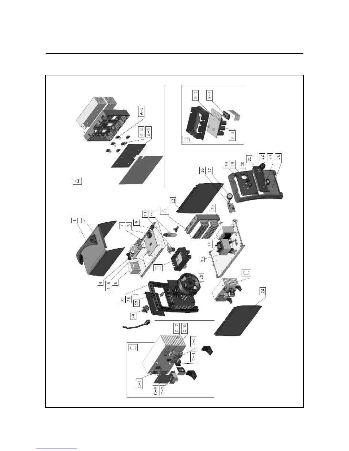
Spare Parts - 1
17

Spare Parts - 2
82U8253035
82U8301647
82U7202123
82U5496908-B
82U6271799
82U7731266-E
82U5496903-D
82U7624270
82U8462106
82U7253009-B
82U7253400
82U8050647
82U6185634
82U6271634
82U5496204
82U5496907-B
82U7304050
82U8306647
82U7227017
82U7458009
82U8065647
82U7667001
82U7152316
82U8051647
82U8068004-B
82U8307008
82U8462634
82U7720030
82U7232020
82U8069004
82U5422002
82U7425641
82U7231275
82U5496906-B
82U5496670-H
82U7411311
82U7461215-B
1
2
3
4
5
6
7
8
9
10
11
12
13
14
15
16
17
18
19
20
21
22
23
24
25
26
27
28
29
30
A PART
A
A--1
A--2
A--3
B PART
B--1
B--2
B--3
Part Number Part Description
No.
Handle
Machine Cover
Fuse
EMC PCB
EMC Inductance (Sold Separately)
Auxiliary Transformer
Control PCB
Fitting
Connection-Peg
Solenoid Valve
Pressure Regulator
Left Side Panel
Main Transformer
Inductance
HF Absorb PCB
Front Control PCB (Plasma)
Pressure Meter
Front Control PCB Asbly
Panel (Plasma)
Selecting Switch Knob
Output Terminal Panel (Plasma)
Center Socket
Output Socket (10-25)
Right Side Panel
Plastic Rear Panel
Rear Panel Asbly Plate
Gas Inlet Connector
Fan
Switch
Plastic Front Panel
Inverter PCB module (w/IGBT)
IGBT (Inverter PCB)
Thermal Switch
Inverter PCB (w/o IGBT)
Rectifier PCB
Rectifier Bridge
Electrolytic Capacitor
Amount
1
1
1
1
1
1
1
2
1
1
1
1
1
1
1
1
1
1
1
1
1
1
1
1
2
1
1
1
1
1
1
6
2
1
1
2
6
18

Spare Parts - 3
82U7425634
82U5496902-D
82U7321101
82U8751060
82U5496904-B
82U7421540
82U7445321
C PART
C--1
C--2
C--3
C--4
C--5
C--6
C--7
No.
IGBT (Pilot Arc)
Pilot Arc PCB
Hall Sensor
Mur Spacing Block
Mur PCB (Plasma)
Fast Recovery Diode (Plasma)
Output Resistance
2
1
2
1
1
1
2
Part Number Part Description Amount
19
Table of contents
Popular Cutter manuals by other brands

Makita
Makita 4112HS instruction manual

Weber Rescue Systems
Weber Rescue Systems SPS 270 MK2 E-FORCE3 operating manual

Sparta
Sparta Huskie TOOLS REC-630Y Operation manual

FLORABEST
FLORABEST PRC 9.6 Operation and safety notes

Powerline
Powerline PL2620 Installation, operating and maintenance instructions

Far Tools
Far Tools BTC 180 manual


