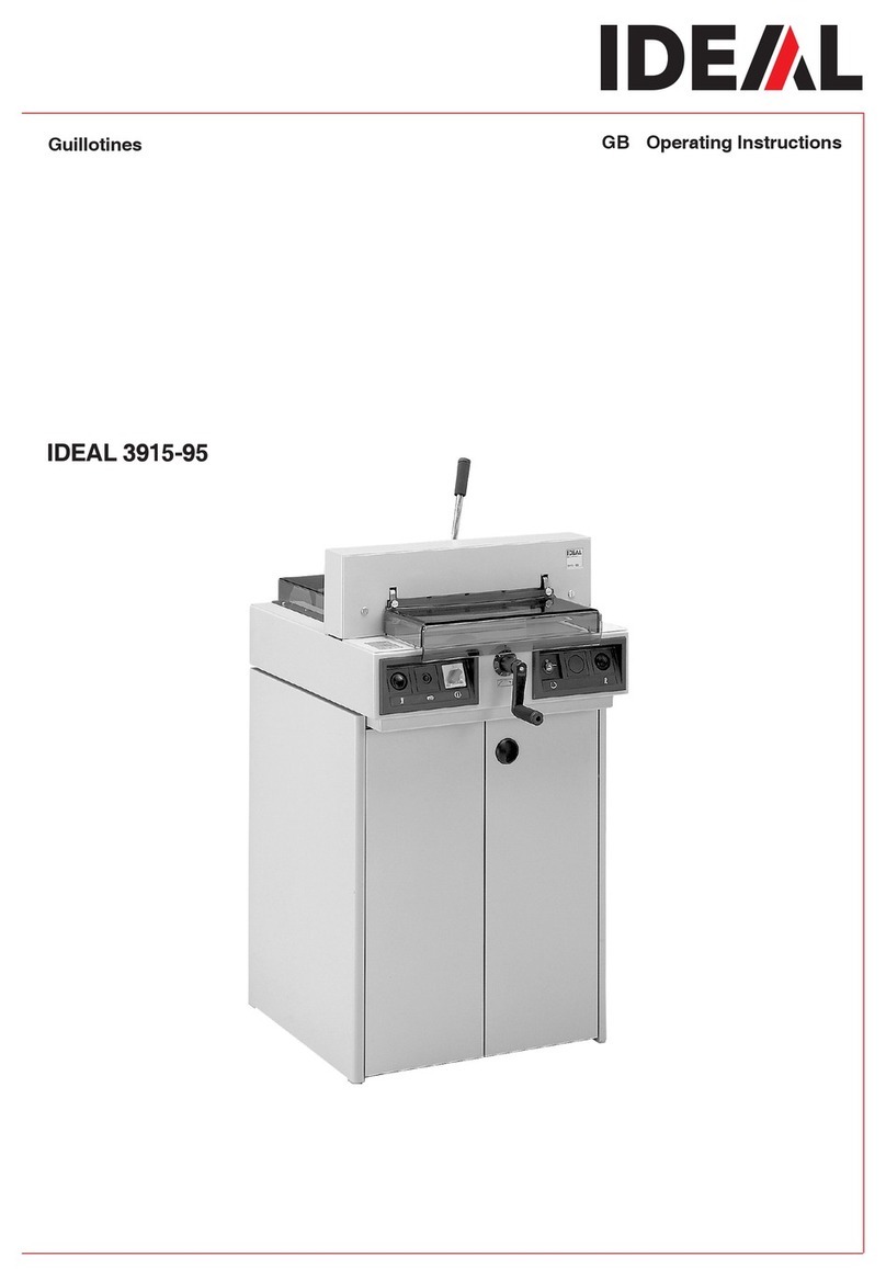
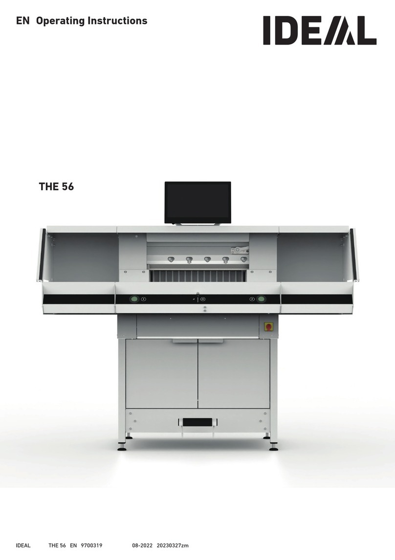
IDEAL THE 56 User manual

THE 56
EN Operating Instructions

2
Table of Contents
Safety Precautions 3
Intended Use 6
Overview and Parts Designation 7
Scope of Delivery / Options 8
Setting Up 9
Commissioning 10
Operating 11
Operating / Multi-Touch Display 13
Blade Change 22
Changing the Cutting Stick 28
Maintenance and Upkeep 29
Yearly Maintenance / Safety Inspection 30
Multi-Touch Display Settings 31
Possible Malfunctions Multi-Touch Display 33
Possible Malfunctions Cutting Machine 34
Accessories / Options 35
Technical Data 36
EC Declaration of Conformity 39

3
Safety precautions
Please read these operating instructions before putting the machine into
operation and observe the safety precautions.
The operating instructions must always be available.
Children must not operate the machine!
Do not reach beneath the blade!
Never leave the blade unattended! Do not extract
or transport the blade without protection! (See page 24).
Danger! Risk of injury!
Do not cut hard materials or materials which may splinter!
Do not use any spray cans with flammable content near to the cutting machine!
Do not use any flammable cleaning agents.
Blade must always be covered by the pressing bar.
This machine is constructed for „one-man operation“ only!

4
Safety Precautions
Safety precautions - Multi-touch display
• The multi-touch display is firmly fitted to the machine.
• Never expose this multi-touch display to rain or moisture to prevent any fire or
electric shock risk. Dangerous high voltages are present inside the multi-touch
display. Do not for this reason open the housing. Only have qualified persons
undertake repairs.
• Do not expose the monitor to an excessive amount of dust.
• Never spray cleaning agents directly onto the monitor.
• Slots and apertures at the front and back of the housing are for ventilation.
Make sure these openings are never blocked or covered to ensure reliable
operation of the multi-touch display and to protect it from overheating.
• Do not align or set up any heat sources facing the multi-touch display.
• Do not insert any items into the slots of the monitor housing. Otherwise
short-circuits might develop producing a fire or electric shocks. Never spill
liquids onto the monitor.
• Do not yourself attempt to service or repair the multi-touch display. You could
subject yourself to dangerous voltages and other hazards by opening or
removing the covers.
• Leave any maintenance or repair work to qualified specialists.
Particular features of LCD monitors
The following symptoms are quite normal for LCD monitors and do not point to
any particular problem.
• The fluorescent light may cause the screen to flicker when used for the first
time. Press the main switch o (wait for 30s) and then back on to check that
the flickering on the device has disappeared.
• Depending on the desktop design you use, you might detect a minor degree of
uneven brightness on the screen.
• The LCD screen has at least 99.99% eective pixels.
In the case of 0.01% of the pixels or less, they might either never be shown or
shown constantly.
• An LCD screen characteristic is that on image change-over an after-image of
the previous screen is retained should it have been shown for several hours. In
such an instance, the screen is slowly restored either from alternating images
or by a device switch-o for several hours.
• In the event of the screen suddenly flickering or the background light failing,
then contact your dealer for the matter to be repaired. Do not yourself attempt
to repair the monitor.

5
1
1
1
2
1
1
2
Safety Precautions
Disconnect the mains plug prior to servicing
and when removing any panels.
Protect the power cable
1
from heat, oil and
sharp edges!
The machines are default-delivered with the
following setting:
• Voltage 230 V (120 V) 1 ph.
• Frequency 50 Hz (60Hz).
Dangerous machine parts are protected
by guards and covered by panels
1
. The
machine may only be operated with all safety
and panelling sections fitted and in particular
with:
• Safety light beam curtain
2
• Screwed down panels
1
Caution! Avoid any rapid machine
switching on and o.
Wait for at least 30 seconds until the control
unit has fully run down.
The dangerous cutting movement is protected
by a safety light beam curtain
1
and a two-
hand cutting
2
activation!

6
Safety Precautions / Intended Use
Shut down if not in use for a long period.
(Main switch to “0”).
Intended use
This machine is for cutting stacks of paper to
acertain size.
Safety Precautions
This machine is only for
a“One-man operation”!
Caution! Any staples and the like damage
the cutting blade.

7
1
7
8
11
3
10
9
4
2
6
5
17
12 151413
20
19 18
16
Overview and Parts Designation
1
Paint brush (in the tool kit as delivered)
2
Blade
3
Back gauge
4
Cutting stick
5
Test rod for the safety light beam curtain
(in the tool kit as delivered)
6
Front table
7
Two-hand cutting activation
(operating buttons)
8
Operating control for electrical back gauge
adjustment
9
Main switch (lockable)
10
Tool panel (tool kit)
11
Adjustable foot
12
Belt cover
13
Rear table cover
14
Light beam curtain holder
15
Cover
16
Multi-touch display
17
Safety light beam curtain
18
Mechanical foot pressing
19
Base frame
20
Rear table

8
12
3
4
1
2
Scope of Delivery / Options
Options Set of side tables
1
Order No. 9000 552
(The add-on instructions are enclosed with
the side tables.)
Base frame panelling
2
Order No. 9000 553
(The add-on instructions are enclosed with
the base frame panel.)
1
Cutting machine
2
Multi-touch display incl. 4GB USB stick
Note! Do not withdraw USB stick during an
ongoing operation!
3
Paper knock-up block
4
Tool panel:
• Blade changing device
• Clamp bar cover
• Tool kit
• Operating instructions
Scope of delivery

9
2
1
55°
0°
Setting Up
The adjustable feet
2
are used to level the
machine and eect height adjustments:
• Level machine with spirit level, 4x adjustable
feet
2
AF17.
• Reference face machine table
1
.
Caution! Disconnect mains plug before
assembling the display.
• Insert display into the slots as far down as
possible.
• Bring the pivoted display to the position
required. The display angle is adjustable from
0° to 55°.
• Tighten with cam lever.
Note: The clamping force is readjustable.
Release cam lever and hold, turn the swivel
axis, tighten cam lever.
• Carefully insert display flat cable into the
appropriate machine socket.
• Screw down the cover with 2 screws.

10
2
1
1
2
STOPSTOP
5
4
3
Plug in power cable
1
at the power socket.
Main switch
2
at Position “I” .
The reference point for the back gauge is
automatically moved to.
The machine is operational.
Commissioning
The machine may only be operated when
the operating instructions and the safety
precautions have been understood.
Before each use, check the safety equipment
for completeness and functionality.
• All panels
1
must be attached.
• Light beam curtain
2
must be fitted.
• The cut may only be activated simultaneously
with the two-hand activation of the operating
buttons
5
.
• Light beam curtain:
Holding the test rod
4
(tool kit) in the
protective field
3
is to result in the
immediate stoppage of an activated cycle.
It is recommended keeping a test handbook.
Caution! Avoid any rapid machine
switching on and o.
Wait for at least 30 seconds until the control
unit has fully run down.

11
21
21
3
3
1 2
The dimension is set manually by way of the
operating control for the electrical
back gauge adjustment
2
or by way of
programming the cutting size at the multi-touch
display
1
.
Operating
Cutting line indicator - optical:
Cut shown by optical red light beam
1
, blade
cut at the front edge of the light beam.
Cutting line indicator - mechanical:
For marking-based cutting, the clamp bar
2
can be used as the cutting line indicator (the
cut occurs approx. 1 mm before this). The foot
pedal
3
allows the clamp bar to be brought
into any position.
Paper installation at the back gauge
1
and
side stop to the left and right
2
. Use the
provided paper knock-up block
3
for
adjusting paper stacks.
(Move back gauge forwards before turning
the stack of paper).

12
2
1
2
1
3
2
Clamp bar cover:
To prevent clamp bar pressure marks on
sensitive materials, a clamp bar cover
1
is
provided (tool panel).
Dismantling:
• Remove clamp bar cover
1
downwards by
hand or gently press into the recess using
the provided spanner ( in the tool kit).
The narrow cut is 15 mm.
Assembly:
• Clip the clamp bar cover
1
upwards into
the clamp bar
2
.
(for status indicator see Page 15)
The narrow cut is 60 mm.
Operating
Cutting activation / Clamping
Caution!
Never reach into the cutting area when the blade
is in motion.
Only when the specified dimension is moved to
can a cut be activated.
• Release the light beam curtain protective area
1
.
• Simultaneously press both operating buttons
2
of the two-hand activation system and keep
pressed until end of the cut.
• Clamping is done automatically by actuating
the operating buttons
2
before cutting. The
paper can also be pre-pressed beforehand
with the foot pedal
3
.
• Move back gauge forwards before turning the
stack of paper.
• Blade must always be at the top and covered
by the clamp, do not touch the blade (see Page 26).
Injury risk.
Termination of cutting
Release both operating buttons
2
of the
two-hand activation system.

13
2
1
Operating / Multi-Touch Display
Starting machine
• Main switch
2
at Position “I”, the reference
point for the back gauge is automatically
moved to (operating buttons
1
light up
yellow). After a complete start 56.00 cm is
shown on the display, the operating buttons
light up green.
The cutting machine is operational.
Note:
Does the screen stay dark?
( see Page 33 “Possible malfunctions”)
You are in the “home” mode .
Note: The left-hand side of the multi-touch
display is the interactive side. The green
symbols indicate the mode.
Setting the clamping pressure (general)
Tap on symbol , set clamping pressure from
1
to
8
and save with (shown with an
exponent next to the symbol
8
).
Table lighting
Tap on symbol , set from
0
= table lighting
o, up to
100
and save with .
Cutting line indicator
Tap on symbol , set from
0
= cutting line
indicator o to
100
and save with .
Button sound
Tap on symbol , set from
0
= button sound
o up to
100
and save with .
home - mode
The unit of measurement can be changed by
tapping in the dimension indicator on
cm
and
also either in
mm
or
inch
.
Caution! Avoid any rapid machine
switching on and o.
Wait for at least 30 seconds until the control
unit has fully run down.

14
4
1 2
5
3
Marking-based cutting
• By pressing operating control
5
upwards,
move back gauge to the rear.
• Insert the paper and slide it using the paper
knock-up block
4
to the back gauge
1
and
side stop
2
to the left and right.
• Press operating control
5
downwards until
the marking on the item to be cut is under the
optical cutting line indicator
3
.
• The further the operating control
5
is
pressed downwards, the quicker the back
gauge
1
moves to the front.
Moving the back gauge to the rear is only
possible in the rapid mode by pressing the
operating control
5
upwards.
Cutting to a specified dimension
• Enter dimension in the numeric keypad.
Dimension appears in red (an incorrectly
entered dimension can be cleared by
tapping
C
).
•
START
- tap on.
Dimension is moved to and again appears in
white after reaching the required position.
• Insert the paper and slide it using the paper
knock-up block
4
to the back gauge
1
and
side stop
2
to the left and right.
• Activate the cut.
RAPID SELECTION cutting
DIN and readily programmable dimensions can
be called up from the respective symbols. DIN
A2, A3, A4, A5, A6, A7, B3 und B4 or 4¼”, 5½”, 7”,
8½”, 11”, 12”, 14” and 17” (
inch
) are saved.
•
+
Tap on to program the next available
RAPID SELECTION. Enter the dimension and
save with .
• To change RAPID SELECION dimensions,
press the corresponding dimension and keep
pressed, then to .
• To clear RAPID SELECION dimensions, press
the corresponding dimension and keep
pressed, then to .
home - mode
Operating / Multi-Touch Display

15
1Consecutive dimensioning function
• Enter start dimension in the numeric keypad.
• Start entered dimension with
START
.
• Slide paper to back gauge
1
.
• Tap on the consecutive dimensioning symbol
.
• Enter consecutive dimension and save with
• Consecutive dimension symbol lights up in
green . The entered consecutive
dimension is shown under symbol
2.00cm
.
• Activate cut.
The back gauge
1
travels forwards around
the inputted consecutive dimension.
• This operation is repeated after every cut
activation.
Eject function with target dimension
• Tap in target dimension and start with
instead of
START
.
The back gauge starts o forwards for paper
removal, the entered target dimension is
then automatically moved to. (function only
with travel to the rear).
Pocket calculator function
• Calculate the required dimension, e.g.
40 - 2 = 38, then
START
or instead of
=
immediately tap on
START
, the calculated
38 dimension is immediately moved to.
Note: This function can also be used in the
PROGRAM MODE.
home - mode
Operating / Multi-Touch Display
Ending the consecutive dimension function
• Tap on the consecutive dimensioning symbol
2.00cm
. The symbol is again highlighted in grey
and the consecutive dimension extinguished
.
Clamp bar cover (status indication)
• An installed clamp bar cover is shown by the
symbol in the numeric keypad.
Eject function
• Press symbol
The back gauge travels forwards around the
pre-eject dimension to paper removal and
then back to the initial dimension.

16
5
Creating a program
You are in the “home” mode .
• Tap on symbol , select appropriate
folder, designate program and open with .
Create program step
• Tap on symbol .
• Tap on dimension, enter start dimension e.g.
50.00 cm accept with , with the step is
then incorporated into the program.
home - mode PROGRAM MODE
Operating / Multi-Touch Display
• You switch to the PROGRAM MODE.
The program name appears.
• By tapping on you can edit the program
name at any time.
Dimensions can also be moved to for
acceptance in one step:
• Move to cutting marks with the operating
control
5
, using symbol accept the
dimension moved to in the program step and
with incorporate into the program.
Incorporating program step
With symbol a fresh step can, for instance,
be incorporated ahead of selected Step 2 or
directly behind using the symbol.

17
Turn sheet (information for users)
• Put hook at “Turn sheet” and select one of
four variants.
Swipe upwards.
Set clamping pressure
• Place hook at “Clamping pressure” and set
from 1 to 10. Swipe upwards.
Set advance speed of the back gauge
• Place hook at “Speed”, set from 1 to 10
(generally 10 is the highest step set). Swipe
upwards.
Eject function
• Place hook at “Eject”
(automatically goes to ) when you want
the paper stack to be ejected.
Note: Cannot be selected simultaneously with
the consecutive cut function.
Consecutive cut
• Put tick at “Consecutive cut”, tap the
dimension and enter accordingly, determine
number of the steps with
+
and
-
.
Note: Cannot be selected simultaneously with
the eject function.
Swipe upwards to enter more options.
Editing program step
Following inputs are possible in a program step:
PROGRAM MODE
Saving program step
• Accept program step with when all the
required features are set.
Program step is shown with the inputted
features.
Call up next step .
Operating / Multi-Touch Display

18
Clearing program step
• Program step by going upwards / downwards
Select swipe and tap on .
Select program step
• Program step by going upwards / downwards
Select swipe and directly tap on.
Save program
• Save program with the symbol.
Call up saved program
• Open file manager, tap on to select
required program, a double tap to open it.
• Tapping on the symbol changes a program
to the favourite and is shown immediately
in the “home” mode (as rapid access).
• Tapping on the 3 dots in the favourite box
opens up a text box where you can freely enter
a text and save it.
Program start
• Program is called up. Tap on the symbol
to start the program. The first program step is
moved to.
TheActivate cut. The second step is moved to
etc. On carrying out the last step, tap on the
symbol to restart the program.
Processing, interrupting and stopping program
• Tap on the symbol to run down a program
without cutting. Individual steps can also be
selected by swiping upwards / downwards and
directly started by tapping the symbol.
• Tap on the symbol to interrupt the
program. Tapping on the symbol rescinds
the active pause.
• Tap on the symbol to stop. You can then
re-start the program from the beginning by
tapping.
PROGRAM MODE
Operating / Multi-Touch Display

19
Create and organize folder
• Open the file manager with the symbol
Top folder “home” is displayed. This folder
cannot be renamed or deleted.
• Tap the symbol, name the folder and create
it with .
Note: In this way a sub-folder can be generated
in any additional folder.
• The symbol permits the selected folder to
be re-named and cleared with .
Note: Although the top-most folder can be
re-named in the PROGRAM MODE it cannot be
cleared.
• Tapping on the symbol shows up or
conceals a folder’s content.
Create, replicate and move programs
• The symbol permits a program
P
to be
created in the selected folder.
• To replicate a program, select it, tap on ,
name program and with save with .
• To move a program, select it, tap on , select
the folder where the program is to be moved to,
select and save with .
Searching in the FILE MANAGER
• The search function is limited to the word
search in the FILE MANAGER mode.
FILE MANAGER
Operating / Multi-Touch Display

20
SETTINGS
In general
Date / time
• With the symbol open the appropriate
heading. Set by swiping upwards/ downwards
and save with .
Eject dimension (cm)
• With open the appropriate column. Tap in
the eject dimension (max. 15.00 cm) and save
with .
Set / change user PIN
• With open the appropriate column.
Tap in PIN (min. 4-digit / max.10-digit) twice
and save with . Unlocks the standby mode
and screen lock ( On / O button). If no PIN
is set, then 1234 unlocks the PIN (as-delivered
state).
Cutting button brightness
• With , activate appropriate column for
changing. Set by swiping to the left /right and
with save with .
Standby mode after (min.)
• With open the appropriate column.
Tap in SLEEP TIMER (max. 120 min.) and save
with . Standby mode is displayed by a “zZ
Symbol” next to the operating control.
Unlock with the user PIN.
Blade change information
• With open the appropriate column.
Tap in BLADE CHANGE WARNING LIMIT (max.
500,000 cuts) and save with .
• Under an activated application (>1), a
coloured bar indicates how many cuts could
still be carried out before replacing the blade
(an extra pointer pops up).
• Input value 0 deactivates this application.
Operating / Multi-Touch Display
Other manuals for THE 56
1
Table of contents
Other IDEAL Cutter manuals