Because there are large differences between PC’s, we can give you only a general
installation guide for the EX-3605 Please refer your computer’s reference manual
whenever in doubt
1 Turn off the power from your computer and any other connected peripheral
2 Remove the mounting screws located at the rear and/or sides panels of your Com-
puter case and gently slide the cover off
3 Locate an available 2 5-inch expansion Slot
4 Align the EX-3605 with the expansion Slot, and then gently but firmly, insert the
converter Now fix the EX-3605 with the 4 screws which is in the extend of delivery
5 Connect the SATA cable to the SATA connector at the EX-3605 and then connect
the other end of the SATA cable to your mainboard or SATA controller
6 Gently replace your computer’s cover and the mounting screws
651
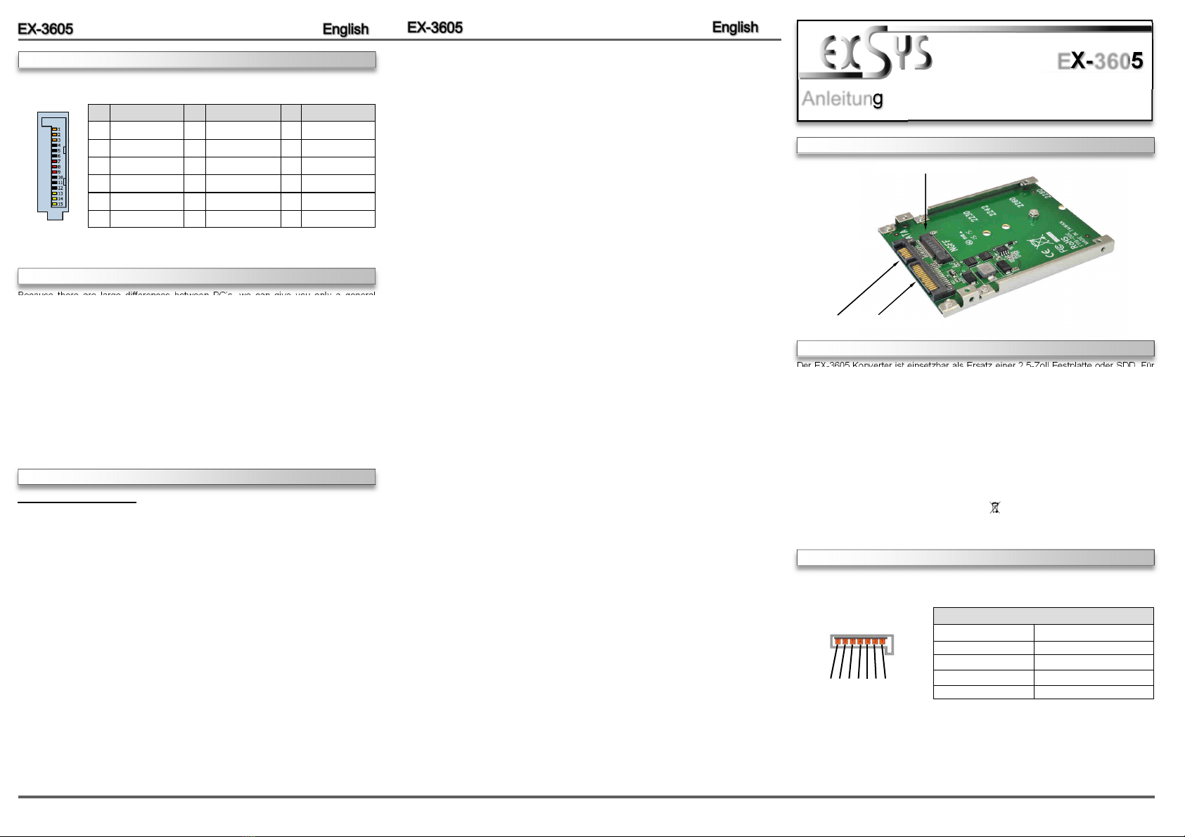
ANSCHLÜSSE
Der EX-3605 Konverter ist einsetzbar als Ersatz einer 2 5-Zoll Festplatte oder SDD Für
den Anschluss der EX-3605 wird ein SATA Anschluss auf dem Mother-Board oder
einem SATA Controller benötigt Die Module M 2 NGFF 2280, 2260 und 2242 können
eingesetzt werden Es werden Module unterstützt mit B-Key sowie auch B+M Key Die
EX-3605 gewährleistet eine sichere Datenübertragung bis zu 6GB/s! Es ist nicht mög-
lich die I/O Adressen und Interrupts manuell einzustellen, da die Einstellungen des
Konverter vom System (BIOS) und beim installieren des Betriebssystems automatisch
vorgenommen werden
BESCHREIBUNG & TECHNISCHE DATEN
AUFBAU
Kompatibilität: M 2 NGFF & SATA
Betriebssysteme: Alle Betriebssysteme
Anschlüsse: 1x 22 Pin SATA und Power, 1x 67 Pin M 2 NGFF
Lieferumfang: EX-3605, 4 Befestigungsschrauben für 2.5“ Rahmen,
Befestigungsschraube für M.2 Module, Anleitung
Zertifikate: CE / FCC / RoHS / WEEE DE97424562 / WHQL
22 Pin SATA und Power Anschluss
Anleitung
Vers 1 0 / 02 12 16
EX-3605
HARDWARE INSTALLATION
DRIVER INSTALLATION
All Operating systems
After the hardware installation, the operating system will recognize the device automati-
cally and install the drivers
Slot für M 2 NGFF Modul
SATA (Daten):
7 6 5 4 3 2
SATA Anschluss
Pin Signal Pin Signal
1GND 5B- (Empfangsrichtung)
2A+ (Senderichtung) 6B+ (Empfangsrichtung)
3A- (Senderichtung) 7GND
4GND
CONNECTORS
Pin Assignment Pin Assignment
13 3 Volt (Orange) 7 5 Volt (pre-charge)
23 3 Volt (Orange) 85 Volt (Red)
33 3 Volt (pre-charge) 95 Volt (Red)
Pin Assignment
13 12 Volt (pre-charge)
14 12 Volt (Yellow)
15 12 Volt (Yellow)
4Ground (Black) 10 Ground (Black)
5Ground (Black) 11 Reserved
6Ground (Black) 12 Ground (Black)
SATA (Power):


