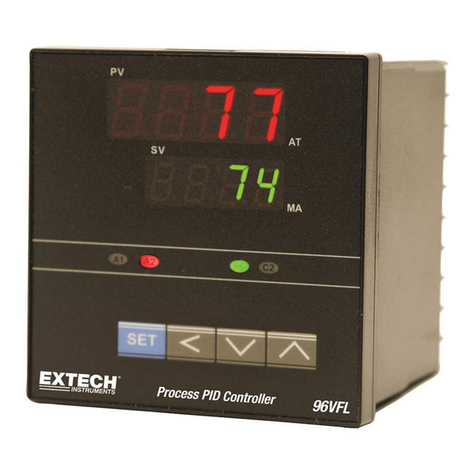
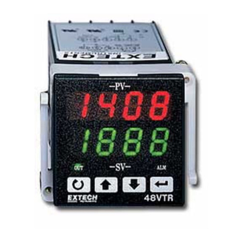
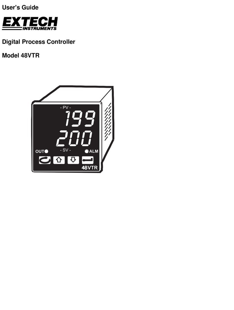
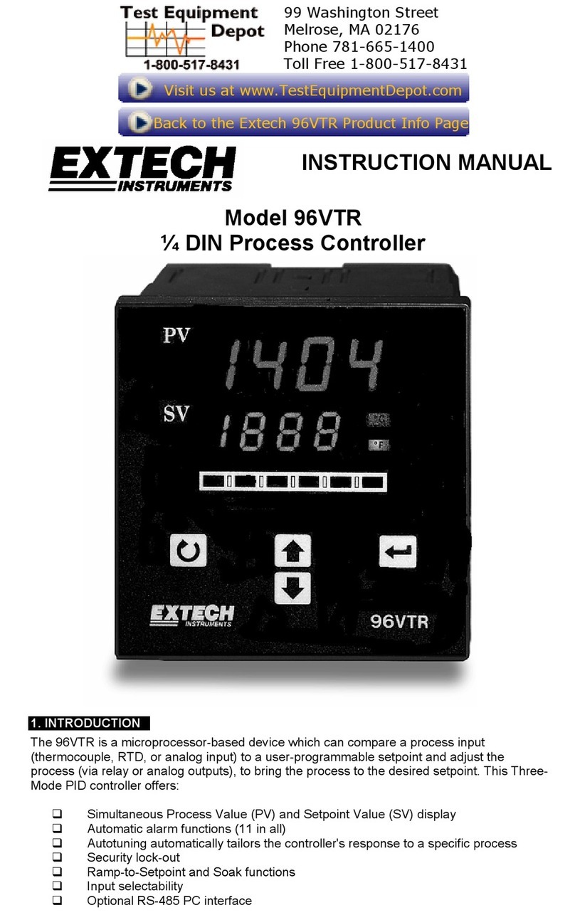
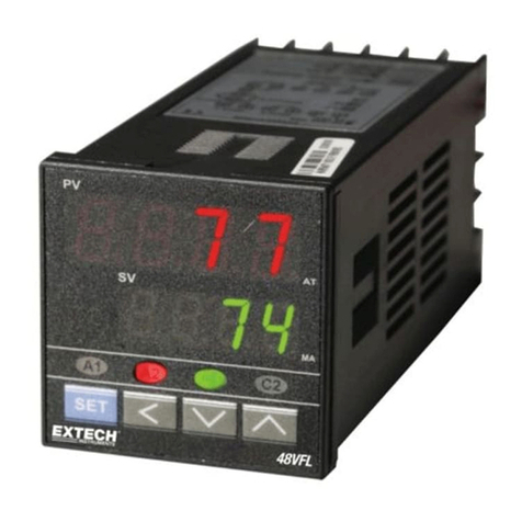
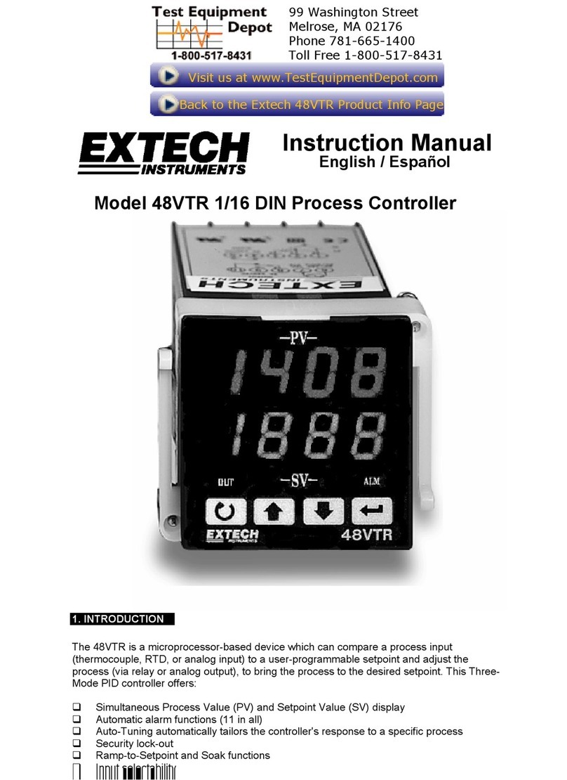
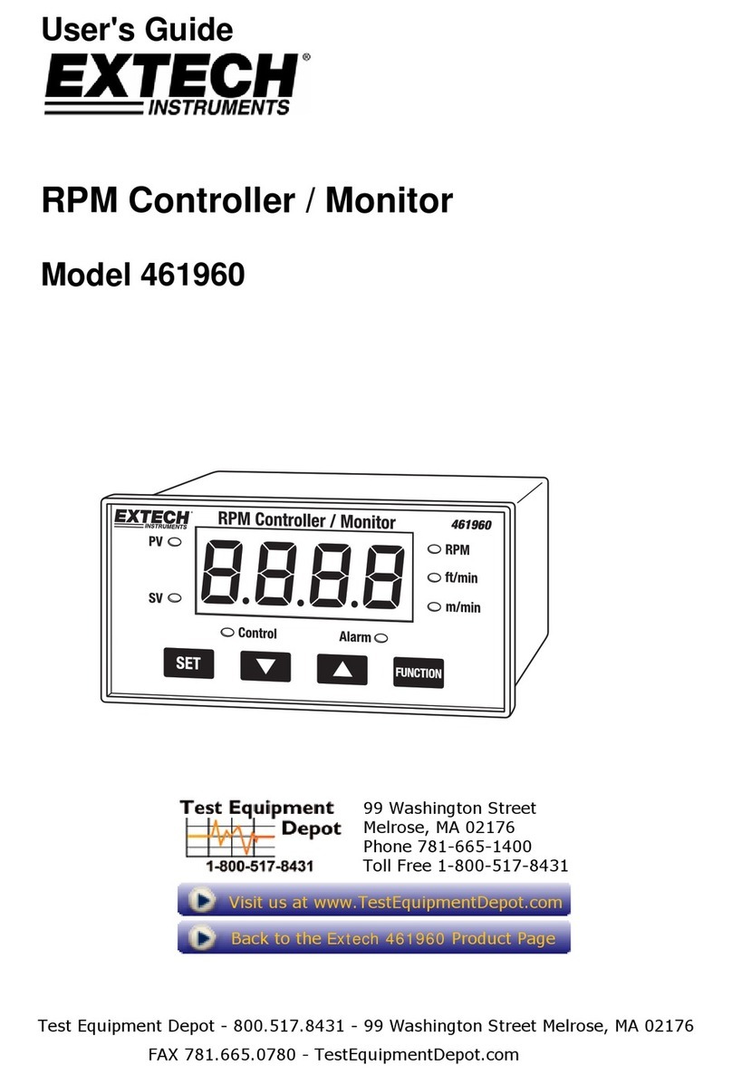
Extech Instruments 48VTR User manual

USER MANUAL
Digital Process PID Controller
Model 48VTR

48VTR User Manual v6.0 10/1/20
2
Contents
Introduction ...................................................................................................................3
Mounting .......................................................................................................................4
Wiring ............................................................................................................................4
Front Panel Description..................................................................................................6
Keypad Descriptions.......................................................................................................6
Display Descriptions .......................................................................................................7
Process Control Preparation ..........................................................................................8
Process Control Operation .............................................................................................8
First Programming Menu Level....................................................................................12
Second Programming Menu Level ...............................................................................13
Third Programming Menu Level...................................................................................14
Fourth Programming Menu Level ................................................................................16
Automatic Tuning.........................................................................................................17
Automatic and Manual Control Modes........................................................................18
Ramp-to-Setpoint Limit................................................................................................18
Soak and Event Timers .................................................................................................19
Appendix A: Alarm and Timer Functions......................................................................21
Appendix B: Heating Application Example...................................................................23
Calibration....................................................................................................................24
Specifications ...............................................................................................................25
Two-year Warranty......................................................................................................28
Calibration and Repair Services....................................................................................28
Contact Customer Support ...........................................................................................28

48VTR User Manual v6.0 10/1/20
3
Introduction
Thank you for selecting the Extech 48VTR Process Controller. The 48VTR uses intelligent
algorithms (including fuzzy logic) to offer highly precise process control. The wide array of
features and functions are easily configured in the four program menu levels.
Controller Wiring
The controller must be wired before use. Inputs, outputs, and AC power are connected on the
rear terminals as described in the Wiring section.
Process Inputs
The 48VTR can be ordered in a variety of input configurations. For temperature versions, the
controller accepts a thermocouple or RTD thermometer. For analog versions, the controller
accepts a 4 to 20mA process signal.
PV (Process Variable) Display
Process inputs values are displayed on the PV (Process Variable) digits on the front panel.
Control Outputs
The 48VTR offers three control output options: Mechanical relay, Pulsed DC Trigger (29VDC),
and Analog (4-20mA). Relay and Trigger outputs are ON-OFF control types (pulsed). The 4-20
output, on the other hand, is a linear signal corresponding to 0 to 100% output power.
Alarm Output
The Alarm relay can be used to perform a variety of alarm and timer functions. Alarms can be
used to shut down power in the event of an emergency, switch on an alert signal, control other
variables in a process, and more.
Setting Value (SV)
The Setting Value (SV), also known as the Setpoint, is the target point for your process. The SV
is changed using the arrow keys. The SV is displayed on the lower LED digits in green.
Programming Menus
The controller has four Programming Menu Levels. Each menu includes a series of
customizable control and tuning parameters.
Tuning the Controller
The controller’s PID settings must be tuned for each application. Run the Auto Tune utility
after the controller is wired and ready for use. Manual tuning adjustments can also be made.
Tuning is key to a stable process.
Contact Extech
Visit the Extech website www.extech.com for customer support, up-to-date user
documentation, and full warranty information. This device is covered by a 2-year limited
warranty.

48VTR User Manual v6.0 10/1/20
4
Mounting
1. Prepare a panel cutout to these specifications: 1.77 x 1.77" ± 0.02" (45 x 45 mm ± 0.5
mm); Panel thickness: 0.4" (10mm) max.
2. Remove the plastic mounting bracket and slide the controller into the panel, through the
cutout.
3. Replace the mounting bracket and tighten the bracket screws. Do not over tighten.
Wiring
AC Power Wiring
Terminals 6 and 7 can safely accept 90 to 264VAC 50/60Hz.
Thermocouple Input
Terminal 1 (-) and terminal 2 (+).
Analog Input (4-20mA)
Terminal 1 (-) and terminal 2 (+).
RTD Input (2, 3, or 4 wire)
Refer to the diagrams below.

48VTR User Manual v6.0 10/1/20
5
Control Relay Wiring
Terminals 8, 9, and 10 are used for the control relay. Terminals 8 and 9 are used as a normally
open switch; terminals 8 and 10 are used as a normally closed switch.
When the controller activates the relay, the normally open switch closes and the normally
closed switch opens.
The relay itself does not provide power. AC power must be wired as shown below.
Pulsed DC Trigger Output Wiring
The DC Trigger output delivers 29V DC (approx.) from terminals 8 (positive) and 9
(negative).
Analog Output Wiring
The 4 to 20mA DC output is available on terminals 8 (+) and 9 (-). Parameter ‘Ct’(in the 3rd
Program Menu) must be set to ‘0’ when using an analog output.
Alarm Relay Output
The Alarm Relay is a normally open (N.O.) switch available at terminals 4 and 5. Power
must be supplied as shown below.

48VTR User Manual v6.0 10/1/20
6
Front Panel Description
1. Process Variable (PV) display digits
(red) show the process input.
Rightmost decimal flashes when
controller is Auto Tuning. Program
menu items are also displayed here.
2. Setting Variable (SV) display digits
(green) show the process setpoint.
Programming menu items are also
displayed here.
3. Control Output (OUT) status LED:
Switches ON when the output is ON.
4. Scroll button for navigating menus
and other control functions.
5. Up arrow key for navigating menus and changing settings.
6. Down arrow key for navigating menus and changing settings.
7. Return button for exiting menus and other control functions.
8. Alarm Output (ALM) status LED: Switches ON when an alarm is triggered; it also blinks
when the Alarm Timer is running (see Event and Soak Timer section).
Keypad Descriptions
SCROLL KEY
•Press once to access the 1st Menu and press again to navigate the menu parameters.
•Hold the Scroll and Return keys for 5 seconds to change the menu level. The red LED
display shows the current selection.
•Hold the Scroll key for 5 seconds to start an Auto Tuning session.
AROWS KEYS
The arrow keys are used to adjust the Setting Variable (SV) and for navigating/changing
settings in the four programming menu levels.
RETURN KEY
•Press to view the controller output level as a percentage (0.0 to 100.0%).
•Press and hold for 5 seconds to activate Manual Control (see the Automatic and Manual
Control section).
•Press key from any other mode to return to the normal SV display.
•Hold the Return and Scroll keys for 5 seconds to jump to another programming menu level.

48VTR User Manual v6.0 10/1/20
7
Display Descriptions
Process Variable (PV) Display
•During normal operation, the top LED (red digits) displays the actual process
measurement variable (PV).
•When you access one of the four programming levels, the red LED digits display the
currently selected parameter.
•The red LED digits also display error messages.
Setpoint Variable (SV) Display
•During normal operation, the bottom LED (green) displays the Setting Variable (SV). This is
the desired process point, use the arrow keys to adjust.
•The Setpoint cannot be adjusted higher or lower than the High and Low Limit parameters
(3rd Menu Level).
•In program menus, the green LED digits show the setting for the selected parameter
(shown on the red LED digits).
Display Status Indicators
'ALM' Relay Status LED
This red LED is lit when the Alarm relay is active. It flashes when the Alarm is configured
as an Event/Soak Timer and the timer is running. Refer to the Soak and Event Timers
section and the Appendices.
'OUT' Status LED
This green LED switches on/off as the control output switches on/off.
AUTO TUNE Status Indicator
When the controller is Auto Tuning, the rightmost decimal point on the PV display flashes.
The decimal will stop flashing when Auto Tune is finished.
PV Display Error Messages:
AdEr:A/D converter problem. Unit must be repaired or replaced.
Flashing PV: Measured input exceeds the limits of the controller.
OPEN: No sensor connected or sensor inoperable.

48VTR User Manual v6.0 10/1/20
8
Process Control Preparation
Connect the Inputs
The input types (thermocouple, RTD, analog) are hardware dependent. The part number
ordered, and the product label indicate the input type. If you are uncertain, please contact
Extech. Wire the input as described in the Wiring section.
Connect the Outputs
The output types (relay, dc trigger, analog) are hardware dependent. The part number
ordered, and the product label indicate the output type. If you are uncertain, please contact
Extech. Wire the output as described in the Wiring section.
Program the Controller
The four programming menus contain critical settings that can optimize the control of your
process. Success depends largely on configuring and tuning the controller correctly. Refer to
the Programming Menu and Process Control Operation sections for details.
Process Control Operation
Relay Output Control
The control relay is a mechanical, single-pole/double-throw, form C contact, and, by definition,
can only be in one of two states, ON or OFF. Control relays are wired in series with the control
equipment (heater, pump, etc.) and requires AC power to operate. The ON-OFF and Time
Proportioning control methods, explained below, apply to Relay output control.
Pulsed DC Trigger Option
The DC trigger supplies a 29V pulse from terminals 8 and 9 and is an ON-OFF control type. The
ON-OFF and Time Proportioning control methods, explained below, apply to DC Trigger
control. Caution: With DC trigger installed do not connect AC voltage to terminals 8 or 9.
Analog Output Option
With the analog output option, terminals 8 (+) and 9 (-) supply 4 to 20mA to the process. The
controller regulates the output to bring the process (PV) to setpoint (SV).
Unlike ON-OFF and Time Proportioning control, the 4 to 20 signal is a linear output where the
0 to 100% output variations regulate the 4 to 20mA signal (0% power = 4ma, 50% power =
12ma, 100% = 20mA, and so on).
To use the analog output, ensure that ‘Cycle Time’(‘Ct’in the 3rd Menu Level) is set to ‘0’
Using ON-OFF Control
ON-OFF is the simplest form of control, where the controller output is OFF at setpoint and ON
away from setpoint. To use ON-OFF control, set ‘Pb’ (2nd Menu) to ‘0’. Use the Hysteresis
setting (‘Hyst’in the 3rd Menu) to create a ‘dead band’around the setpoint to minimize relay
chatter.
48VTR User Manual v6.0 10/1/20
9
Time Proportioning Control
To overcome the limitations of ON-OFF control (setpoint overshoot, wide process oscillations,
‘droop’, etc.), Time Proportioning can be used.
Time Proportioning control is active when Proportional Band ‘Pb’(2nd Menu) is set to any value
other than ‘0’. Proportional Band is a key tuning parameter as discussed below.
When Time Proportioning is active, the controller ‘throttles’the output relay, keeping the
relay on for longer periods when the PV is far from SV, and vice versa. The ratio of output ON
time to output OFF time is automatically adjusted for each ‘Cycle Time’.
At the start of each time cycle, the controller re-adjusts the % output, based on PV/SV
proximity. The examples below show three points in a typical process where the output % is
changed, based on process conditions.
DIAGRAM 1 DIAGRAM 2
DIAGRAM 3
Diagram 1: The controller is calling for 80% power since the PV is far from the SV.
Diagram 2: The PV is closer to SV, so the controller calls for 50% power.
Diagram 3: The PV is very close to SV, so the output is at 10% power.
The controller must be tuned, and the Cycle Time set accurately, before Time Proportioning
can be effective. See the Auto Tune section for tuning details. Cycle Time should be set to

48VTR User Manual v6.0 10/1/20
10
the longest time possible without causing process oscillations, this will preserve relay life
(see ‘Ct’in the 3rd Menu).
Proportional Band (Pb)
The control output % is proportional to the proximity of PV to SV but it is extremely
important to understand that the Proportional Band setting (‘Pb’in the 2nd Menu) also has
a dramatic effect on the controller’s reaction to process changes.
When the Pb setting is very narrow, the gain is high, the controller reacts quickly, and the
process is affected immediately. When the Pb setting is very wide, the gain is low, the
controller takes time to react, and the process changes are slower. The tuning process is
essentially setting the Pb size to match the dynamics of your process.
The Proportional Band is set as a % of ‘span’. Span is the distance between the Low and
High Limit settings in the 3rd Menu. Therefore, if you increase the span, you increase the
width of the Proportional Band and if you decrease the span, you decrease the width of the
Proportional Band.
Whenever possible, use the Auto Tune to automatically set the Pb. You can make manual
adjustments if necessary. Proportional Band examples are illustrated below.
Pb setting too narrow
When a Proportional Band is set too narrow,
the PV rises too quickly and typically
overshoots the SV as shown.

48VTR User Manual v6.0 10/1/20
11
Pb setting too wide
When a Proportional Band is set too wide, the PV rises
too slowly and may never reach the SV.
Pb set correctly
When the Proportional Band is set correctly, the PV
rises to the SV in a reasonable amount of time with
little undershoot. A slight oscillation of the PV
(within specification) is typical once the SV is
reached.

48VTR User Manual v6.0 10/1/20
12
First Programming Menu Level
The four Menu Levels are shown in the table below. Navigation keypresses are explained
below the table.
Programming Menu Levels
1st Menu Level
2nd Menu Level
3rd Menu Level
4th Menu Level
RAmp (0.0)
Pb (0)
REmo (0)
LoCA (0.0)
SPoF (0.0)
Ti (240)
P-L (4)
HiCA 1000
A1SP or timE
Td (40)
A1FU (2)
TunE (1)
Note: Default values are shown in
parenthesis. Default settings for
parameters with an asterisk * vary
depending on the input type.
Factory Default Reset
Hold the arrow keys simultaneously
while turning the controller ON. Release
the keys when the display switches on.
A1HY (0.1)
Act (1)
Unit (*)
Dp (*)
Ct (15)
HYST (0.1)
EroP (2)
Addr (0)
PvoF (0.0)
TYPe (*)
LoLt (0.0)
HiLt (500.0)
Navigating the Menu
•Press the Scroll key to enter the first level
•Use the Scroll key to step through the parameters
•Use the arrow keys to change settings
•Press the Return key to exit
•The 1st Menu parameters are shown below:
rAmp ‘Rate of rise’limit. Limits the rate at which the measured variable (PV) is permitted
to change (Range: 0.0 to 100.0 units per minute). Refer to the ‘Ramp to Setpoint’
section.
SPoF Setpoint Offset (also called ‘Manual Reset’). Offsets the setpoint by 0.0 to 100.0%
of its displayed value.
A1SP Alarm Setpoint. First set the Alarm type using the ‘A1Fu’ parameter; refer to the
Appendices for a list of Alarm functions. Allowable setting range for ‘A1SP’is limited
by the Low and High Limit settings (3rd Menu Level) and the input type selected. To

48VTR User Manual v6.0 10/1/20
13
lock out ‘A1SP’, press the Scroll and down-arrow keys for 4 seconds. To unlock,
press Scroll and the up-arrow keys for 4 seconds.
timE Time setting for the Event/Soak Alarm Timers. The range is 0 to 9999 minutes.
Refer to the ‘Event/Soak Timers’ section and Appendices for details.
Note: The Parameter Lock (P-L) setting can prevent select menus and parameters,
from appearing on the display.
Second Programming Menu Level
Press and hold the Scroll and Return keys to enter the 2nd Level from the 1st Level. To return to
normal operation at any time, press the Return key.
NOTE: The parameters below are automatically set by Auto Tune. Manual adjustment is
possible but severe process disturbances can result from incorrect settings, use caution.
Pb The Proportional Band is the main gain setting. The higher the setting, the lower the
gain, and the slower the reaction to process changes. The lower the setting, the
higher the gain, and the faster the reaction to process changes. Please refer to the
dedicated section on Proportional Band for full details.
The Pb setting range is 0.0 to 100.0% of ‘span’. Span is calculated by subtracting the
Low Limit setting from the High Limit setting (3rd Menu). The Pb default = 10.0%. Set
Pb to 0.0% for ON/OFF control.
ti Integral (Reset). 0 to 3000 seconds setting range. Default = 240. This tuning
parameter is automatically set by Auto Tune. The lower the setting the more
responsive the controller is to slight offset between PV and SV (known as ‘droop’).
td Derivative (Rate). 0 to 3000 seconds setting range. Default = 40. This tuning
parameter is automatically set by Auto Tune. The lower the setting, the more often
the controller adjusts the output based on the rate of PV change.

48VTR User Manual v6.0 10/1/20
14
Third Programming Menu Level
Press and hold the Scroll and Return keys for 5 seconds to enter the 3rd level from the 2nd level.
To return to normal operation at any time, press the RETURN key.
rEmo The Remote-Control parameter, intended for use on the 96VTR model, can be
used by the 48VTR to lock out all parameters. Set to ‘1’ to lock out the entire
controller. Set to ‘0’ for full access.
P-L Parameter Lock. Set this security feature to lock entire programming levels or
individual parameters. In the Table below, the setting options (0 ~ 15) are on
the left and the effects on Menu Levels 1 through 4 are shown on the right.
Setting
Menu 1
Menu 2
Menu 3
Menu 4
0
Displays A1SP* only
Unlocked
Unlocked
Unlock
1
A1SP and rAmp only
Unlocked
Unlocked
Unlocked
2
A1SP and SPoF only
Unlocked
Unlocked
Unlocked
3
Unlocked (all shown)
Unlocked
Unlocked
Unlocked
4
Displays A1SP only
Unlocked
Unlocked
Locked
5
A1SP and rAmp only
Unlocked
Unlocked
Locked
6
A1SP and SPoF only
Unlocked
Unlocked
Locked
7
Unlocked
Unlocked
Unlocked
Locked
8
Displays A1SP only
Unlocked
Only P-L can be changed
Locked
9
A1SP and rAmp only
Unlocked
Only P-L can be changed
Locked
10
A1SP and SPoF only
Unlocked
Only P-L can be changed
Locked
11
Unlocked
Unlocked
Only P-L can be changed
Locked
12
Displays A1SP only
Locked
Only P-L can be changed
Locked
13
A1SP and rAmp only
Locked
Only P-L can be changed
Locked
14
A1SP and SPoF only
Locked
Only P-L can be changed
Locked
15
Unlocked
Locked
Only P-L can be changed
Locked
* ‘A1SP’ and ‘TIME’ in the 1st Menu are mutually exclusive. ‘A1SP’ appears only if ‘A1Fu’ in the 3rd
Menu Level is set from 00 to 07; ‘time’ appears only if ‘A1Fu’ is set from 08 to 11.
A1Fu Alarm/Timer Function. Select an Alarm or Timer function from the Alarm/Timer
function list in the Appendices.
A1HY Hysteresis for the Alarm relay. The Setting range is 0.0 to 25.5% of the
controller ‘Span’. Hysteresis is used to eliminate relay "chatter" by creating a
‘dead band’ where no relay action can occur. The deadband extends equally
above and below the alarm setpoint. The larger the % setting, the wider the
dead band region.
Note: ‘Span’is the region of operation extending from the 'LoLt' (low limit) to
'HiLt' (high limit) setting. These settings are in the 3rd Menu Level.

48VTR User Manual v6.0 10/1/20
15
Act Output control action. Set to ‘0’for cooling (direct) action or ‘1’for heating
(reverse/indirect) action.
unit Unit of measure.
0
degrees F
1
degrees C
2
Process analog inputs (no units)
dP Decimal Point selection.
00
no decimal point
01
0.1 resolution
02
0.01 resolution (for use with analog inputs only)
03
0.001 resolution (for use with analog inputs only)
Ct Cycle Time. Range: 0 to 100 seconds. The interval of time between controller
output changes. The longer the time setting, the longer the interval of time
between output changes. The shorter the time setting, the shorter the interval
between output changes.
Set Ct to the longest time setting possible without causing process oscillations;
this will help prolong relay life.
NOTES: Set ‘Ct’ to '0' seconds for the 4-20mA analog output option. Parameter
'Ct' is not used when ON/OFF control is used.
Hyst Hysteresis for the control relay is a dead band region, around setpoint, where
control relay switching is disabled. The size of the band is set by the ‘Hyst’
parameter (0.0 to 25.5% of ‘span’). Span is the low-to-high operational
boundaries of the controller. To change the span, adjust the Low Limit (LoLt)
and High limit (HiLt) settings in the 3rd Menu. The dead band region extends
equally above and below the Setpoint.
EroP Error Protection. Set the desired state to which the control and alarm relays will
default in the event of a power loss.
Setting
Control output
relay
Alarm output
relay
0
OFF
OFF
1
OFF
ON
2
ON
OFF
3
ON
ON
Addr Controller address (0 ~ 31). Used when the optional RS-485 communication
hardware is installed. The setting must ‘0’when the option is not installed.
PVoF PV Display Offset. Set a +/- value to offset the value on the PV display.
tyPE Sensor Input Selection. See table below.

48VTR User Manual v6.0 10/1/20
16
Setting
Input type
Notes
00
J type thermocouple
The controller hardware is configured at
the factory per the part number used when
ordering (check the meter label if unsure).
Converting from one input type to another
may require a hardware modification.
01
K type thermocouple
02
T type thermocouple
03
E type thermocouple
04
B type thermocouple
05
R type thermocouple
06
S type thermocouple
07
N type thermocouple
08
RTD Pt100 ohm (DIN)
09
RTD Pt100 ohm (JIS)
10
Linear mode (voltage
or current input)
LoLt and HiLt
Low and High Limit. The default settings are determined by the input type of the
controller (see the Specifications for the input types and their ranges).
The High/Low Limit range (span) size is directly proportional to the size of the
Proportional Band ‘Pb’and the Hysteresis ‘Hyst’dead band, as these are set as a
percentage of span. The wider the span, the wider the Proportional Band and
Hysteresis dead band.
The span also sets the low and high boundaries for basic operation. For example, the
setpoint and menu settings cannot be adjusted beyond these limits, and the PV/SV
displays cannot read higher than the High Limit or lower than the Low Limit.
Fourth Programming Menu Level
Press and hold the Scroll and Return keys for 5 seconds to enter the 4th menu level from the
3rd menu level. To return to normal operation at any time, press the Return key.
LoCA and HiCA
Low and High Input Calibration values. Refer to the Calibration section.
tunE Auto Tuning ‘initialization mode’. This parameter allows you to determine the
conditions whereby an Auto Tune can be initiated. Auto Tune can automatically
start under certain conditions. Set this parameter per the Table in the Auto
Tuning section.

48VTR User Manual v6.0 10/1/20
17
Automatic Tuning
The Auto Tune feature automatically sets the tuning parameters for the 2nd Menu Level
parameters (‘Pb’ Proportional Band, ‘ti’ Integral time a.k.a. Reset, and ‘td’ Derivative time,
a.k.a. Rate). The controller must be wired and functioning in the process for Auto Tune to work
correctly. Follow these steps:
1. Use the arrow keys to adjust the controller's setpoint (SV) to match a real-world
setpoint in your process.
2. Ensure that Proportional Band (Pb) in the 2nd Menu Level is not set to zero (zero is
reserved for ON/OFF control only –Auto Tune does not apply to ON/OFF control).
3. Press and hold the Scroll key for at least 5 seconds until the right-most decimal on
the PV display begins flashing to start the tuning.
4. When Auto Tune is complete, the right-most decimal will stop flashing. The new
tuning values will now be stored in nonvolatile memory.
5. To abort an Auto Tune session, press and hold the Scroll key again for 5 seconds until
the decimal stops flashing.
6. An Auto Tuning session can run from several minutes to an hour or two, depending
on process dynamics. If an Auto Tune session exceeds two hours, it should be
aborted, and the controller should be re-checked for proper wiring and programming
configuration. Contact Extech if you need support.
Auto Tune Initialization Modes
Select the condition, from the Table below, whereby an Auto Tune can be initiated. Auto
Tuning can start automatically, if desired. Use the ‘tunE’ parameter in the 4th Menu to
adjust the setting. The controller defaults to a setting of ‘0’.
Auto Tune Initialization Modes
‘TunE’
Setting
Mode
0
Auto Tune can only be initiated manually with the SV not equal to the PV
1
Auto Tune can only be initiated manually with the PV equal to the SV
2
Auto Tunes automatically when the controller is FIRST powered up if the PV < SV
3
Auto Tunes automatically when the controller is FIRST powered up if the PV = SV
4
EVERY time the controller is powered up the auto tune begins if the PV < SV
5
EVERY time the controller is powered up the tuning begins automatically if the PV = SV

48VTR User Manual v6.0 10/1/20
18
Automatic and Manual Control Modes
Automatic Control
Automatic Control is the normal mode of operation. In auto mode the controller
automatically adjusts the control output to bring process to setpoint.
Manual Control
Manual control allows you to manually adjust the control output from 0.0 to 100.0%.
Note that relays and DC trigger outputs have only two states (ON & OFF), 100% is ON and
0% is OFF. The analog output option (4-20mA) is a continuous output, where 100% output
= 20mA, 0% output = 4mA, 50% output = 12mA, and so on. Follow the steps below to use
Manual Control.
1. Short press the Return key to access Manual Control.
2. The ‘H’ display for heating or the ‘C’ display for cooling will appear on the lower LED
digits. The control action (heating or cooling) is selected using the ‘act’ parameter in
the 3rd Menu.
3. A percentage value will be shown next to the ‘H’or ‘C’display. Use the arrow keys to
control the output.
4. Older versions of the controller firmware included a lock-out feature for manual
control. If the above steps do not allow manual control, try to unlock this feature by
pressing and holding the down arrow and Return keys until the display blinks. To re-
lock, press and hold the up arrow and Return keys until the display blinks.
5. To return to normal operation, short press the Return key.
Ramp-to-Setpoint Limit
To limit the rate at which the PV can ramp up to setpoint, use the arrow keys to adjust the
'rAmP' parameter (1st Menu). The setting range is 0.0 to 100.0 units per minute.
For a setting of 20.0, for example, the controller will not allow the process to rise more than 20
units per minute. A setting of ‘0.0’ disables the feature.
Note that the ‘rAmP’ parameter will not appear in the 1st Menu if the Parameter Lock ‘P-L’is
set to ‘0’ or an even number.

48VTR User Manual v6.0 10/1/20
19
Soak and Event Timers
The Alarm Relays can be used as Soak timers or Event timers as detailed below and in the
Appendices.
A Soak timer starts counting when the PV reaches the SV and switches the alarm relay ON.
When the timer stops, the alarm relay switches OFF.
An Event timer starts counting when the PV reaches SV also but does not switch the alarm
relay ON yet. The alarm relay switches ON only after the timer stops.
Soak Timer
The Soak Timer starts counting when the control setpoint (SV) is reached and stops counting
after a programmed time value. The alarm relay switches ON when the timer starts and
switches OFF when the timer stops, allowing a ‘Soak’at a desired process point for a
programmed time value.
1. Set the ‘A1Fu’ parameter to either '10' (Soak ON-Timer) or '11' (Soak OFF-Timer); On-
timers start from an energized state and change to a de-energized state at the switch
points. Off-timers start from a de-energized state and change to an energized state at
the switch points. Refer to the Appendices for more information.
2. Set the Soak time in parameter 'timE' in the 1st Menu.
3. The ALM status LED flashes while the timer is counting and stops flashing when the
timer stops.
4. In the diagram below, the Alarm relay is available on terminals 4 and 5, the control
relay on terminals 8 and 9, and the AC power on 6 and 7. In this example, the Alarm
relay switches power to the Control relay ON and OFF allowing the Soak timer to
control the process unhindered for the programmed Soak time.

48VTR User Manual v6.0 10/1/20
20
Event Timer
The Event Timer starts counting when the control setpoint (SV) is reached and stops
counting after a programmed time value. Note that, unlike the Soak Timer, the Event Timer
does not switch the alarm relay ON when the timer starts. The alarm switches ON only after
the programmed time has elapsed.
1. Set the Alarm Function parameter ‘A1Fu’ to either an Event-ON or Event-OFF Timer.
On-timers start from an energized state and change to a de-energized state at the
switch points. Off-timers start from a de-energized state and change to an energized
state at the switch points. Refer to the Appendices for more information.
2. Select a timer value using the ‘timE’ parameter in the 1st Menu.
3. The timer will begin counting when the PV reaches the SV but will not switch the
Alarm relay ON yet. The Alarm relay switches OFF only after the time elapses.
Event Timer Example
In this example, the 48VTR is controlling oven temperature. The process runs in 4-hour
cycles and an ‘event’is scheduled two hours into the process. At the 2-hour point, the
Alarm relay activates a pump to allow a liquid into the oven.
1. Wire the Alarm relay in series with the AC power to the pump (as shown in the
diagram, above, for the Soak Timer example).
2. Set parameter ‘A1Fu’ (3rd Menu) to an Event-ON Timer (selection ‘8’).
3. Set ‘timE’in the 1st Menu to 120 minutes (2 hours).
4. When the controller is powered the alarm relay will be OFF. When the PV reaches
SV, the relay remains OFF and the timer begins counting.
5. At the 2-hour mark the timer stops and the Alarm relay switches ON, allowing the
pump to add the liquid to the oven.
6. Note that the ON and OFF states, described in steps 4 and 5 above, can be reversed
depending on whether an ON Timer or an OFF timer is selected in the menu.
Other manuals for 48VTR
2
Table of contents
Other Extech Instruments Controllers manuals

Extech Instruments
Extech Instruments 96VFL User manual

Extech Instruments
Extech Instruments VFL Series User manual

Extech Instruments
Extech Instruments 461960 User manual

Extech Instruments
Extech Instruments 48VTRR3 User manual

Extech Instruments
Extech Instruments 48VTR User manual

Extech Instruments
Extech Instruments 48VTR User manual

Extech Instruments
Extech Instruments 48VFL User manual

Extech Instruments
Extech Instruments 96VTR User manual