Extrel MAX300-RTG User manual

MAX300-RTG Installation/Hardware
Manual
823518 Rev K, May 2019

MAX300-RTG Installation Manual
2
Notice
Material contained in this manual is proprietary information
and the property of Extrel CMS, LLC and is to be used only
for the purpose of understanding and operating this
product.
Specifications are subject to change without notice.
For Further Information or Assistance Contact:
Extrel CMS, LLC
575 Epsilon Drive, Suite 2
Pittsburgh, PA 15238
General Information: Telephone: 412-963-7530
Fax: 412-963-6578
Technical Support: Telephone: 412-967-5754
Sales: Telephone: 412-963-7530
Web Page: http://www.extrel.com/
Copyright © 2017 Extrel CMS, LLC

MAX300-RTG Installation Manual
3
Introduction 5
INSTALLATION REQUIREMENTS.................................................................................................................................5
SHELTER REQUIREMENTS........................................................................................................................................5
AREA CLASSIFICATION OPTIONS..............................................................................................................................6
SPECIFICATIONS.......................................................................................................................................................6
.............................................................................................................................................................................8
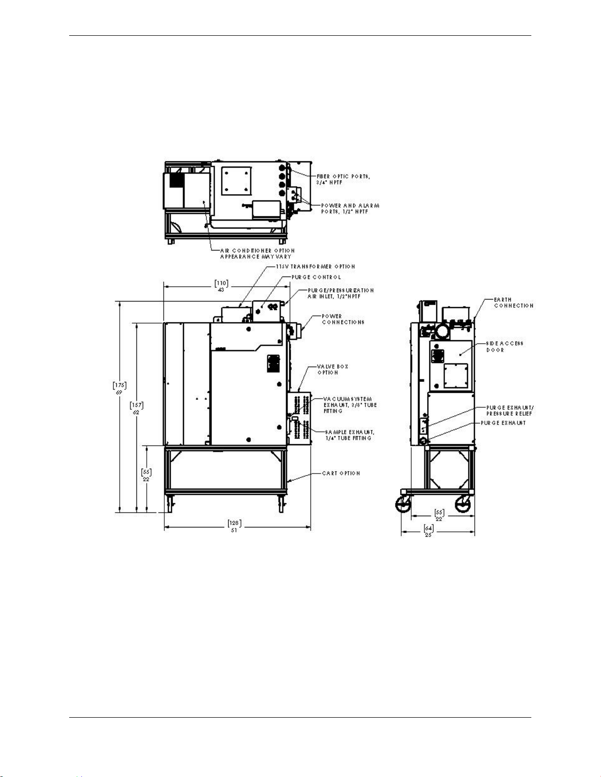
Figure 1: Layout of the ATEX/IECx Zone 1/Class I Div 1 unit (230V or 115V), with cart option ...........8
Figure 2: Layout of the ATEX/IECEx Zone 2 /Class I Div 2 unit (230V or 115V), with cart option ...................9
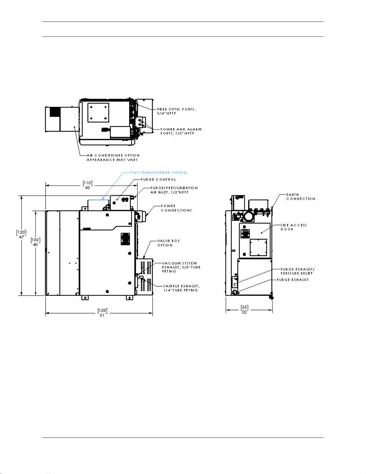
Figure 3: Layout of the ATEX/IECEx Zone 1/Class I Div 1 unit (230V or 115V), without cart option.............10
Figure 4: Layout of the ATEX/IECEx Zone 2/Class I Div 2 unit (230V or 115V), without cart option.............11
................................................................................................................................................................................12
Figure 5: Layout of the ATEX/IECEx Zone 1/Class I Div 1 unit (230V or 115V) with water cooled heat
exchanger and cart option .................................................................................................................................12
................................................................................................................................................................................13
Figure 6: Layout of the ATEX/IECEx Zone 2/Class I Div 2 unit (230V or 115V), with water cooled heat
exchanger and cart option .................................................................................................................................13
Figure 7: Installation Clearances......................................................................................................................14
................................................................................................................................................................................14
SAFETY ...................................................................................................................................................................15
Model Definitions and Marking......................................................................................................................15
WARNINGS ..............................................................................................................................................................18
APPLICATION SUITABILITY......................................................................................................................................24
INSTALLATION.........................................................................................................................................................24
PRESSURIZATION GAS SUPPLY .................................................................................................................................24
SAMPLE GAS SUPPLY.............................................................................................................................................25
AC POWER REQUIREMENTS ....................................................................................................................................26
MAX300-RTG ELECTRICAL CONNECTION DIAGRAMS.........................................................................................27
Figure 8: Power connection diagram, Zone 1/Div 1 units, 230VAC ........................................................27
...........................................................................................................................................................................28
Figure 9: Power connection diagram, Zone 1/Div 1 units, 115VAC ........................................................28
Figure 10: Power connection diagram, Zone 2/Div 2 units, 230VAC ......................................................29
Figure 11: Power connection diagram, Zone 2/Div 2 units, 115VAC ......................................................29
...........................................................................................................................................................................30
Figure 12: Earth connection diagram ...........................................................................................................30
Earthing.............................................................................................................................................................30
Plumbing Connections....................................................................................................................................31
Rotary Valve Inlets..........................................................................................................................................31
Figure 13: Diagram of 16 port rotary valve inlet..........................................................................................33
Figure 14: Diagram of 31 port rotary valve inlet..........................................................................................34
...........................................................................................................................................................................34
Figure 15: Diagram of 46 port rotary valve inlet..........................................................................................35
Figure 16: 16 port rotary valve details..........................................................................................................36
Figure 17: FastValve (40/80/120/160 port valve option) –for use with non-explosive sample ...........37
Calibration Gases............................................................................................................................................37
Figure 18: Calibration Gas Connection........................................................................................................38
Figure 19: External communications disconnect box option.....................................................................41
Status Connections.........................................................................................................................................44
4-20mA Analog Inputs and Outputs .............................................................................................................46
4-20mA Analog Inputs: KL3012 and KL3022..............................................................................................47
4-20mA Output: KL4021 and KL4022 Modules..........................................................................................47
Digital I/O..........................................................................................................................................................48

MAX300-RTG Installation Manual
4
KL1408 –(8) digital input, 24VDC ................................................................................................................49
Relay Output....................................................................................................................................................49
KL2612 (2) Relays...........................................................................................................................................49
Distributed Control System (DCS)................................................................................................................50
INSTRUMENT START-UP..........................................................................................................................................51
General Start-up Procedure...........................................................................................................................51
MAX300-RTG HARDWARE MAINTENANCE ...........................................................................................................53
VENTING THE VACUUM SYSTEM.............................................................................................................................53
Figure 29: Pump Configuration on VacTrac.....................................................................................................55
Pump Maintenance.........................................................................................................................................56
Turbomolecular Vacuum Pump.....................................................................................................................56
Mechanical Vacuum Pump............................................................................................................................57
Inlet Valves.......................................................................................................................................................58
CHANGING THE INLET.............................................................................................................................................59
CHANGING THE IONIZER ASSEMBLY.......................................................................................................................64
QUADRUPOLE MASS FILTER....................................................................................................................................67
Quadrupole Collar Shield Disassembly .......................................................................................................69
QUADRUPOLE CLEANING........................................................................................................................................70
QUADRUPOLE REASSEMBLY AND VACUUM CHAMBER INSTALLATION...................................................................72
ELECTRON MULTIPLIER REMOVAL AND REPLACEMENT ........................................................................................74
REMAINING COMPONENTS IN THE ENCLOSURE........................................................................................................77
RESONATING THE QUADRUPOLE POWER SUPPLY (QC).......................................................................................77
DATA SYSTEM.........................................................................................................................................................79
AIR CONDITIONER...................................................................................................................................................79
VALVE BOX HEATER (OPTIONAL)...........................................................................................................................81
Figure 52: Valve Box Heater, T4, standard option............................................................................................82
Figure 53: Valve Box Heater, high temperature T4 and T3 options..................................................................83
CORROSIVE PUMP OPTION.......................................................................................................................................83
MAX300-RTG Preinstallation Checklist 85

MAX300-RTG: Installation Manual Hardware Installation
5
Introduction
The MAX300™-RTG process mass spectrometer is a versatile real-time process
analyzer capable of fully automatic operation. It can handle a wide range of
applications for quantitative analysis of gases and vapors, as well as monitor
multiple components in any one stream and analyze up to 128 streams (including
calibration gases).
This document is intended to inform the customer of the necessary preparations
for successful installation. As Extrel CMS does not generally inspect a site prior to
installation, it is extremely important to provide the necessary support for the
instrument to avoid significant delays. All utilities and environmental requirements
discussed in this document are the responsibility of the customer. Please note,
depending on which options were purchased, specific accommodations will be
required; refer to the purchase order for clarification.
Installation Requirements
In order for Extrel CMS to assist with the successful installation and operation of
the MAX300-RTG, the customer must:
Complete the Pre-installation Checklist found in Appendix A.
Fax or email to Extrel CMS any legal documents required for access to the
site.
Allocate time for any training programs required for site access.
Prepare a suitable site for the instrument.
Provide and install the required utilities.
Install vent and sample lines and the vacuum system exhaust.
Obtain and install required calibration gases.
Install the compressed air plumbing for the purge systems
Install wiring or fiber for instrument control.
Install wiring for external communications options.
Shelter Requirements
The MAX300-RTG may be located outdoors provided no direct exposure to any
weather conditions exist. A shelter with a 9 ft. (2.75 m) roof, with 7 ft. (2.1 m)
vertical clearance, and at least three sides is required. Although, a fully enclosed
and appropriately designed analyzer shelter is recommended. All environmental

MAX300-RTG: Installation Manual Hardware Installation
6
requirements must be maintained for proper operation of the analyzer. Electrical
power and signal wiring to the instrument must be consistent with instrument
conditions and meet all applicable local building codes. When considering an air
conditioner for the instrumentation housing it is important to keep in mind the heat
dissipation and ambient temperature ranges of the instrument (See Table 1). Any
air conditioner and filter installed in the shelter must be kept clean, unblocked and
allow for adequate air circulation.
Table 1: Temperature considerations for instrument housing.
Area Classification Options
The MAX300-RTG analyzer can be configured for use in these hazardous
locations:
IECEx/ATEX Category 2 (Zone 1), Gas group IIC or IIB+H2, Temperature
code T4 or T3
IECEx/ATEX Category 3 (Zone 2), Gas group IIC, Temperature code T4 or
T3
Class I Division 1, Group BCD, Temperature code T4 or T3
Class I Division 2, Group ABCD, Temperature code T4 or T3
It is imperative to ensure that the appropriate analyzer option is chosen for
installation in the hazardous location.
Please refer to the Safety section of this manual for more information.
Specifications
Power requirements:
115V 60 hz option: 115(+/- 10%) VAC, 60 Hz, single phase, two 20 amp
circuits required
Type
Range
Heat Dissipation
10,200 Btu/hour, A/C:6000 Btu/hour
3 Kilowatts, A/C: 1.8 Kilowatts
Ambient Temperature Range
-4oF (-20oC) to 122oF (50oC )
A/C cold start ≥ 54oF (12oC)

MAX300-RTG: Installation Manual Hardware Installation
7
115V 50/60 hz option: 115(+/- 10%) VAC, 50/60 Hz, single phase, two 20
amp circuits required
230V option: 230(+/- 10%) VAC, 50/60 Hz, single phase, one 20 amp circuit
required
Ambient temperature: -20°C to 50°C
Purge/pressurization gas requirements:
Purge/pressurization gas - Clean, dry instrument quality air or inert gas
Zone 1/Div 1 units: 620 –793 kPa (90 –115 psig), 300 LPM (10.6 SCFM)
purge, 80 LPM (2.8 SCFM) continuous
Zone 2/Div 2 units: 414 –793 kPa (60 –115 psig), 142 LPM (5 SCFM)
continuous
T rating: T4 (135°C) or optional T3 (200°C)
Maximum surface temperature: 130°C for T4 units, 190°C for T3 units
Tool required for opening enclosure doors: Screwdriver, flat blade, 9 mm (3/8”)
wide
Weight: 182 kg (400 lbs) approximately (option dependent)

MAX300-RTG: Installation Manual Hardware Installation
8
Figure 1: Layout of the ATEX/IECx Zone 1/Class I Div 1 unit (230V or 115V), with
cart option

MAX300-RTG: Installation Manual Hardware Installation
9
Figure 2: Layout of the ATEX/IECEx Zone 2 /Class I Div 2 unit (230V or 115V), with
cart option

MAX300-RTG: Installation Manual Hardware Installation
10
Figure 3: Layout of the ATEX/IECEx Zone 1/Class I Div 1 unit (230V or 115V), without
cart option

MAX300-RTG: Installation Manual Hardware Installation
11
Figure 4: Layout of the ATEX/IECEx Zone 2/Class I Div 2 unit (230V or 115V), without
cart option

MAX300-RTG: Installation Manual Hardware Installation
12
Figure 5: Layout of the ATEX/IECEx Zone 1/Class I Div 1 unit (230V or 115V) with
water cooled heat exchanger and cart option

MAX300-RTG: Installation Manual Hardware Installation
13
Figure 6: Layout of the ATEX/IECEx Zone 2/Class I Div 2 unit (230V or 115V), with
water cooled heat exchanger and cart option

MAX300-RTG: Installation Manual Hardware Installation
14
Figure 7: Installation Clearances

MAX300-RTG: Installation Manual Hardware Installation
15
Safety
Model Definitions and Marking
MAX300-RTG is available in several models that are suitable for installation in
various hazardous areas. It is the responsibility of the user to ensure that the
appropriate model has been chosen for a particular hazardous location. Below is
a listing of the models and the parameters that apply.
ATEX/IECEX Category 2 (Zone 1) models:
MAX300-RTG-Z1CF –II 2 G Ex db ib mb pxb IIC T4 Gb
MAX300-RTG-Z1C - II 2 G Ex db ib pxb IIC T4 Gb
MAX300-RTG-Z1BF - II 2 G Ex db ib mb pxb IIB+H2 T4 Gb
MAX300-RTG-Z1B - II 2 G Ex db ib pxb IIB+H2 T4 Gb
MAX300-RTG-Z1CFT3 –II 2 G Ex db ib mb pxb IIC T3 Gb
MAX300-RTG-Z1CT3 - II 2 G Ex db ib pxb IIC T3 Gb
MAX300-RTG-Z1BFT3 - II 2 G Ex db ib mb pxb IIB+H2 T3 Gb
MAX300-RTG-Z1BT3 - II 2 G Ex db ib pxb IIB+H2 T3 Gb
Certificate number: IECEx ETL 17.0031X, ITS17ATEX11959X
Tamb
-20°C to 50°C
Internal free volume
436 L
Purging gas
Air or inert
Minimum overpressure
0.50 mbar
Normal overpressure
2.5 mbar
Maximum overpressure
5 mbar
Maximum leakage rate
50 L/m
Minimum purge flow rate
300 NL/m
Minimum purge time
12 m
Minimum continuous dilution flow
rate
80 NL/m
Supply pressure
4 to 8 bar
Enclosure with a containment
system
Limited internal source of
release
Maximum sample flow rate
0.034 L/m
Maximum sample supply pressure
20 PSIG

MAX300-RTG: Installation Manual Hardware Installation
16
ATEX/IECEX Category 3 (Zone 2) models :
MAX300-RTG-Z2CF –II 3 G Ex ib mb pzc IIC T4 Gc
MAX300-RTG-Z2CFIQ –II 3 G Ex ib mb nA nC pzc IIC T4 Gc
MAX300-RTG-Z2C –II 3 G Ex ib pzc IIC T4 Gc
MAX300-RTG-Z2CIQ –II 3 G Ex ib nA nC pzc IIC T4 Gc
MAX300-RTG-Z2CFH –II 3 G Ex db ib mb pzc IIC T4 Gc
MAX300-RTG-Z2CFHIQ –II 3 G Ex db ib mb nA nC pzc IIC T4 Gc
MAX300-RTG-Z2CH –II 3 G Ex db ib pzc IIC T4 Gc
MAX300-RTG-Z2CHIQ –II 3 G Ex db ib nA nC pzc IIC T4 Gc
MAX300-RTG-Z2CFHT3 –II 3 G Ex db ib mb pzc IIC T3 Gc
MAX300-RTG-Z2CFHIQT3 –II 3 G Ex db ib mb nA nC pzc IIC T3 Gc
MAX300-RTG-Z2CHT3 –II 3 G Ex db ib pzc IIC T3 Gc
MAX300-RTG-Z2CHIQT3 –II 3 G Ex db ib nA nC pzc IIC T3 Gc
Certificate number: IECEx ETL 17.0031X, ITS17ATEX11959X
Tamb
-20°C to 50°C
Internal free volume
436 L
Purging gas
Air or inert
Minimum overpressure
0.25 mbar
Normal overpressure
2.5 mbar
Maximum overpressure
5 mbar
Maximum leakage rate
50 L/m
Minimum purge flow rate
142 NL/m
Minimum purge time
12 m
Minimum continuous dilution flow
rate
142 NL/m
Supply pressure
4 to 8 bar
Enclosure with a containment
system
No release
Maximum sample flow rate
0.034 L/m
Maximum sample supply pressure
20 PSIG

MAX300-RTG: Installation Manual Hardware Installation
17
North American Class I Division 1 models:
MAX300-RTG-D1B -
Class I Division 1 groups BCD
ETL Listing Control Number: 5009393
Pressurization type X
Temperature Class T4
MAX300-RTG-D1BT3 -
Class I Division 1 groups BCD
ETL Listing Control Number: 5009393
Pressurization type X
Temperature Class T3
North American Class I Division 2 models:
MAX300-RTG-D2A -
Class I Division 2 groups ABCD
ETL Listing Control Number: 5009393
Pressurization type Z
Temperature Class T4
MAX300-RTG-D2AT3-
Class I Division 2 groups ABCD
ETL Listing Control Number: 5009393
Pressurization type Z

MAX300-RTG: Installation Manual Hardware Installation
18
Temperature Class T3
Warnings
WARNING –Pressurized enclosure –When ignitable combustible materials
are present, the MAX300 enclosure must not be opened until a cooldown period
of 5 minutes is observed. Power must not be restored after enclosure has been
opened until unit has been properly purged. ATEX/IECEx Category 2 (Zone 1)
and Class I Div 1 models are equipped with a purge/pressurization device that
automatically connects power after an appropriate purge interval, and
disconnects power upon loss of pressurization. ATEX/IECEx Category 3 (Zone
2) and Class I Div 2 models are equipped with a manual pressurization device
that requires a 12 minute minimum purge prior to connecting power. This device
is equipped with pressurization loss switch contacts and indicators.
AVERTISSEMENT –Enceinte sous pression –En présence de matières
combustibles inflammables, l’enceinte MAX300 ne doit pas être utilisée avant
qu’une période de refroidissement de 5 minutes se soit écoulée. Après
l’ouverture de l’enceinte, l’alimentation électrique ne doit pas être rétablie avant
la vidange appropriée de l’appareil. Les modèles ATEX/IECEx de catégorie 2
(zone 1) et de classe I, division 1 sont munis d’un dispositif de
vidange/pressurisation qui remet automatiquement l’alimentation électrique après
un délai de vidange appropriée, et coupe l’alimentation après une
dépressurisation. Les modèles ATEX/IECEx de catégorie 3 (zone 2) et de
classe I, division 2 sont munis d’un dispositif de pressurisation manuel qui
requiert une vidange au moins 12 minutes avant le branchement de
l’alimentation électrique. Cet appareil est pourvu d’interrupteurs de contact et
d’indicateurs de dépressurisation.
WARNING - Substitution of components of the MAX300 unit may impair
suitability for hazardous locations. Contact Extrel CMS technical support prior to
component substitution.
AVERTISSEMENT - La substitution de composants de l’unité MAX300 peut
compromettre sa capacité à bien fonctionner dans des endroits dangereux.
Communiquez avec le soutien technique Extrel CMS avant d’effectuer la
substitution de tout composant.

MAX300-RTG: Installation Manual Hardware Installation
19
WARNING - It is the user’s responsibility to ensure that this unit is installed and
used in a safe manner, in accordance with applicable national and local safety
standards.
AVERTISSEMENT - Il incombe à l’utilisateur de s’assurer que cet appareil est
installé et utilisé de façon sécuritaire, conformément aux normes de sécurité
nationales et locales applicables.
WARNING –Potential electrostatic charging hazard
When cleaning the exterior painted surface of the unit in a hazardous area, use a
damp cloth to avoid potential electrostatic charging.
AVERTISSEMENT –Danger potentiel de charge électrostatique
Au moment de nettoyer la surface extérieure peinte de l’appareil dans une zone
dangereuse, utiliser un chiffon humide pour éviter tout risque de charge
électrostatique.
WARNING –Piping of the protective gas (air) to the enclosure shall be protected
against mechanical damage.
AVERTISSEMENT –La tuyauterie du gaz protecteur (air) vers l’enceinte doit être
protégée des dommages mécaniques.
WARNING –For power connections to the unit, use wire suitable for use at a
temperature of 80°C or higher.
AVERTISSEMENT –Pour les connexions électriques vers l’appareil, utiliser un fil
convenant à des températures égales ou supérieures à 80 °C.
WARNING –This unit contains a lithium backup battery, used to supply power to
the computer real-time clock. The battery circuit is intrinsically safe and requires
no maintenance. The battery is not user serviceable –contact Extrel CMS
technical support for more information.
AVERTISSEMENT –Cet appareil comporte une pile de secours au lithium, qui
sert à alimenter l’horloge en temps réel de l’ordinateur. Le circuit de la pile est
intrinsèquement sûr et ne nécessite aucun entretien. La pile ne peut être réparée

MAX300-RTG: Installation Manual Hardware Installation
20
par l’utilisateur; communiquez avec le soutien technique Extrel CMS pour plus de
renseignements.
WARNING –The gas inlet to the mass spectrometer includes a “containment
system” that allows sample gas to be safely introduced. Replacement of any inlet
parts must be done using new Extrel approved components while carefully
following the instructions in this manual. Contact Extrel CMS technical support for
more information.
AVERTISSEMENT –L’entrée de gaz au spectromètre de masse comprend un
« système de confinement » qui permet à l’échantillon de gaz d’être ajouté en toute
sécurité. En cas de remplacement de toute pièce d’entrée, il faut utiliser des
composants neufs approuvés Extrel et respecter à la lettre les instructions du
présent manuel. Communiquez avec le soutien technique Extrel CMS pour plus
de renseignements.
WARNING –If unit is equipped with external communications disconnect box (see
page 38), nothing is to be installed within 50 mm of flameproof enclosure joint.
AVERTISSEMENT –Si l’appareil est muni d’un boîtier sectionneur pour
communications externes (voir page 38), rien ne doit être installé à moins de
50 mm du joint de l’enceinte ignifuge.
WARNING –If unit is purged with inert gas instead of compressed air, it may be
an asphyxiation hazard.
AVERTISSEMENT –Lors de l’utilisation de gaz inerte comme gas de protection,
il pourrait y avoir un risque d’asphyxie.
ATEX/IECEx Category 2 (Zone 1) and Class I Div 1
This unit is intended for use in ATEX/IEC Category 2 (Zone 1) or Class I Division
1 locations. It is designed for group IIC or groups ABCD hazards (IIB+H2 or BCD
with communications box option), where the hazardous area is non-mining (above
ground) and the hazard is caused by flammable gases or vapors.
The instrument is made suitable for hazardous locations via a purge and
pressurization technique, known as “px” or “x” purge. This design allows purge
gas, also known as the protective gas, to be admitted into the enclosure from a
Table of contents
Popular Industrial Equipment manuals by other brands

ACS
ACS FRV Seroes Operation and instruction manual

ABB
ABB HT604625 Operation manual

Hitachi
Hitachi KPI-252-2002E4E Installation and operation manual

Spirax Sarco
Spirax Sarco UTD30 Series Installation and maintenance instructions

ITOH DENKI
ITOH DENKI F-RAT-NX75 operating instructions

Moxa Technologies
Moxa Technologies V2616 Series user manual