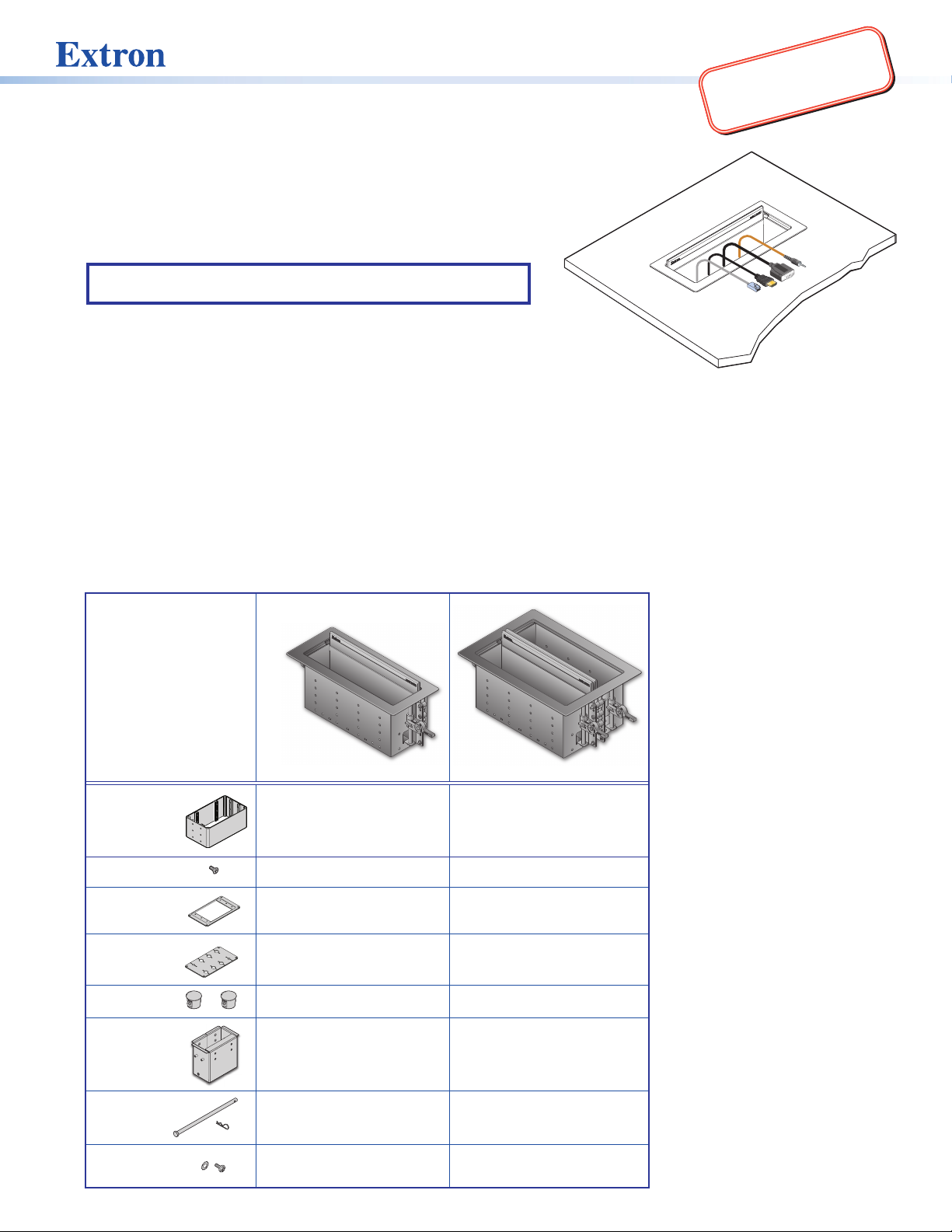
Extron electronics Cable Cubby 1202 User manual
Other Extron electronics Cable Box manuals

Extron electronics
Extron electronics Cable Cubby 200 User manual

Extron electronics
Extron electronics TP R AV User manual

Extron electronics
Extron electronics HDMI 101 Plus User manual

Extron electronics
Extron electronics Dual Length DVI Cable Equalizer DVI DL 101 User manual

Extron electronics
Extron electronics Cable Cubby 500 User manual

Extron electronics
Extron electronics Cable Cubby 1202 User manual

Extron electronics
Extron electronics Retractor SM User manual
Popular Cable Box manuals by other brands


Commercial Electric
Commercial Electric 5053-WH installation guide

Motorola
Motorola DCT6412 DUAL-TUNER DVR AND HD SET-TOP - MICROSOFT... User's reference manual

Renkforce
Renkforce 1395556 operating instructions

Huawei
Huawei FAT9102SD-32G Quick installation guide

VISSEM Electronics
VISSEM Electronics Opticube VSOF-OTB-E manual

Beta
Beta 1844 15-H05/SCK Instructions for use

FSR
FSR FL-1550 installation instructions

Renkforce
Renkforce 1674559 operating instructions

Minebea Intec
Minebea Intec PR 6130/64Sa installation manual

KS Tools
KS Tools efuturo Wallbox operating instructions

Chatsworth Products
Chatsworth Products Evolution installation instructions

Minebea Intec
Minebea Intec Weighbridge PR 6021/68S installation manual