Extron electronics VTG 300 User manual
VTG 300/300R • Setup Guide
NOTE: Prior to using the VTG 300R for the first time, please be sure that the batteries are
fully charged.
To operate the VTG 300/300R, follow these steps (see the Operations section of the user
guide for detailed instructions).
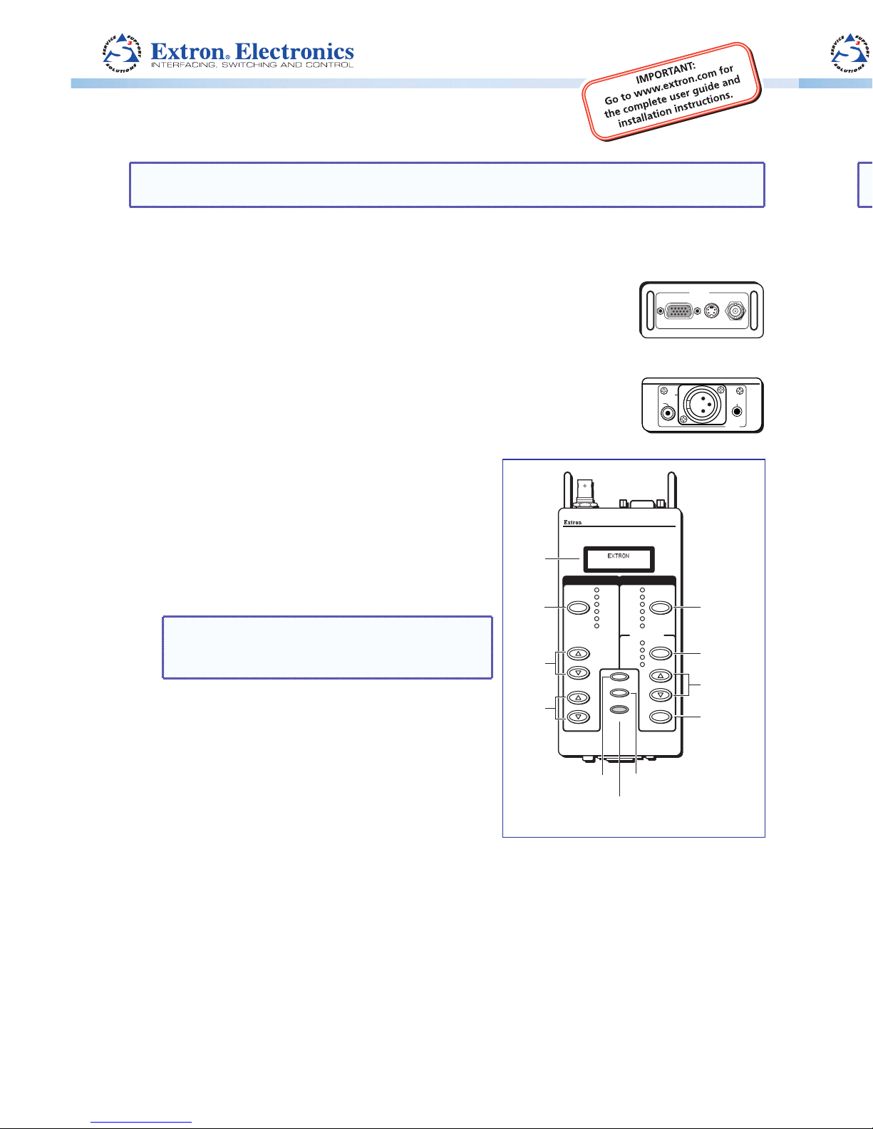
1. Connect a video device to one of the top panel connectors or
RGB/R-Y,Y,B-Y S-VIDEO COMPOSITE
VIDEO
Top panel
connect an audio device to one of the bottom panel connectors.
The video connectors located on the top panel will accommodate
RGB, component, S-video, and composite video output.
The audio connectors located on the bottom panel will
AUDIO
3
2
1
Bottom panel
accommodate unbalanced mono audio on the RCA jack, balanced
mono audio on the 3-pin XLR connector, and unbalanced mono
audio (both left and right channels) on the 3.5 mm mini jack.
2. Power up the VTG 300/300R.
VTG 300R
VIDEO & AUDIO TEST GENERATOR
SIGNAL
TEST
PATTERNS
RANGE
OUTPUT RATE
RATE
MENU
NEXT
POWER
SELECT
LEVEL
FREQUENCY
P.NOISE
W. NOISE
SINE
SQUARE
POLARITY
SWEEP
X-HATCH
H PATTERN
COL. BARS
GRAYSCALE
ALT/ MULTI
WHT. FIELD
PC
VIDEO
HDTV
16:9 HR
AUDIO VIDEO
Signal
Button
Level
Buttons
Frequency
Buttons
Menu
Button
Next
Button
Power
Button
Test Patterns
Button
Range
Button
Rate
Button
Select
Button
LCD
Display VTG 300R
Front panel
Using either the external power supply or
Internal batteries, hold down the Power button
for one second.
3. If generating an audio signal, press the audio
Signal button to select an audio signal, as
indicated by the lit LED. Press the audio Level
buttons to adjust the RMS signal level.
NOTE: See the Audio Setup Menu section
of the User Guide to specify either dBu or
dBV as the signal level unit.
When the signal type is either a sine or square
wave, press the Frequency buttons to adjust
the frequency from 20 Hz to 20 kHz (sine) or
20 Hz to 5 kHz (square).
When the signal type is frequency sweep, press
the Frequency buttons to adjust the sweep
interval from 1.5 sec to 150 sec.
4. If generating a video signal, press the Test
Patterns button to select a test pattern type, as indicated by the lit LED (see
Selecting a Video Test Pattern of the User Guide).
Press the Range button to select from among the four video range types, as indicated
by the lit LED.
Press the Rate buttons to select from among the scan rates for the selected range, then
press the Select button to activate the selection.
VTG 300/300R • Setup Guide
NOTE: Prior to using the VTG 300R for the first time, please be sure that the batteries are
fully charged.
To operate the VTG 300/300R, follow these steps (see the Operations section of the User
Guide for detailed instructions).
1. Connect a video device to one of the top panel connectors or
RGB/R-Y,Y,B-Y S-VIDEO COMPOSITE
VIDEO
Top panel
connect an audio device to one of the bottom panel connectors.
The video connectors located on the top panel will accommodate
RGB, component, S-video, and composite video output.
The audio connectors located on the bottom panel will
AUDIO
3
2
1
Bottom panel
accommodate unbalanced mono audio on the RCA jack, balanced
mono audio on the 3-pin XLR connector, and unbalanced mono
audio (both left and right channels) on the 3.5 mm mini jack.
2. Power up the VTG 300/300R.
VTG 300R
VIDEO & AUDIO TEST GENERATOR
SIGNAL
TEST
PATTERNS
RANGE
OUTPUT RATE
RATE
MENU
NEXT
POWER
SELECT
LEVEL
FREQUENCY
P.NOISE
W. NOISE
SINE
SQUARE
POLARITY
SWEEP
X-HATCH
H PATTERN
COL. BARS
GRAYSCALE
ALT/ MULTI
WHT. FIELD
PC
VIDEO
HDTV
16:9 HR
AUDIO VIDEO
Signal
Button
Level
Buttons
Frequency
Buttons
Menu
Button
Next
Button
Power
Button
Test Patterns
Button
Range
Button
Rate
Button
Select
Button
LCD
Display VTG 300R
Front panel
Using either the external power supply or
Internal batteries, hold down the Power button
for one second.
3. If generating an audio signal, press the audio
Signal button to select an audio signal, as
indicated by the lit LED. Press the audio Level
buttons to adjust the RMS signal level.
NOTE: See the Audio Setup Menu section
of the User Guide to specify either dBu or
dBV as the signal level unit
When the signal type is either a sine or square
wave, press the Frequency buttons to adjust
the frequency from 20 Hz to 20 kHz (sine) or
20 Hz to 5 kHz (square).
When the signal type is frequency sweep, press
the Frequency buttons to adjust the sweep
interval from 1.5 sec to 150 sec.
4. If generating a video signal, press the Test
Patterns button to select a test pattern type, as indicated by the lit LED (see
Selecting a Video Test Pattern of the User Guide).
Press the Range button to select from among the four video range types, as indicated
by the lit LED.
Press the Rate buttons to select from among the scan rates for the selected range, then
press the Select button to activate the selection.

VTG 300/300R • Setup Guide (Continued)
Extron USA - West
Headquarters
+800.633.9876
Inside USA and
Canada Only
+1.714.491.1500
+1.714.491.1517 FAX
Extron USA - East
+800.633.9876
Inside USA and
Canada Only
+1.919.863.1794
+1.919.863.1797 FAX
Extron Europe
+800.3987.6673
Inside Europe Only
+31.33.453.4040
+31.33.453.4050 FAX
Extron Asia
+800.7339.8766
Inside Asia Only
+65.6383.4400
+65.6383.4664 FAX
Extron Japan
+81.3.3511.7655
+81.3.3511.7656 FAX
Extron China
+400.883.1568
Inside China Only
+86.21.3760.1568
+86.21.3760.1566 FAX
Extron Middle East
+971.4.2991800
+971.4.2991880 FAX
© 2011 Extron Electronics All rights reserved. www.extron.com
68-737-50
Rev. A 10 11
68-737-50
Rev. A 10 11
Menu System
Use the Menu button to advance through the main menus. Use the Next button to navigate
through the submenu system (see the Menus, Configuration, and Adjustments section
of the User Guide).
zTest Pattern Setup
zGrayscale — To change the grayscale test pattern, select the Grayscale submenu
from the Test Patterns main menu. Use the and buttons to select 32-Level
or Ramp.
zWhite Field — To change to the white field test pattern select the White Field
submenu from the Test Patterns main menu. Use the and buttons to select
Full Field,Window 80%, or Window 20%.
zAudio Setup
zUnits — To select the audio level units select the Units submenu from the Audio
Setup main menu. Use the and buttons to select dBV or dBu.
zOutput 3 — To change the audio output format from Output #3 (3.5mm) select the
Output 3 submenu from the Audio Setup main menu. Use the and buttons
to select Left Only, Right Only, or Left + Right.
zVideo Setup
zHD15 Format — To select the format of the video for the HD15 output select HD15
Format submenu from the Video Setup Main menu. Use the and buttons to
select RGB or Y, B-Y,R-Y as the output format.
zRGB Sync Format — To select a sync format for the HD15 output, select the RGB
Sync Fmt submenu from the Video Setup Main menu. Use the and buttons
to select RGBHV, RsGsBs, RGsB or RGBS as the output sync format.
zAdvanced Setup
zPower Off Timer — To change the time setting for the automatic power off
feature select the PwrOff Timer submenu from the Advanced setup main menu.
Use the and buttons to select Disabled, 30 min, 15 min, or 5 min as the
setting.
zButton Lock Mode
zTo prevent unwanted configuration changes Button Lock mode can be enabled.
Simultaneously press and hold the Signal button and Test Patterns button for
two seconds. When the Button Lock mode has been enabled the message “Button
Lock Enabled” is displayed for two seconds.
zTo disable Button Lock mode simultaneously press and hold the Signal button and
Test Patterns button for two seconds. When the Button Lock mode has been
disabled the message “Button Lock Disabled” is displayed for two seconds.
This manual suits for next models
1
Table of contents
Other Extron electronics Inverter manuals


Popular Inverter manuals by other brands


BARRON
BARRON EXITRONIX Tucson Micro Series installation instructions

Baumer
Baumer HUBNER TDP 0,2 Series Mounting and operating instructions

electroil
electroil ITTPD11W-RS-BC Operation and Maintenance Handbook

Silicon Solar
Silicon Solar TPS555-1230 instruction manual

Mission Critical
Mission Critical Xantrex Freedom SW-RVC owner's guide

HP
HP 3312A Operating and service manual


