MTP 1500RL 15HD A SEQ • Setup Guide (Continued)
Extron Headquarters
+800.633.9876 Inside USA/Canada Only
Extron USA - West Extron USA - East
+1.714.491.1500 +1.919.863.1794
+1.714.491.1517 FAX +1.919.863.1797 FAX
Extron Europe
+800.3987.6673
Inside Europe Only
+31.33.453.4040
+31.33.453.4050 FAX
Extron Asia
+800.7339.8766
Inside Asia Only
+65.6383.4400
+65.6383.4664 FAX
Extron Japan
+81.3.3511.7655
+81.3.3511.7656 FAX
Extron China
+4000.EXTRON
+4000.398766
Inside China Only
+86.21.3760.1568
+86.21.3760.1566 FAX
Extron
Middle East
+971.4.2991800
+971.4.2991880 FAX
Extron Korea
+82.2.3444.1571
+82.2.3444.1575 FAX
Extron India
1800.3070.3777
Inside India Only
+91-80-3055.3777
+91 80 3055 3737 FAX
©2012 Extron Electronics All rights reserved. www.extron.com
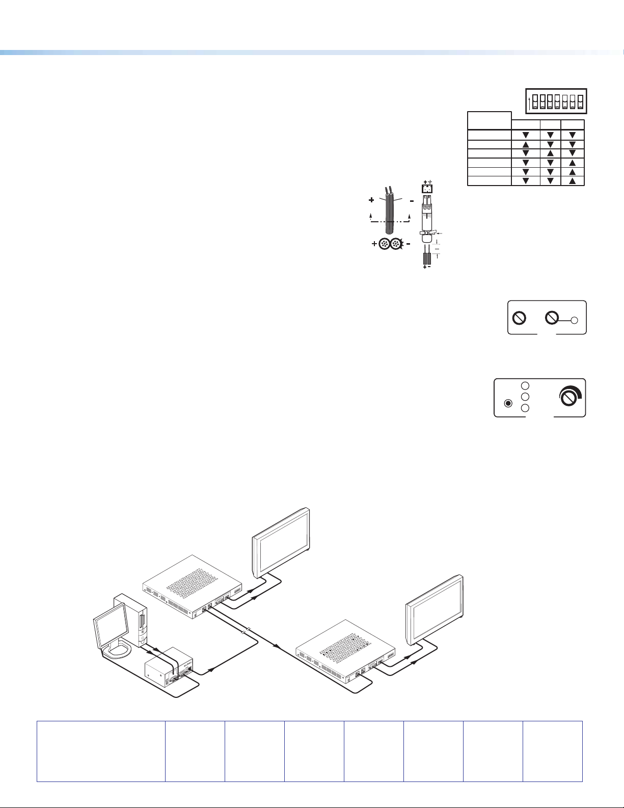
Step 4 — Receiver DIP switches
zH sync (H+) and V sync (V+) switches — Set these switches up (On) for positive sync
or down (Off) for negative sync.
zComposite Sync, SOG, and Video switches — Set these switches as shown
in the table (see right) to output the indicated format.
zEnd Unit switch — Set this switch up if either of the following is true:
a. The receiver being configured is the only receiver connected to the transmitter.
b. The receiver being configured is the last receiver in a daisy-chained system.
Step 5 — Power
a. Plug the included 12 VDC power supply into the 2-pole
captive screw connector.
b. Wire the connector as shown at right.
Step 6 — Peaking and Level
Adjust image sharpness with the Peaking control. Increased peaking compensates for mid- and high-frequency detail loss.
The LED lights red when minimum (zero) and maximum peaking is reached.
Adjust image brightness using the Level control. View the image and adjust either control for the best
image quality.
Step 7 — Skew compensation
Pair skew can be measured with test equipment or by viewing a crosshatch test pattern. The SEQ receivers have built-in
skew compensation capabilities. Adjust the equalization as follows:
a. Set the skew delay to zero for red, green, and blue by pressing and holding the Select
button in for 3 seconds, using a Tweeker or small screwdriver. When the Red, Green, and
Blue LEDs all go out, release the Select button.
b. Use UTP cable test equipment or examine the displayed image to determine which video
signal — red, green, or blue — is shifted furthest to the left.
c. Adjust the furthest left video signal by using a Tweeker or screwdriver to press and release the Select button
until the LED for the left-shifted color lights.
d. Slowly rotate the Adjust control clockwise until the shifted color is properly aligned.
e. Repeat steps 7c and 7d to align the third color if needed.
68-1554-50 Rev. B
01 12
DELAY
RED
GREEN
BLUE
SELECT
ADJUST
RGB
PEAKING
LEVEL
MIN/MAX
Power Supply
Output Cord
SECTION A–A
Ridges
Smooth
Captive
Screw
Connector
Tie Wrap
3"
16 (5 mm) Max.
MTP1500RL 15HD A SEQ
POWER
12V
0.5AMAX
OUTPUT
MONO
LR
AUDIO
H+
V+
CSYNC
SOG
VIDEO
END
SPARE
ON
INPUT BUFFEREDOUTPUT
MTP
MTP
MTP1500RL 15HD A SEQ
POWER
12V
0.5AMAX
OUTPUT
MONO
L R
AUDIO
H+
V+
CSYNC
SOG
VIDEO
END
SPARE
ON
INPUT BUFFEREDOUTPUT
MTP
MTP
PC
Flat Panel
Display
Flat Panel
Display
1,000' (305 m) UTP Cable
(CAT 5/5e/6)
Audio
AudioAudio
RGBHV
RGBHV500' (152 m) UTP Cable
(CAT 5/5e/6)
RGBHV
Extron
MTP 1500RL 15HD A SEQ
Extron
MTP T 15HD A
Extron
MTP 1500RL 15HD A SEQ
Figure 1. Example of a typical MTP 1500RL 15HD A SEQ application
ON
H +
V +
SOG
VIDEO
END
SPARE
Format
Output
Format C Sync SOG Video
RGBHV
RGBS
RGsB
Component*
S-video*
Composite*
* Input video format must match.


