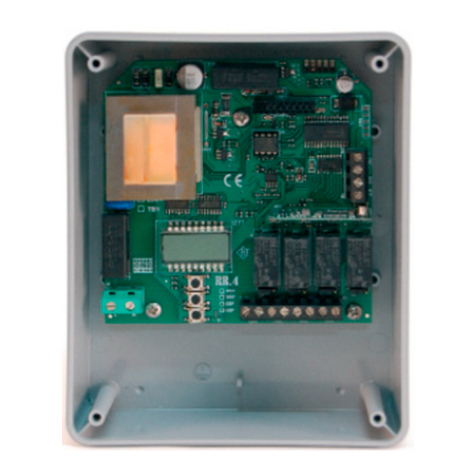
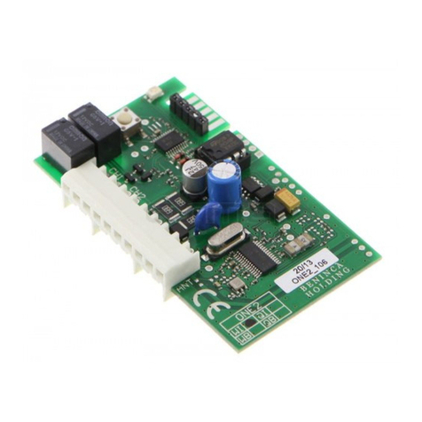
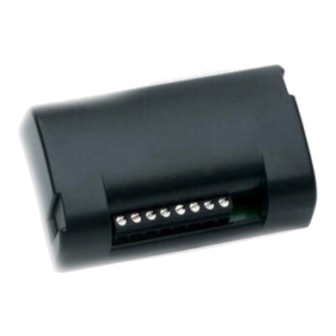
Beninca ONE.4WB User manual

L8543099
10/2016 rev 1
ONE.4WB
UNIONE NAZIONALE COSTRUTTORI
AUTOMATISMI PER CANCELLI, PORTE
SERRANDE ED AFFINI

2
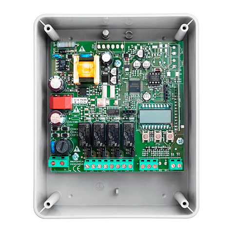
U6
RADIO
ADV
CH1 CH2 CH3 CH4
N
F1
T1A
L
SHIELD
ANT
ANT
IN2
IN1
COM
J4
J3
J2
J1
CH1 N.O.
CH1 N.C.
CH20 N.O.
CH2 N.C.
CH3 N.O.
CH3 N.C.
CH4 N.O.
CH4 N.C.

3
ITA AVVERTENZE
INFORMAZIONI GENERALI
E’ vietato l’utilizzo del prodotto per scopi o con modalità non previste nel presente manuale. Usi non corretti
possono essere causa di danni al prodotto e mettere in pericolo persone e cose. Si declina ogni responsabilità
dall’inosservanza della buona tecnica nella costruzione dei cancelli, nonché dalle deformazioni che potrebbero
verificarsi durante l’uso. Conservare questo manuale per futuri utilizzi.
INFORMAZIONI PER L'INSTALLATORE
Questo manuale è destinato esclusivamente a personale qualificato per l’installazione e la manutenzione di
aperture automatiche.
L’installazione deve essere effettuaua da personale qualificato (installatore professionale, secondo EN12635),
nell’osservanza della Buona Tecnica e delle norme vigenti. Verificare che la struttura del cancello sia adatta
ad essere automatizzata.
L’installatore deve fornire tutte le informazioni relative al funzionamento automatico, manuale e di emergenza
dell’automazione, e consegnare all’utilizzatore dell’impianto le istruzioni d’uso.
AVVERTENZE GENERALI
I materiali dell’imballaggio non devono essere lasciati alla portata dei bambini in quanto fonte di potenziale
pericolo. Non disperdere nell’ambiente i materiali di imballo, ma separare le varie tipologie (es. cartone,
polistirolo) e smaltirle secondo le normative locali.
Non permettere ai bambini di giocare con i dispositivi di comando del prodotto. Tenere i telecomandi lontano
dai bambini.
Questo prodotto non è destinato a essere utilizzato da persone (bambini inclusi) con capacità fisiche, sen-
soriali o mentali ridotte, o con mancanza di conoscenze adeguate, a meno che non siano sotto supervisione
o abbiano ricevuto istruzioni d’uso da persone responsabili della loro sicurezza. Applicare tutti i dispositivi
di sicurezza (fotocellule, coste sensibili, ecc.) necessari a proteggere l’area da pericoli di impatto, schiaccia-
mento, convogliamento, cesoiamento. Tenere in considerazione le normative e le direttive in vigore, i criteri
della Buona Tecnica, l’utilizzo, l’ambiente di installazione, la logica di funzionamento del sistema e le forze
sviluppate dall’automazione.
L’installazione deve essere fatta utilizzando dispositivi di sicurezza e di comandi conformi alla EN12978 e
EN12453.
Raccomandiamo di utilizzare accessori e parti di ricambio originali, utilizzando ricambi non originali il prodotto
non sarà più coperto da garanzia.
Tutte le parti meccaniche ed elettroniche che compongono l'automazione soddisfano i requisiti e le norme
in vigore e presentano marcatura CE.
SICUREZZA ELETTRICA
Prevedere sulla rete di alimentazione un interruttore/sezionatore onnipolare con distanza d’apertura dei
contatti uguale o superiore a 3 mm.
Verificare che a monte dell’impianto elettrico vi sia un interruttore differenziale e una protezione di sovra-
corrente adeguati.
Alcune tipologie di installazione richiedono il collegamento dell’anta ad un impianto di messa a terra rispon-
dente alle vigenti norme di sicurezza.
Durante gli interventi di installazione, manutenzione e riparazione, togliere l’alimentazione prima di accedere
alle parti elettriche.
Scollegare anche eventuali batterie tampone se presenti. L’installazione elettrica e la logica di funzionamento
devono essere in accordo con le normative vigenti. I conduttori alimentati con tensioni diverse, devono essere
fisicamente separati, oppure devono essere adeguatamente isolati con isolamento supplementare di almeno 1
mm. I conduttori devono essere vincolati da un fissaggio supplementare in prossimità dei morsetti. Ricontrol-
lare tutti i collegamenti fatti prima di dare tensione. Gli ingressi N.C. non utilizzati devono essere ponticellati.
SMALTIMENTO
Come indicato dal simbolo a lato, è vietato gettare questo prodotto nei rifiuti domestici in quanto alcune
parti che lo compongono potrebbero risultare nocive per l’ambiente e la salute umana, se smaltite scorret-
tamente. L’apparecchiatura, pertanto, dovrà essere consegnata in adeguati centri di raccolta differenziata,
oppure riconsegnata al rivenditore al momento dell’acquisto di una nuova apparecchiatura equivalente. Lo
smaltimento abusivo del prodotto da parte dell’utente comporta l’applicazione delle sanzioni amministrative
previste dalla normativa vigente.
Le descrizioni e le illustrazioni presenti in questo manuale non sono impegnative. Lasciando inalterate le caratteristiche
essenziali del prodotto il fabbricante si riserva il diritto di apportare qualsiasi modifica di carattere tecnico, costruttivo o
commerciale senza impegnarsi ad aggiornare la presente pubblicazione.
4
ONE.4WB
1) CARATTERISTICHE TECNICHE
- Quattro canali di uscita indipendenti liberamente configurabili
- Radioricevitore con frequenza 433,92MHz configurabile Rolling Code HCS/Advanced Rolling Code (ARC)/Codice Fisso.
- Programmazione a mezzo display LCD incorporato
- Programmazione a mezzo programmatore ADVANTOUCH e relativo software per PC Windows (opzionale).
1.1) FUNZIONI INGRESSI/USCITE
N° Ingresso Funzione Descrizione
L-N Alimentazione Ingresso alimentazione 90-255Vac 50/60Hz
CH1 Canale 1 Uscita canale 1. Max 250Vac/5A.
Contatto N.O., commutabile in N.C. spostando il jumper J1.
CH2 Canale 2 Uscita canale 2. Max 250Vac/5A.
Contatto N.O., commutabile in N.C. spostando il jumper J2.
CH3 Canale 3 Uscita canale 3. Max 250Vac/5A.
Contatto N.O., commutabile in N.C. spostando il jumper J3.
CH4 Canale 4 Uscita canale 4. Max 250Vac/5A.
Contatto N.O., commutabile in N.C. spostando il jumper J4.
COM-IN1-IN2 Ingresso 1 e 2
Ingressi configurabili mediante il menu parametri e logiche, possono
attivare uno dei canali CH1/CH2/CH3/CH4, in modo analogo ad un
trasmettitore radio.
ANT-SHIELD Antenna Collegamento antenna del modulo radio incorporato
ADV Connettore
ADVANTOUCH
Ingresso per connettore ADVANTOUCH (Cavo C4).
Consente la gestione della memoria della ricevente tramite il software
ADVANTOUCH ed il relativo programmatore.
Fate riferimento alle istruzioni ADVANTOUCH per ulteriori informazioni.
Nota:
La memoria U6 può contenere un massimo di 512 trasmettitori rolling-code HCS o ARC 433,92MHz.
Se necessario può essere sostituita con l’articolo MEM2048 che può contenere fino a 2048 codici diversi.
2) ARC (ADVANCED ROLLING CODE)
Il ricevitore radio ONE.4WB è compatibile con i nuovi trasmettitori ARC (Advanced Rolling Code) i quali, grazie alla
codifica a 128 bit, garantiscono una superiore sicurezza anticopiatura.
La memorizzazione dei nuovi trasmettitori ARC è del tutto analoga a quella dei normali trasmettitori Rolling Code
con codifica HCS, ma occorre tenere presente che:
1) Trasmettitori di diversa tipologia non possono essere memorizzati in una singola ONE.4WB.
2) Il primo trasmettitore memorizzato stabilisce la tipologia di trasmettitori da utilizzare in seguito. Se il primo trasmet-
titore memorizzato è ARC, non sarà possibile memorizzare trasmettitori Rolling Code HCS o codice fisso, e viceversa.
3) Se si desidera cambiare tipologia di trasmettitori è necessario procedere con un reset della ricevente (Menu
Radio>Reset).
All’accensione, o a centrale accesa premendo simultaneamente i pulsanti (+) e (-), il display visualizza la tipologia
di trasmettitori attualmente operativa secondo il seguente schema:
RC Rolling code HCS
ARC Advanced Rolling Code
Fix Codice Fisso
---- nessun trasmettitore memorizzato/nessuna codifica impostata

5
3) PROGRAMMAZIONE
La programmazione delle varie funzionalità della centrale viene effettuata utilizzando il display LCD presente a bordo
della ricevente ed impostando i valori desiderati nei menu di programmazione descritti di seguito.
1 - Premere il pulsante <PG>, il display si porta nel primo menu Parametri “PAR”.
2 - Scegliere con il pulsante <+> o <-> il menu che si intende selezionare (PAR>>LOG>>RADIO>>....).
3 - Premere il pulsante <PG>, il display mostra la prima funzione disponibile nel menu.
4 - Scegliere con il pulsante <+> o <-> la funzione che si intende modificare.
5 - Premere il pulsante <PG>, il display mostra il valore attualmente impostato per la funzione selezionata.
6 - Selezionare con il pulsante <+> o <-> il valore che si intende assegnare alla funzione.
7 - Premere il pulsante <PG>, il display mostra il segnale “PRG” che indica l’avvenuta programmazione.
Note: La pressione simultanea di <+> e <-> effettuata all’interno di un menu funzione consente di tornare al menu
superiore senza apportare modifiche.
Premere PG per impostare il valore desiderato, viene visualizzato il messaggio OK a conferma dell’avvenuta programmazione.
Dopo un’attesa di 60s il ricevitore esce dalla modalità programmazione e spegne il display.
Nelle tabelle di seguito vengono descritte le singole funzioni disponibili nella centrale.
3.1) PARAMETRI
MENU FUNZIONE
MCH1
Imposta la modalità di funzionamento del canale 1.
Di seguito le descrizioni dei singoli sottomenu:
IMp
Monostabile. La commutazione del relè viene effettuata ad ogni pressione del
pulsante associato nel trasmettitore, per la durata di 1s, dopodichè il relè torna
allo stato iniziale.
TG Bistabile. Ad ogni pressione del tasto associato nel trasmettitore avviene la com-
mutazione del relè, che rimane nel nuovo stato fino ad una successiva pressione.
time
Temporizzata. Il tempo di commutazione del relè è impostabile da 1 secondo a 10mi-
nuti. Selezionare con i tasti <+> e <-> il tempo desiderato. I valori impostabili sono:
da 1 a 10s con passi di 1s
da 10s a 300s con passi di 30s
da 300s a 600s con passi di 60s.
cont La commutazione del relè viene effettuata ad ogni pressione del pulsante associato
nel trasmettitore e ritorna nello stato iniziale al suo rilascio.
MCH2 Stesse modalità di funzionamento previste per MCH1.
MCH3 Stesse modalità di funzionamento previste per MCH1.
MCH4 Stesse modalità di funzionamento previste per MCH1.
In1 Consente di assegnare all’ingresso 1 uno dei canali di uscita, selezionate un valore tra:
OFF-CH1-CH2-CH3-CH4 (default CH1)
in2 Consente di assegnare all’ingresso 2 uno dei canali di uscita, selezionate un valore tra:
OFF-CH1-CH2-CH3-CH4 (default CH2)
3.2) LOGICHE
MENU FUNZIONE
safe
Se si attiva questa funzione la commutazione del canale 1 avviene solo se la pressione sul
pulsante associato ha una durata superiore ai 3s.
Questa funzione è particolarmente utile per il controllo di impianti di allarme o in tutti quegli utilizzi
nei quali è importante evitare azionamenti involontari. La funzione di default è impostata su OFF.
In1
Consente di impostare il tipo di contatto da utilizzare per l’ingresso 1, selezionate un valore
tra: N.O. (default) e N.C.
N.O.: Contatto Normalmente Aperto - N.C.:Contatto Normalmente Chiuso.
In2
Consente di impostare il tipo di contatto da utilizzare per l’ingresso 2, selezionate un valore
tra: N.O. (default) e N.C.
N.O.: Contatto Normalmente Aperto - N.C.:Contatto Normalmente Chiuso.

6
3.3) RADIO
MENU FUNZIONE
Se selezionando il menu Radio compare il messaggio “PSU” significa che la memoria del ricevitore è stata protetta
con Password tramite il programmatore ADVANTOUCH. Qualsiasi operazione sulla memoria del ricevitore può
essere effettuata solo utilizzando il programmatore ADVANTOUCH.
Add
Menu per l’inserimento in memoria dei trasmettitori. Il messaggio FULL indica il completamento
della memoria del ricevitore. Di seguito le descrizioni dei singoli sottomenu:
ch1
Associa il tasto al canale 1. Premere entro 5 secondi il pulsante del trasmettitore
che si desidera associare al canale 1.
Il controllo del sincronismo è attivo (vedi paragrafo Sincronismo).
ch2
Associa il tasto al canale 2. Premere entro 5 secondi il pulsante del trasmettitore
che si desidera associare al canale 2.
Il controllo del sincronismo è attivo (vedi paragrafo Sincronismo).
ch3
Associa il tasto al canale 3 Premere entro 5 secondi il pulsante del trasmettitore
che si desidera associare al canale 3.
Il controllo del sincronismo è attivo (vedi paragrafo Sincronismo).
ch4
Associa il tasto al canale 4. Premere entro 5 secondi il pulsante del trasmettitore
che si desidera associare al canale 4.
Il controllo del sincronismo è attivo (vedi paragrafo Sincronismo).
SInc
Associa automaticamente i quattro pulsanti di un trasmettitore quadricanale,
ognuno al rispettivo canale. (tasto1:ch1, tasto2:ch2, tasto3:ch2 e tasto4:ch4).
Premere entro 5 secondi un qualsiasi pulsante di un trasmettitore quadricanale.
Il controllo del sincronismo è attivo (vedi paragrafo Sincronismo).
FIX
Associa automaticamente i quattro pulsanti di un trasmettitore quadricanale,
ognuno al rispettivo canale. (tasto1:ch1, tasto2:ch2, tasto3:ch2 e tasto4:ch4).
Premere entro 5 secondi un qualsiasi pulsante di un trasmettitore quadricanale.
Il controllo del sincronismo non è attivo (vedi paragrafo Sincronismo).
SER
Inserimento telecomandi serializzati. Sono disponibili confezioni di trasmettitori
serializzati di fabbrica, ovvero con codici consecutivi. La ricevente si pone in
attesa di due codici. Premere prima un qualsiasi tasto del trasmettitore con
numero seriale inferiore, successivamente un qualsiasi tasto del trasmettitore
con numero seriale superiore.
Tutti i trasmettitori compresi tra questi due codici vengono automaticamente
inseriti in memoria. Le associazioni sono automatiche (tasto1:ch1, tasto2:ch2, ecc)
Il controllo del sincronismo è attivo (vedi paragrafo Sincronismo).
del
Menu per la cancellazione dalla memoria di trasmettitori precedentemente inseriti.
Di seguito le descrizioni dei singoli sottomenu:
code
La ricevente si pone in attese della pressione di un tasto di un trasmettitore
memorizzato.
Il trasmettitore viene rimosso dalla memoria della ricevente.
indh Rimuove un telecomando di cui si conosce la posizione in memoria, vedi funzione
Find>Code
recn
Rimuove un telecomando di cui si conosce la posizione in memoria, vedi funzione
Find>Code
A differenza della funzione InDh che scorre tra tutte le posizioni della memoria, il
menu rEcn scorre unicamente le posizioni occupate da un trasmettitore.
res
Cancella completamente la memoria ricevente, eliminando tutti i telecomandi, le relative as-
sociazioni, l’impostazione del tipo di codifica radio ed i parametri dei canali. Viene richiesta
conferma dell’operazione.

7
find
Menu per la ricerca dei trasmettitori presenti in memoria.
Di seguito le descrizioni dei singoli sottomenu:
code La ricevente si pone in attesa di un codice, premere un pulsante del trasmettitore,
se presente visualizza la posizione in memoria.
n tx Visualizza il numero di trasmettitori presenti nella memoria della ricevente
3.4) PASSWORD DI ACCESSO (PASS)
Consente di inserire un codice di protezione di accesso alla programmazione della centrale.
E’ possibile inserire un codice alfanumerico di quattro caratteri utilizzando i numeri da 0 a 9 e le lettere A-B-
C-D-E-F.
Il valore di default è 0000 (quattro zeri) e indica l’assenza di codice di protezione.
In qualsiasi momento è possibile annullare l’operazione di inserimento del codice, premendo contemporanea-
mente i tasti + e -. Una volta inserita la password è possibile operare sulla centrale, entrando ed uscendo dalla
programmazione per un tempo di circa 10 minuti, in modo da consentire le operazioni di regolazione e test
delle funzioni.
Sostituendo il codice 0000 con qualsiasi altro codice si abilita la protezione della centrale, impedendo l’accesso
a tutti i menu. Se si desidera inserire un codice di protezione, procedere come segue:
- selezionare il menu Code e premere PG.
- viene visualizzato il codice 0000, anche nel caso sia già stato inserito in precedenza un codice di protezione.
- con i tasti + e - si può variare il valore del carattere lampeggiante.
- con il tasto OK si conferma il carattere lampeggiante e si passa al successivo.
- dopo aver inserito i 4 caratteri compare un messaggio di conferma “CONF”.
- dopo alcuni secondi viene ri-visualizzato il codice 0000
- è necessario riconfermare il codice di protezione precedentemente inserito, in modo da evitare inserimenti
involontari.
Se il codice corrisponde al precedente, viene visualizzato un messaggio di conferma “OK”
La centrale esce automaticamente dalla fase di programmazione, e per accedere nuovamente ai menu sarà
necessario inserire il codice di protezione memorizzato.
IMPORTANTE: ANNOTARE il codice di protezione e CONSERVARLO IN LUOGO SICURO per future ma-
nutenzioni.
Per rimuovere un codice da una centrale protetta è necessario entrare in programmazione con la pas-
sword e riportare il codice al valore di default 0000.
IN CASO DI SMARRIMENTO DEL CODICE È NECESSARIO RIVOLGERSI ALL’ASSISTENZA
TECNICA AUTORIZZATA, PER IL RESET TOTALE DELLA CENTRALE.
4) SINCRONISMO
A seconda della modalità di inserimento il controllo del sincronismo può essere attivo o non attivo.
Trasmettitori con controllo del sincronismo attivo
E’ la modalità di default e consente il sincronismo tra trasmettitore e ricevitore garantendo tutta la sicurezza offerta
dal sistema rolling-code/Advanced Rolling Code.
Trasmettitori con controllo del sincronismo non attivo
In questo modalità viene eliminata la funzione di sincronizzazione, consentendo la clonazione del codice trasmet-
titore. In questo modo è possibile, utilizzando il sistema ADVANTOUCH, creare un numero virtualmente infinito di
trasmettitori identici all’originale.

8
ENG WARNING
GENERAL INFORMATIONS
The product shall not be used for purposes or in ways other than those for which the product is intended for
and as described in this manual. Incorrect uses can damage the product and cause injuries and damages.
The company shall not be deemed responsible for the non-compliance with a good manufacture technique
of gates as well as for any deformation, which might occur during use. Keep this manual for further use.
INSTALLER GUIDE
This manual has been especially written to be use by qualified fitters. Installation must be carried out by
qualified personnel (professional installer, according to EN 12635), in compliance with Good Practice and
current code. Make sure that the structure of the gate is suitable for automation. The installer must supply
all information on the automatic, manual and emergency operation of the automatic system and supply the
end user with instructions for use.
GENERAL WARNINGS
Packaging must be kept out of reach of children, as it can be hazardous. For disposal, packaging must be
divided the various types of waste (e.g. carton board, polystyrene) in compliance with regulations in force.
Do not allow children to play with the fixed control devices of the product. Keep the remote controls out of
reach of children. This product is not to be used by persons (including children) with reduced physical, sensory
or mental capacity, or who are unfamiliar with such equipment, unless under the supervision of or following
training by persons responsible for their safety. Apply all safety devices (photocells, safety edges, etc.) re-
quired to keep the area free of impact, crushing, dragging and shearing hazard. Bear in mind the standards
and directives in force, Good Practice criteria, intended use, the installation environment, the operating logic
of the system and forces generated by the automated system. Installation must be carried out using safety
devices and controls that meet standards EN 12978 and EN 12453. Only use original accessories and spare
parts, use of non-original spare parts will cause the warranty planned to cover the products to become null
and void. All the mechanical and electrical parts composing automation must meet the requirements of the
standards in force and outlined by CE marking.
ELECTRICAL SAFETY
An omnipolar switch/section switch with remote contact opening equal to, or higher than 3mm must be
provided on the power supply mains.
Make sure that before wiring an adequate differential switch and an overcurrent protection is provided.
Pursuant to safety regulations in force, some types of installation require that the gate connection be ear-
thed. During installation, maintenance and repair, cut off power supply before accessing to live parts. Also
disconnect buffer batteries, if any are connected. The electrical installation and the operating logic must
comply with the regulations in force. The leads fed with different voltages must be physically separate, or
they must be suitably insulated with additional insulation of at least 1 mm. The leads must be secured with
an additional fixture near the terminals.
During installation, maintenance and repair, interrupt the power supply before opening the lid to access the
electrical parts
Check all the connections again before switching on the power. The unused N.C. inputs must be bridged.
WASTE DISPOSAL
As indicated by the symbol shown, it is forbidden to dispose this product as normal urban waste as some
parts might be harmful for environment and human health, if they are disposed of incorrectly. Therefore, the
device should be disposed in special collection platforms or given back to the reseller if a new and similar
device is purchased. An incorrect disposal of the device will result in fines applied to the user, as provided
for by regulations in force.
Descriptions and figures in this manual are not binding. While leaving the essential characteristics of the product unchanged,
the manufacturer reserves the right to modify the same under the technical, design or commercial point of view without
necessarily update this manual.

9
ONE.4WB
1) SPECIFICATIONS
- Four output, independent and freely configurable channels
- 433,92 MHz receiver configurable as rolling code HCS/advanced rolling code (ARC)/ fixed code.
- Programming through built-in LCD display
- Programming through ADVANTOUCH programmer and corresponding software for PC Windows (optional).
1.1) IN/OUT FUNCTIONS
Input No. Function Description
L-N Power supply Power supply 90-255 Vac 50/60 Hz
CH1 Channel 1
Output, channel 1. 250 Vac max 5A.
Normally Open (N.O.) Contact, switchable in Normally Closed (N.C.)
through jumper 1.
CH2 Channel 2 Output, channel 2. 250 Vac max 5A.
N.O. Contact, switchable in N.C. through jumper 2.
CH3 Channel 3 Output, channel 3. 250 Vac max 5A.
N.O. Contact switchable in N.C. through jumper 3.
CH4 Channel 4 Output, channel 4. 250 Vac max 5A.
N.O. Contact, switchable in N.C. through jumper 4.
COM-IN1-IN2 Input 1 and 2
Inputs configurable by means of the parameter and logic menu, they
can activate one of the channel CH1/CH2/CH3/CH4 in the same way of
a remote control.
ANT-SHIELD Antenna Antenna connection of the built-in radio module
(11-screen/12-signal).
ADV Connector
ADVANTOUCH
Input for ADVANTOUCH (C4 Cable).
The receiver memory can be managed through the ADVANTOUCH
software and the relevant programmer.
For further information, please refer to ADVANTOUCH instructions
Note:
The U6 memory can contain 512 rolling-code HCS or ARC, 433.92MHz, transmitters maximum. If necessary, it can
be replaced with item MEM2048 which can contain up to 2048 different codes.
2) ARC (ADVANCED ROLLING CODE)
The radio receiver ONE4.WB is compatible with the new ARC (Advanced Rolling Code) transmitters which, thanks
to 128-bit encryption ensure superior copy-security.
Storing new ARC transmitters is quite similar to that of normal rolling code transmitters with HCS coding, but be
aware that:
1) Transmitters of different encoding type cannot be stored in the same ONE.4WB.
2) The first transmitter stored in memory defines the type of transmitters to be used afterwards. For example if the
first transmitter is ARC it will not be possible to store in memory rolling code (HCS ) transmitters or fixed code ones
and vice versa.
3) If you want to change the type of transmitters it is necessary to proceed with a receiver reset (Menu Radio>Reset).
When the receiver is switched on or by pressing the buttons (+) and (-) simultaneously the screen shows the type
of transmitters in use according to the following diagram:
RC rolling code HCS
ARC advanced rolling code
Fix fixed code
- - - no transmitters in memory/ no encoding type set

10
3) PROGRAMMING
The programming of the various functions of the control unit is carried out by using the LCD display in the receiver
and presetting the desired values in the programming menus described hereunder.
1 - Press the <PG> key, the display shows the first Parameters Menu “PAR”.
2 - By using the keys <+> or <->, select the desired Menu (PAR>>LOG>>RADIO>>....).
3 - Press the <PG> key, the display shows the first function available on the Menu.
4 - By using the keys <+> or <->, select the function to be modified.
5 - Press the <PG> key, the currently preset value for the selected function is displayed.
6 - By using the <+> or <-> keys, select the value to be assigned to the function.
7 - Press the <PG> key, “PRG” is displayed which means the programming has been successful.
Note: You can return to the upper menu without making changes if you press the <+> and <-> keys simultaneously
in a Function Menu.
Press PG to select the desired value. OK is shown to confirm a successful programming.
After 60 sec wait, the receiver exits the programming mode and the display switches off.
Each single function, which is available in the control unit, is described in the following tables.
3.1) PARAMETER
MENU FUNCTION
MCH1
The operating mode of channel 1 is preset.
The descriptions of the single submenus are shown hereunder:
IMp Monostable. The relay activates for 1 sec when the corresponding key is pressed;
then the relay returns to its original status.
TG Bistable. When the associated key in the transmitter is pressed, the relay activates.
It remains in its new status until the key is pressed again.
time
Timed. The switching time of the relay can be set between 1 second and 10 minutes.
By using the <+> and <-> keys, select the desired time. The presettable values are:
from 1 to 10s with 1s steps
from 30s to 300s with 30s steps
from 300s to 600s with 60s steps.
cont The relay switches each time the corresponding key in the transmitter is pressed
and returns to its original status after its realise.
MCH2 Same operating modes preset for MCH1.
MCH3 Same operating modes preset for MCH1.
MCH4 Same operating modes preset for MCH1.
in1 Allows to associate to the input 1 one of the output channel, select a value among the following:
OFF-CH1-CH2-CH3-CH4 (default CH1)
In2 Allows to associate to the input 2 one of the output channel, select a value among the following:
OFF-CH1-CH2-CH3-CH4 (default CH2)
3.2) LOGICS
MENU FUNCTION
safe
With this function enabled, channel 1 switches only if the corresponding key is pressed for
longer than 3 seconds.
This function is useful specially to control alarm installations or in cases when accidental acti-
vation is to be averted. The default function is preset on OFF.
In1
Allows to set the type of contact to be used for the input 1, select a value between N.O.
(default) N.C.
N.O.: normally open contact N.C.: normally close contact
In2
Allows to set the type of contact to be used for the input 2, select a value between N.O.
(default) N.C.
N.O.: normally open contact N.C.: normally close contact

11
3.3) RADIO
MENU FUNCTION
If selecting the menu Radio the screen shows “PSU”, it means that the memory has been protected by a Password using
the programmer ADVANTOUCH. Every operation on the receiver memory can be done only with the ADVANTOUCH.
Add
Menu to type in the transmitter codes in memory. The message FULL means that the receiver
memory is complete. The submenus are described hereunder:
ch1
The key is associated to channel 1. Press, within 5 sec, the transmitter key which
is to be associated to channel 1.
Synchronism control is activated (see Synchronism paragraph).
ch2
The key is associated to channel 2. Press, within 5 sec, the transmitter key which
is to be associated to channel 2.
Synchronism control is activated (see Synchronism paragraph).
ch3
The key is associated to channel 3. Press, within 5 sec, the transmitter key which
is to be associated to channel 3.
Synchronism control is activated (see Synchronism paragraph).
ch4
The key is associated to channel 4. Press, within 5 sec, the transmitter key which
is to be associated to channel 4.
Synchronism control is activated (see Synchronism paragraph).
SInc
The four keys of a four channel transmitter are automatically associated, each
one to the corresponding channel. (Key1:ch1, key2:ch2, key3:ch2 and key4:ch4).
Press, within 5 seconds, any key of a four channel transmitter.
Synchronism control is activated (see Synchronism paragraph).
FIX
The four keys of a four channel transmitter are automatically associated, each
one to the corresponding channel. (Key1:ch1, key2:ch2, key3:ch2 and key4:ch4).
Press, within 5 seconds, any key of a four channel transmitter.
Synchronism control is not activated (see Synchronism paragraph).
SER
Serialised remote controls are typed in.
Packages of factory serialised remote controls, i.e. transmitters with consecutive
codes. First of all press any key on the transmitter with lower serial code, then
any key on the transmitter with higher serial code. All transmitter codes which
are within these two codes will be automatically stored in memory. Associations
are automatically carried out (key1:ch1, key2:ch2, etc)
Synchronism control is activated (see Synchronism paragraph).
del
Menu to erase previously typed in transmitter codes from memory.
The single submenus are described hereunder:
code
The receiver is in a waiting mode, waiting for a memorized transmitter key to
be pressed.
The transmitter is erased from the receiver memory.
indh Remove a control unit code for which the position in memory is know, see fun-
ction Find>Code
recn
Remove a control unit code for which the position in memory is know, see fun-
ction Find>Code.
Unlike the function InDh which scrolls through all the positions of the memory, the
menu rEcn scrolls only through the positions occupied by a transmitter.
res
Clears completely the receiver memory deleting all the transmitters, their associations, the
encoding type settings and the parameters of the channels. It is necessary to confirm this
operation before to proceed.

12
find
Search Menu for transmitter codes stored in memory.
The single submenus are described hereunder:
code The receiver will wait to receive a code, press a button on the transmitter, if
present, see the location in memory.
n tx The number of transmitter codes stored in the receiver memory is displayed.
3.4) PASSWORD (pass)
It allows to type in an access protection code to the programming of the control unit.
A four-character alphanumeric code can be typed in by using the numbers from 0 to 9 and the letters A-B-C-D-E-F.
The default value is 0000 (four zeros) and shows the absence of a protection code.
While typing in the code, this operation can be cancelled at any moment by pressing keys + and – simultaneously.
Once the password is typed in, it is possible to act on the control unit by entering and exiting the programming
mode for around 10 minutes in order to allow adjustments and tests on functions.
By replacing the 0000 code with any other code, the protection of the control unit is enabled, thus preventing
the access to any other menu. If a protection code is to be typed in, proceed as follows:
- select the Code menu and press OK.
- the code 0000 is shown, also in the case a protection code has been previously typed in.
- the value of the flashing character can be changed with keys + and -.
- press OK to confirm the flashing character, then confirm the following one.
- after typing in the 4 characters, a confirmation message “CONF” appears.
- after a few seconds, the code 0000 appears again
- the previously stored protection code must be reconfirmed in order to avoid any accidental typing in.
If the code corresponds to the previous one, a confirmation message “OK” appears.
The control unit automatically exits the programming phase. To gain access to the Menus again, the stored
protection code must be typed in.
IMPORTANT: TAKE NOTE of the protection code and KEEP IT IN A SAFE PLACE for future maintenance operations.
To remove a code from a protected control unit it is necessary to enter into programming with the pas-
sword and bring the code back to the 0000 default value.
IF YOU LOOSE THE CODE, PLEASE CONTACT THE AUTHORISED SERVICE CENTER FOR THE TOTAL
RESET OF THE CONTROL UNIT.
4) SYNCHRONISM
According to the typing in mode, the synchronism control may be activated or deactivated.
Transmitters with activated synchronism control
This is the default mode which allows synchronism between transmitter and receiver, thus ensuring the safety offered
by the rolling-code system/Advanced Rolling Code.
Transmitters with deactivated synchronism control
In this mode, the synchronism function is disabled and the transmitter code can be copied. Hence, by using the
ADVANTOUCH system, a virtually infinite number of transmitter codes identical to the original can be created.

13
DEU HINWEISE
ALLGEMEINE INFORMATIONEN
Das Produkt darf nicht für andere Zwecke oder auf andere Weise verwendet werden, als in der vorliegenden
Anleitung beschrieben.
Ein ungeeigneter Gebrauch kann das Produkt beschädigen und eine Gefahr für Personen und Sachen
darstellen.
Wir übernehmen keinerlei Haftung für Schäden, die sich aus einer unsachgerechten Montage der Tore und aus
daraus folgenden Verformungen ergeben können. Bewahren Sie dieses Handbuch für Nachschlagzwecke auf.
ERRICHTER GUIDE
Dieses Handbuch ist ausschließlich qualifiziertem Personal für die Installation und Wartung von automatischen
Öffnungsvorrichtungen bestimmt.
Die Installation muss vonFachpersonal(professioneller Installateur gemäß EN12635) unter Beachtung der
Regeln der guten Technik sowie der geltenden Normen vorgenommen werden. Prüfen, dass die Struktur
des Tors so ist, dass es automatisiert werden kann. Der Installateur hat dem Benutzer alle Informationen
über den automatischen, manuellen Betrieb sowie den Not-Betrieb der Automatik zusammen mit der Be-
dienungsanleitung zu liefern.
HINWEISE
Das Verpackungsmaterial fern von Kindern halten, da es eine potentielle Gefahr darstellt. Das Verpackung-
smaterial nicht ins Freie werfen, sondern je nach Sorte (z.B. Pappe, Polystyrol) und laut den örtlich geltenden
Vorschriften entsorgen. Erlauben Sie es Kindern nicht, mit den Steuervorrichtungen dieses Produkts zu spielen.
Halten Sie die Fernbedienungen von Kindern fern. Dieses Produkt eignet sich nicht für den Gebrauch durch
Personen (einschließlich Kindern) mit eingeschränkten körperlichen, sensorischen oder geistigen Fähigkeiten
oder ohne die nötigen Kenntnisse, es sei denn, sie werden von für ihre Sicherheit verantwortlichen Personen
beaufsichtigt oder angeleitet. Wenden Sie alle Sicherheitsvorrichtungen (Fotozellen, Sensoren usw.) an, die
zum Schutz desGefahrenbereiches gegen Aufprall, Quetschung, Erfassung und Abtrennung von Gliedmaßen
erforderlich sind. Berücksichtigen Sie die geltenden Normen und Richtlinien, die Regeln der guten Technik,
die Einsatzweise, die Installationsumgebung, die Betriebsweise sowie die vom System entwickelten Kräfte.
Die Installation muss unter Verwedung von Sicherheits- und Steuerungsvorrichtungen vorgenommen werden,
die der Norm EN 12978 und EN 12453 entsprechen.
Verwenden Sie ausschließlich Originalzubehör und Originalersatzteile, die Verwendung von nicht originalen
Teilen zieht einen Verfall der vom Garantiezertifikat vorgesehenen Gewährleistungen nach sich. Alle mecha-
nischen und elektrischen Teile der Automatisierung müssen den Vorgaben der gültigen Normen entsprechen
und mit der CE-Kennzeichnung versehen sein.
ELEKTRISCHE SICHERHEIT
Das Stromnetz muss mit einem allpoligen Schalter bzw. Trennschalter ausgestattet sein, dessen Kontakte
einen Öffnungsabstand gleich oder größer als 3 aufweisen. Kontrollieren, ob der elektrischen Anlage ein
geeigneter Differentialschalter und ein Überspannungsschutzschalter vorgeschaltet sind. Einige Installation-
stypologien verlangen den Anschluss des Flügels an eine Erdungsanlage laut den geltenden Sicherheitsnor-
men. Während der Installation, der Wartung und der Reparatur, die Anlage stromlos machen bevor an den
elektrischen Teilen gearbeitet wird. Klemmen Sie falls vorhanden auch die eventuellen Pufferbatterien ab. Die
elektrische Installation und die Betriebslogik müssen den geltenden Vorschriften entsprechen. Die Leiter die
mit unterschiedlichen Spannungen gespeist werden, müssen physisch getrennt oder sachgerecht mit einer
zusätzlichen Isolierung von mindestens 1 mm isoliert werden. Die Leiter müssen in der Nähe der Klemmen
zusätzlich befestigt werden. Während der Installation, der Wartung und der Reparatur, die Anlage stromlos
machen bevor an den elektrischen Teilen gearbeitet wird. Alle Anschlüsse nochmals prüfen, bevor die Zentrale
mit Strom versorgt wird. Die nicht verwendeten N.C. Eingänge müssen überbrückt werden.
ENTSORGUNG
Das seitlich abgebildete Symbol weißt darauf hin, dass das Produkt nicht als Hausmüll entsorgt werden
darf, da einige Bestandteile für die Umwelt und die menschliche Gesundheit gefährlich sind. Das Gerät muss
daher zu einer zugelassenen Entsorgungsstelle gebracht oder einem Händler beim Kauf eines neuen Geräts
zurückerstattet werden. Eine nicht ordnungsgemäße Entsorgung ist laut Gesetz strafbar.
Die in diesem Handbuch enthaltenen Beschreibungen und Abbildungen sind nicht verbindlich. Ausgenommen der Hauptei-
genschaften des Produkts, behält sich der Hersteller das Recht vor eventuelle technische, konstruktive oder kommerzielle
Änderungen vorzunehmen ohne dass er vorliegende Veröffentlichung auf den letzten Stand bringen muss.

14
ONE.4WB
1) TECHNISCHE EIGENSCHAFTEN
- Vier unabhängige und frei konfigurierbare Ausgangskanäle
- Rundfunkempfänger mit konfigurierbarer Frequenz 433,92MHz Rolling Code HCS/Advanced Rolling Code
(ARC)/Programmierbarer Code.
- Programmierung über das eingebaute LCD-Display
- Programmierung mittels der Programmiereinheit ADVANTOUCH und der Software für PC Windows (Option).
1.1) FUNKTIONEN EINGÄNGE/AUSGÄNGE
Eingang Nr.
Funktion Beschreibung
L-N Speisung Netzeingang 90-255Vac 50/60Hz
CH1 Kanal 1 Ausgang Kanal 1. 250 Vac max. 5A
Kontakt N.O., umschaltbar auf N.C. über die Verschiebung des Jumpers 1.
CH2 Kanal 2 Ausgang Kanal 2. 250 Vac max. 5A
Kontakt N.O., umschaltbar auf N.C. über die Verschiebung des Jumpers 2.
CH3 Kanal 3 Ausgang Kanal 3. 250 Vac max. 5A
Kontakt N.O., umschaltbar auf N.C. über die Verschiebung des Jumpers 3.
CH4 Kanal 4 Ausgang Kanal 4. 250 Vac max. 5A
Kontakt N.O., umschaltbar auf N.C. über die Verschiebung des Jumpers 4.
COM-IN1-IN2 Eingang 1
und 2
In dem Menü der Parameter und Logiken können konfigurierbare Eingänge einen
der Kanäle CH1/CH2/CH3/CH4 analog an einem Funksender aktivieren.
ANT-SHIELD Antenne Anschluss Antenne des eingebauten Funkmoduls.
ADV ADVANTOUCH
Verbinder
Eingang für Verbinder ADVANTOUCH (kabel C4).
Ermöglicht es den Speicher des Empfängers über die Software ADVAN-
TOUCH und über die entsprechende Programmiereinheit zu verwalten.
Weitere Informationen sind den Anweisungen ADVANTOUCH zu entnehmen.
Bemerkung:
Der Speicherplatz U6 ist für maximal 512 Sendegeräte Rolling Code HSC oder ARC 433,92MHz ausreichend. Falls
erforderlich kann er mit Artikel MEM2048 ersetzt werden, der eine Kapazität von 2048 unterschiedlichen Codes
besitzt.
2) ARC (ADVANCED ROLLING CODE)
Der Funkempfänger ONE.4WB ist mit den neuen ARC-Sendern (Advanced Rolling Code) kompatibel, die dank der
Kodierung mit128 Bit einen höheren Kopierschutz gewährleisten.
Die Speicherung der neuen ARC-Sender funktioniert genauso, wie bei den normalen Rolling-Code-Sendern mit
HCS-Kodierung, zu beachten ist jedoch:
1) Sender unterschiedlicher Arten können nicht in einem einzigen Empfänger ONE.4WB gespeichert werden.
2) Der erste gespeicherte Sender bestimmt die Art der im Folgenden zu verwendenden Sender. Wenn der
erste gespeicherte Sender ARC ist, können keine Sender Rolling Code HCS oder programmierbarer Code, und
umgekehrt gespeichert werden.
3) Wenn Sie die Art des Senders ändern möchten, müssen Sie einen Reset des Empfängers durchführen (Menu
Radio>Reset).
Beim Start oder bei eingeschalteter Steuereinheit gleichzeitig die Tasten (+) und (-) drücken, das Display zeigt die
Art der Sender an, die momentan in Betrieb sind, gemäß dem folgenden Diagramm:
RC Rolling code HCS
ARC Advanced Rolling Code
Fix Programmierbarer Code
---- kein Sender gespeichert/kein Code eingestellt

15
3) PROGRAMMIERUNG
Die Programmierung der verschiedenen Funktionen der Einheit erfolgt über das LCD Display an Bord des Empfängers indem
die gewünschten Werte im Programmierungsmenü, wie nachstehend beschrieben eingerichtet werden.
1 – Die Taste <PG> drücken, das Display zeigt das erste Menü der Parameter „PAR“ an.
2 – Über die Tasten <+> oder <-> das gewünschte Menü wählen (PAR>>LOG>>RADIO>>....).
3 – Die Taste <PG> drücken, das Display zeigt die erste Funktion des Menüs an.
4 – Über die Tasten <+> oder <-> die gewünschte Funktion wählen.
5 – Die Taste <PG> drücken, das Display zeigt den aktuellen Wert der gewählten Funktion an.
6 - Über die Tasten <+> oder <-> den Wert wählen der der Funktion zugeteilt werden soll.
7 – Die Taste <PG> drücken, das Display meldet „PRG“, was die erfolgte Programmierung bestätigt.
Bemerkungen:
Durch gleichzeitiges Drücken der Tasten <+> und <-> im Inneren des Menüs ‚Funktion’, kann
man das vorhergehende Menü abrufen ohne Änderungen vorzunehmen.
Taste PG drücken, um den gewünschten Wert einzurichten; nach erfolgter Programmierung wird die Meldung OK
zur Bestätigung angezeigt.
Nach einer Wartezeit von 60 Sekunden, schaltet der Empfänger den Programmierungsmodus und das Display aus.
In den nachstehenden Tabellen sind die einzelnen Funktionen der Einheit beschrieben.
3.1) PARAMETER
MENU FUNKTION
MCH1
Wählt den Betriebsmodus des Kanals 1.
Nachstehend sind die einzelnen Untermenüs beschrieben:
IMp
Monostabil. Das Umschalten des Relais erfolgt 1 sec. lang mit jedem Druck der Taste
die im Sendegerät zugeordnet ist; danach schaltet das Relais wieder zurück.
TG
Bistabil. Mit jedem Druck der Taste die im Sendegerät zugeordnet ist, erfolgt das Umschalten
des Relais das danach bis zum nächsten Tastendruck nicht wieder zurückschaltet.
time
Zeitgesteuert. Die Umschaltzeit des Relais ist beliebig zwischen 1 und 10 Minuten
einstellbar. Über die Tasten <+> und <-> die gewünschte Zeit einstellen. Diese kann
folgendermaßen eingestellt werden:
von 1 bis 10s in Schritten von 1s
von 10 bis 300s in Schritten von 30s
von 300 bis 600s in Schritten von 60s
cont
Das Umschalten des Relais erfolgt mit jedem Druck der Taste, die im Sendegerät zu-
geordnet ist; wenn die Taste losgelassen wird, schaltet das Relais wieder zurück.
MCH2 Gleicher Betriebsmodus wie für MCH1.
MCH3 Gleicher Betriebsmodus wie für MCH1.
MCH4 Gleicher Betriebsmodus wie für MCH1.
In1
Ermöglicht die Zuweisung einer der Ausgangskanäle an Eingang 1, einen Wert wählen zwischen:
OFF-CH1-CH2-CH3-CH4 (Default CH1)
In2
Ermöglicht die Zuweisung einer der Ausgangskanäle an Eingang 2, einen Wert wählen zwischen:
OFF-CH1-CH2-CH3-CH4 (Default CH2)
3.2) LOGIK
MENU FUNKTION
safe
Wird diese Funktion aktiviert, erfolgt das Umschalten des Kanals 1 nur wenn die zugeordnete Taste
gedrückt wird. Die Umschaltzeit beträgt mehr als 3 sec.
Diese Funktion ist besonders dann nützlich wenn Alarmanlagen oder alle Verbraucher kontrolliert
werden sollen, bei denen es wichtig ist eine unvorhergesehene Betätigung zu vermeiden.
Die Funktion ist auf OFF voreingestellt (Default).
In1
Ermöglicht die Einstellung der zu verwendenden Art des Kontakts für Eingang 1, einen Wert wählen zwischen:
N.O. (Default) und N.C. N.O.: Schließer - N.C.: Öffner.
In2
Ermöglicht die Einstellung der zu verwendenden Art des Kontakts für Eingang 2, einen Wert wählen zwischen:
N.O. (Default) und N.C. N.O.: Schließer - N.C.: Öffner.

16
3.3) RADIO
MENU FUNKTION
Wenn das Menü Funk ausgewählt wird, erscheint die Meldung „PSU“. Dies bedeutet, dass der Speicher des
Empfängers über den Programmierer ADVANTOUCH mit einem Passwort geschützt wurde. Jeder Vorgang an
dem Speicher des Empfängers kann nur mit dem Programmierer ADVANTOUCH durchgeführt werden.
Add
Menü zur Einrichtung des Speichers der Sendegeräte. Wenn die Meldung FULL angezeigt wird, ist
der Speicher des Empfängers voll. Nachstehend sind die einzelnen Untermenüs beschrieben:
CH1
Die Taste wird dem Kanal 1 zugeordnet. Innerhalb von 5 Sekunden die Taste des Sende-
geräts drücken, die dem Kanal 1 zugeordnet werden soll.
Die Kontrolle des Synchronismus ist aktiviert (siehe Paragraph Synchronismus).
CH2
Die Taste wird dem Kanal 2 zugeordnet. Innerhalb von 5 Sekunden die Taste des Sende-
geräts drücken, die dem Kanal 2 zugeordnet werden soll.
Die Kontrolle des Synchronismus ist aktiviert (siehe Paragraph Synchronismus).
CH3
Die Taste wird dem Kanal 3 zugeordnet. Innerhalb von 5 Sekunden die Taste des Sende-
geräts drücken, die dem Kanal 3 zugeordnet werden soll.
Die Kontrolle des Synchronismus ist aktiviert (siehe Paragraph Synchronismus).
CH4
Die Taste wird dem Kanal 4 zugeordnet. Innerhalb von 5 Sekunden die Taste des Sende-
geräts drücken, die dem Kanal 4 zugeordnet werden soll.
Die Kontrolle des Synchronismus ist aktiviert (siehe Paragraph Synchronismus).
SINC
Jede der vier Tasten eines 4-Kanal-Sendegeräts wird automatisch dem entsprechenden
Kanal zugeordnet. (Taste1:ch1, Taste2:ch2, Taste3:ch2 und Taste4:ch4).
Innerhalb von 5 Sekunden eine beliebige Taste des 4-Kanal-Sendegeräts drücken.
Die Kontrolle des Synchronismus ist aktiviert (siehe Paragraph Synchronismus).
FIX
Jede der vier Tasten eines 4-Kanal-Sendegeräts wird automatisch dem entsprechenden
Kanal zugeordnet. (Taste1:ch1, Taste2:ch2, Taste3:ch2 und Taste4:ch4).
Innerhalb von 5 Sekunden eine beliebige Taste des 4-Kanal-Sendegeräts drücken.
Die Kontrolle des Synchronismus ist nicht aktiviert (siehe Paragraph Synchronismus).
ser
Einfügen von in Serien hergestellten Fernsteuerungen. Zu diesem Zweck sind spezielle
Packungen mit Sendegeräten mit werkseitig eingerichteten sequenziellen Codes erhält-
lich. Der Empfänger wartet auf die Eingabe von zwei Codes. Zuerst eine beliebige Taste
des Sendegeräts mit einer niedrigeren fortlaufenden Nummer und danach eine Taste des
Sendegeräts mit einer höheren fortlaufenden Nummer drücken.
Alle Sendegeräte zwischen diesen beiden Codes, werden automatisch gespeichert. Die
Zuordnung erfolgt automatisch (Taste1:ch1, Taste2:ch2, usw.)
Die Kontrolle des Synchronismus ist aktiviert (siehe Paragraph Synchronismus).
DEL
Menü zum Löschen des Speichers mit den zuvor eingefügten Sendegräten.
Nachstehend sind die einzelnen Untermenüs beschrieben:
code Der Empfänger wartet auf den Druck einer Taste eines gespeicherten Sendegeräts.
Das gewählte Sendegerät wird aus dem Speicher des Empfängers gelöscht.
indh Eine Fernbedienung deren Position im Speicher bekannt ist, löschen.
Siehe Funktion Find>Code
recn
Eine Fernbedienung deren Position im Speicher bekannt ist, löschen.
Siehe Funktion Find>Code
Im Unterschied zu der Funktion InDh, die durch alle Positionen des Speichers läuft,
durchläuft das Menü rEcn nur die von einem Sender besetzten Positionen.

17
res
Den Empfängerspeicher vollständig leeren, indem alle Fernbedienungen, die dazugehörigen
Verbindungen, die Einstellung der Art der Funkverschlüsselung und die Kanalparameter gelöscht
werden. Es wird zur Bestätigung des Vorgangs aufgefordert.
find
Menü zur Suche der gespeicherten Sendegeräte.
Nachstehend sind die einzelnen Untermenüs beschrieben:
Code Der Empfänger wartet auf einen Code; eine Taste des Sendegeräts drücken. Wenn
dieses vorhanden ist wird die Speicherposition angezeigt.
N Tx Zeigt die Anzahl der im Speicher des Empfängers vorhandenen Sendegeräte an
3.4) SCHÜSSELCODE (pass)
Gestattet es einen Schüsselcode einzugeben, um den Zugriff auf die Programmierung der Einheit zu schützen.
Der Code muss aus vier alphanumerischen Zeichen bestehen (0 bis 9 und/oder A-B-C-D-E-F).
Man kann jederzeit den Vorgang der Code-Eingabe durch das gleichzeitige Drücken der Tasten + und – unter-
brechen. Nachdem das Passwort eingegeben worden ist, kann die Programmierung nur noch für ungefähr 10
Minuten abgerufen werden, um eventuelle Einstellungen vorzunehmen und Tests durchzuführen.
Der Default-Wert lautet 0000 (vier Mal Null) und bedeutet, dass kein Schlüsselcode eingegeben worden ist.
Wird der Code 0000 durch irgend einen anderen Code ersetzt, so wird der Zugriff auf alle Menüs der Einheit
verhindert. Um einen Schlüsselcode einzugeben, folgendermaßen vorgehen:
- Das Menü CODE abrufen und die Taste OK drücken.
- Es wird der Code 0000 auch dann angezeigt, wenn zuvor ein Schlüsselcode eingegeben wurde.
- Über die Tasten + und – kann der Wert des blinkenden Zeichens geändert werden.
- Durch Drücken der Taste OK, wird das blinkende Zeichen bestätigt und es kann das nächste Zeichen einge-
geben werden.
- Nachdem alle vier Zeichen eingegeben worden sind, erscheint zur Bestätigung die Meldung “CONF”.- Nach
einigen Sekunden wird der Code 0000 nochmals angezeigt.
- An dieser Stelle muss der soeben neu eingegebene Schlüsselcode bestätigt werden, um versehentliche
Eingaben zu vermeiden.
Stimmt der Code mit dem zuvor eingegebenen ein, so wird zur Bestätigung die Meldung OK angezeigt.
Die Einheit beendet den Programmierungsvorgang automatisch. Um das Menü erneut abrufen zu können, ist
von nun an die Eingabe des gespeicherten Schlüsselcodes erforderlich.
WICHTIG: Notieren Sie sich den Schlüsselcode und BEWAHREN SIE IHN für zukünftige Wartungszwe-
cke AN EINEM SICHEREN Ort auf. Um einen Code von einer geschützten Zentrale zu entfernen, ist es
nötig, dass mit dem Passwort in den Programmiermodus gegangen wird und dort der Code auf den
Defaultwert von 0000 gestellt wird.
SOLLTE DER SCHLÜSSELCODE VERLOREN GEHEN, WENDEN SIE SICH BITTE AN DIE KUN-
DENDIENSTSTELLE, DIE EIN RESET DER GESAMTEN EINHEIT VORNEHMEN WIRD.
4) SYNCHRONISMUS
Je nach Eingabemodus ist der Synchronismus aktiviert oder nicht aktiviert.
Sendegeräte mit aktivierter Synchronismussteuerung
Dies ist der Standardmodus (Default) welcher eine Synchronisierung zwischen Empfänger und Sendegerät
gestattet und die Sicherheit der Rolling Code/Advanced Rolling Code Systeme gewährleistet.
Sendegeräte mit nicht aktivierter Synchronismussteuerung
Mit diesem Modus wird die Synchronisierungsfunktion ausgeschlossen und das Klonen des Codes des
Sendegeräts gestattet. Auf diese Weise kann mit Hilfe des ADVANTOUCH Systems eine praktisch unendliche Zahl
von Sendegeräten erstellt werden die mit dem Original identisch sind.

18
FRA AVERTISSEMENTS
INFORMATIONS GÉNÉRALES
Il est interdit d’utiliser ce produit pour l’utilisation du produit ou avec des finalités ou modalités non prévues
par le présent manuel. Toute autre utilisation pourrait compromettre l’intégrité du produit et présenter un
danger pour les personnes ou pour les biens.
Le fabricant décline toute responsabilité en cas d’utilisation impropre ou d’inobservation de la bonne technique
dans la construction des portails, ainsi que de toute déformation qui pourrait avoir lieu lors de son utilisation.
Toujours conserver la notice pour toute autre consultation future.
GUIDE INSTALLATEUR
Ce manuel est destiné exclusivement au personnel qualifié pour l’installation et la maintenance des ouver-
tures automatiques.
Le montage doit être accompli par du personnel qualifié (monteur professionnel, conformément à EN12635),
dans le respect del la bonne technique et des normes en vigueur. Vérifier que la structure du portail est adaptée
pour être équipée d’un automatisme. L’installateur doit fournir toutes les informations relatives au fonctionne-
ment automatique, au déverrouillage d’urgence de l’automatisme, et livrer à l’utilisateur les modes d’emploi.
AVERTISSEMENTS GÉNÉRAUX
Tenir à l’écart des enfants tous les matériaux d’emballage car ils représentent une source potentielle de
danger. Ne pas disperser les matériaux d’emballage dans l’environnement, mais trier selon les différentes
typologies (i.e. carton, polystyrène) et les traiter selon les normes locales.
Ne pas laisser les enfants jouer avec les dispositifs de commande du produit. Conserver les télécommandes
hors de la portée des enfants. Ce produit n’est pas prévu pour être utilisé par des personnes (dont les enfants)
dont les capacités physiques, sensorielles ou mentales sont limitées, ou ne disposant pas des connaissan-
ces adéquates, sauf sous surveillance ou après avoir reçu les consignes des personnes responsables de
leur sécurité. Appliquer tous les dispositifs de sécurité (photocellules, linteaux sensibles, etc..) nécessaires
pour protéger la zone contre les risques de choc, d’écrasement, d’entraînement ou de cisaillement. Tenir
compte des réglements et des directives en vigueur, des critéres de bonne technique, de l’utilisation, de
l’environnement de l’installation, de la logique de functionnement du système et des forces développées par
l’automatisation.L’installation doit être équipée de dispositifs de sécurité et de commandes conformes aux
normes EN 12978 et EN 12453.
Utiliser exclusivement des accessoires et des pièces de rechange originales, l’utilisation de composants non
originaux comporte l’exclusion du produit des couvertures prévues par le certificat de Garantie.Toutes la
parties, mécaniques et électriques, qui composent l'automation doivent correspondre aux conditions requises
des réglementations en vigueur et reporter le marquage CE.
SÉCURITÉ ÉLECTRIQUE
Prévoir sur le réseau de l’alimentation un interrupteur / sectionneur omnipolaire avec distance d’ouverture des
contacts égale ou supérieure à 3 mm. Vérifier la présence en amont de l’installation électrique d’un interrupteur
différentiel et d’une protection de surcourant adéquats.
Certains types d’installation requièrent le branchement du vantail à une installation de mise à terre satisfaisant
les normes de sécurité e vigueur.
Avant toute intervention, d’installation, réparation et maintien, couper l’alimentation avant d’accéder aux parties
électriques. Déconnecter également les batteries tempon éventuellement présentes. L’installation électrique
et la logique de fonctionnement doivent être conformes aux normes en vigueur. Les conducteurs alimentés à
des tensions différentes doivent être séparés physiquement ou bien, ils doivent être isolés en manière appro-
priée avec une gaine supplémentaire d’au moins 1 mm. Les conducteurs doivent être assurés par une fixation
supplémentaire à proximité des bornes. Pendant toute intervention d’installation, maintenance et réparation,
couper l’alimentation avant de procéder à toucher les parties électriques. Recontrôler toutes les connexions
faites avant d’alimenter la logique de commande. Les entrées N.F. non utilisées doivent être shuntées
DÉMOLITION
Comme indiqué par le symbole à coté, il est interdit de jeter ce produit dans les ordures ménagères car les
parties qui le composent pourraient nuire à l’environnent et à la santé des hommes, si traitées et évacuées
de manière incorrecte. L’appareillage devra, par conséquent, être livré dans les spéciaux point de collecte et
de triage, ou bien remis au revendeur lorsqu’on décide d’acheter un appareillage équivalent. L’évacuation
abusive du produit de la part de l’usager comporte l’application de sanctions administratives comme prévu
par les normes en vigueur.
Les descriptions et les illustrations présentées dans ce manuel ne sont pas contraignantes. En laissant inaltérées les ca-
ractéristiques essentielles du produit, le fabricant se réserve le droit d’apporter toute modification à caractère technique,
de construction ou commerciale sans s’engager à revoir la cette publication.

19
ONE.4WB
1) CARACTERISTIQUES TECNIQUES
- Quatre canaux de sortie indépendants librement configurables
- Récepteur radio avec fréquence 433,92MHz, configurable Rolling Code HCS/Advanced Rolling Code (ARC)/
Code programmable.
- Programmation moyennant afficheur LCD intégré
- Programmation moyennant programmateur ADVANTOUCH et son logiciel pour PC Windows (optionnel).
1.1) FONCTIONS ENTREES/SORTIES
N° Entrée Fonction Description
L-N Alimentation Entrée alimentation 90-255Vac 50/60Hz
CH1 Canal 1 Sortie Canal 1. 250 Vac max 5A.
Contact N.O., commutable en N.F. en déplaçant le cavalier J1.
CH2 Canal 2 Sortie Canal 2. 250 Vac max 5A.
Contact N.O., commutable en N.F. en déplaçant le cavalier J2.
CH3 Canal 3 Sortie Canal 3. 250 Vac max 5A.
Contact N.O., commutable en N.F. en déplaçant le cavalier J3.
CH4 Canal 4 Sortie Canal 4. 250 Vac max 5A.
Contact N.O., commutable en N.F. en déplaçant le cavalier J4.
COM-IN1-IN2 Entrées 1 et 2
Entrées configurables par les menu paramètres et logiques. Il est possible
d’activer un des canaux CH1/CH2/CH3/CH4, d’une façon similaire à un
émetteur radio.
ANT-SHIELD Antenne Branchement antenne du module radio intégré
(11-écran/12-signal).
ADV Connecteur
ADVANTOUCH
Entrée pour connecteur ADVANTOUCH (câble C4).
Permet la gestion de la mémoire du récepteur moyennant le logiciel
ADVANTOUCH et son programmateur.
Pour d’ultérieures informations, voir les instructions ADVANTOUCH
Note:
La mémoire U2 peut contenir un maximum de 512 transmetteurs rolling-code 433,92MHz. Si nécessaire elle peut
être substituée avec la référence MEM2048 qui arrive à contenir jusqu’à 2048 codes différents.
2) ARC (ADVANCED ROLLING CODE)
Le récepteur radio ONE.4WB présent dans ce produit est compatible avec les nouveaux émetteurs ARC (Advanced
Rolling Code) qui garantissent, grâce à la codification en 128 bits, une sécurité anti-copiage supérieure.
La mémorisation des nouveaux émetteurs ARC est complètement analogue à celle des émetteurs Rolling Code
avec codification HCS mais il faut garder à l’esprit que :
1) Émetteurs avec différente topologie ne pourront pas être mémorisés avec une seule ONE.4WB.
2) Le premier émetteur mémorisé règle la topologie des émetteurs à utiliser à suivre. Si le premier émetteur mémorisé
sera un ARC, il ne sera pas possible de mémoriser émetteurs Rolling Code HCS ou code programmable, et vice versa.
3) Si on souhaite changer de typologie d’émetteurs, il est nécessaire de réinitialiser le récepteur (Menu Radio>Reset).
A’ l’allumage, ou avec centrale allumé appuyant dans le même moment les boutons (+) et (-), l’écran montrera la
typologie des émetteurs actuellement opératif selon le schéma suivant :
RC Rolling code HCS
ARC Advanced Rolling Code
Fix Code programmable
---- Aucun émetteur mémorisé/aucune codification utilisé

20
3) PROGRAMMATION
La programmation des différentes fonctions de la centrale est effectuée en utilisant l’afficheur LCD présent à
bord du récepteur et en saisissant les valeurs désirées dans les menus de programmation décrits ci de suite.
1 - Appuyez sur la touche <PG>, l’écran affichera le premier menu Paramètres “PAR”.
2 - Choisissez en appuyant sur <+> ou <-> le menu que vous désirez sélectionner (PAR>>LOG>>RADIO>>....).
3 - Appuyez sur la touche <PG>, l’afficheur va vous montrer la première fonction disponible dans le menu.
4 - Choisissez en appuyant sur <+> ou <-> la fonction que vous désirez modifier.
5 - Appuyez sur la touche <PG>, l’afficheur va vous montrer la valeur saisie pour la fonction sélectionnée.
6 - Choisissez en appuyant sur <+> ou <-> la valeur que vous voulez affecter à la fonction.
7 -
Appuyez sur la touche <PG>, l’afficheur va vous montrer le signal “PRG” indiquant que la programmation a été exécutée.
Notes: En appuyant simultanément sur <+> et <-> dans un menu de fonction on peut revenir au menu supérieur
sans produire aucune modification.
Appuyez sur PG pour saisir la valeur désirée, le message OK s’affiche pour confirmer que la programmation a eu lieu.
Après une attente de 60s le récepteur sort du mode programmation et éteint l’afficheur.
Dans les tables ci de suite vous avez le descriptif de chaque fonction disponible dans la centrale.
3.1) PARAMETRES
MENU FONCTION
MCH1
Saisie le mode de fonctionnement du Canal 1. Ci de suite les descriptions de chaque sous-menu:
IMp
Monostable. La commutation du relais a lieu à chaque pression de la touche associée
dans le transmetteur, pour la durée de 1s, après quoi le relais revient à son état de départ.
TG
Bistable. Chaque fois qu’on appuie sur la touche associée dans le transmetteur a lieu
la commutation du relais, qui reste dans ce nouvel état jusqu’à la pression suivante.
time
Temporisée. Le temps de commutation du relais peut être réglé de 1 second à
10 minutes. Sélectionner les touches <+> et <-> plus le temps désiré.
Les valeurs à saisir sont les suivants:
de 1 à 10s avec pas de 1s
de 30s à 300s avec pas de 30s
de 300s à 600s avec pas de 60s.
cont La commutation du relais a lieu à chaque pression de la touche associée au
transmetteur et revient à son état de départ lorsque relâchée.
MCH2 Mêmes modes de fonctionnement prévus pour MCH1.
MCH3 Mêmes modes de fonctionnement prévus pour MCH1.
MCH4 Mêmes modes de fonctionnement prévus pour MCH1.
In1 Il permit d’assigner à l’entrée 1 un des canaux en sortie, sélectionner une valeur entre :
OFF-CH1-CH2-CH3-CH4 (default CH1)
In2 Il permit d’assigner à l’entrée 2 un des canaux en sortie, sélectionner une valeur entre :
OFF-CH1-CH2-CH3-CH4 (default CH2)
3.2) LOGIQUES
MENU FONCTION
safe
Si l’on active cette fonction la commutation du Canal 1 n’a lieu que si la pression sur la
touche associée a une durée supérieure à 3s.
Cette fonction s’avère particulièrement utile pour contrôler les systèmes d’alarme ou pour
toute utilisation où il est important d’éviter des actionnements involontaires. Par défaut la
fonction est saisie sur OFF.
In1
Il permit de régler la typologie de contact à utiliser pour l’entrée 1, sélectionner un valeur
entre : N.O. (default) et N.C.
N.O.: Contact Normalement Ouvert - N.C.: Contact Normalement Fermé
In2
Il permit de régler la typologie de contact à utiliser pour l’entrée 2, sélectionner un valeur
entre : N.O. (default) et N.C.
N.O.: Contact Normalement Ouvert - N.C.: Contact Normalement Fermé
Other manuals for ONE.4WB
1
Table of contents
Languages:
Other Beninca Receiver manuals

Beninca
Beninca SC.RF User manual

Beninca
Beninca CALL User manual

Beninca
Beninca RR.4WBV User manual

Beninca
Beninca SC.RF User manual

Beninca
Beninca RR.1WBV User manual

Beninca
Beninca CALL User manual

Beninca
Beninca ONE2 WI User manual

Beninca
Beninca RR.4WBP User manual

Beninca
Beninca RR.1WBP User manual

Beninca
Beninca LO.R4WCV User manual
Popular Receiver manuals by other brands

Channel Vision
Channel Vision A0325 instruction manual

Smart Electronic
Smart Electronic CX10 user manual

Hughes Network Systems
Hughes Network Systems DirecTV GCEB0 owner's manual

DLS
DLS CRUISE CRPP-BMW1.8 user manual

Sirius Satellite Radio
Sirius Satellite Radio Xact Visor BXTR3CKC instruction manual

Grundig
Grundig DSR 3735 CI user manual