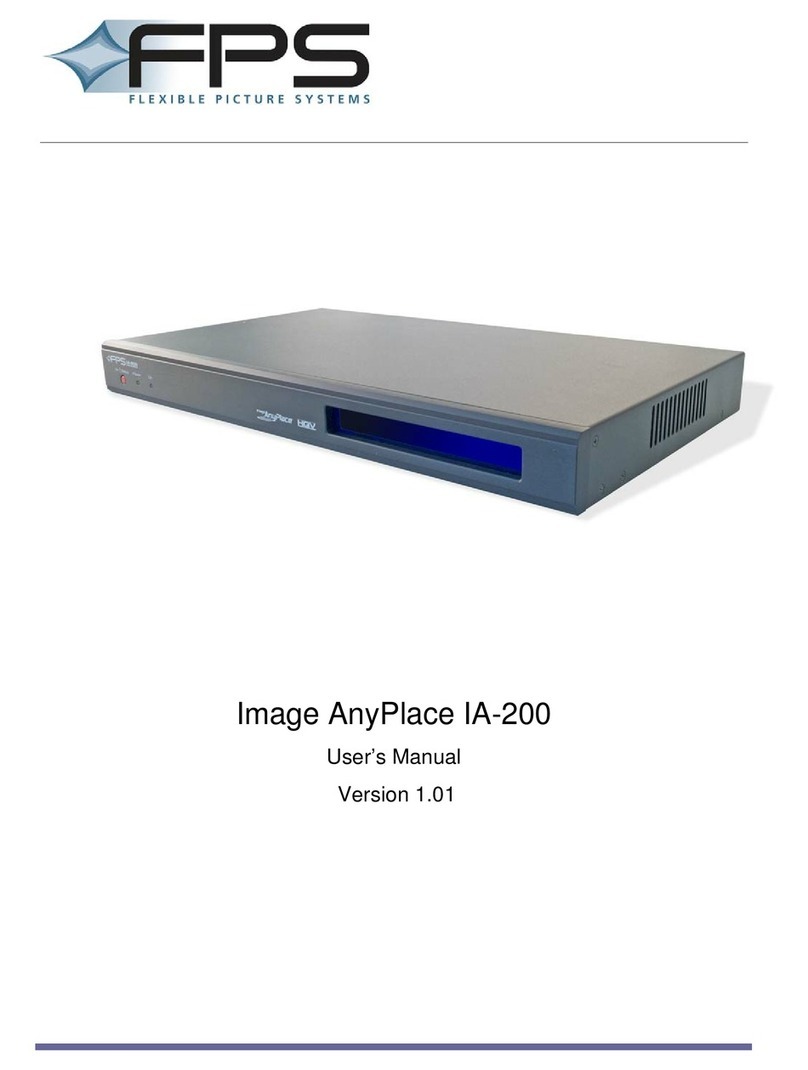
Extron electronics DVC 501 SD User manual

DVC 501 SD
SDI Converter
68-1518-01 Rev. A
07 11
User Guide
Signal Processors

ii
This symbol is intended to alert the user of important operating and
maintenance (servicing) instructions in the literature provided with the
equipment.
This symbol is intended to alert the user of the presence of uninsulated
dangerous voltage within the product enclosure that may present a risk of
electric shock.
Caution
2EAD)NSTRUCTIONSsRead and understand all safety and operating instructions before using the equipment.
2ETAIN)NSTRUCTIONSsThe safety instructions should be kept for future reference.
&OLLOW7ARNINGSsFollow all warnings and instructions marked on the equipment or in the user information.
!VOID!TTACHMENTSsDo not use tools or attachments that are not recommended by the equipment
manufacturer because they may be hazardous.
Warning
0OWERSOURCESsThis equipment should be operated only from the power source indicated on the product. This
equipment is intended to be used with a main power system with a grounded (neutral) conductor. The third
(grounding) pin is a safety feature; do not attempt to bypass or disable it.
0OWERDISCONNECTIONsTo remove power from the equipment safely, remove all power cords from the rear of
the equipment, the desktop power module (if detachable), or the power source receptacle (wall plug).
0OWERCORDPROTECTIONsPower cords should be routed so that they are not likely to be stepped on or pinched
by items placed upon or against them.
3ERVICINGsRefer all servicing to qualified service personnel. There are no user-serviceable parts inside. To prevent
the risk of shock, do not attempt to service this equipment yourself because opening or removing covers may
expose you to dangerous voltage or other hazards.
3LOTSANDOPENINGSsIf the equipment has slots or holes in the enclosure, these are provided to prevent
overheating of sensitive components inside. These openings must never be blocked by other objects.
,ITHIUMBATTERYsThere is a danger of explosion if battery is incorrectly replaced. Replace it only with the
same or equivalent type recommended by the manufacturer. Dispose of used batteries according to the
manufacturer instructions.
Ce symbole sert à avertir l’utilisateur que la documentation fournie avec le
matériel contient des instructions importantes concernant l’exploitation et la
maintenance (réparation).
Ce symbole sert à avertir l’utilisateur de la présence dans le boîtier
de l’appareil de tensions dangereuses non isolées posant des risques
d’électrocution.
Attention
,IRELESINSTRUCTIONSsPrendre connaissance de toutes les consignes de sécurité et d’exploitation avant
d’utiliser le matériel.
#ONSERVERLESINSTRUCTIONSsRanger les consignes de sécurité afin de pouvoir les consulter à l’avenir.
2ESPECTERLESAVERTISSEMENTSsObserver tous les avertissements et consignes marqués sur le matériel ou
présentés dans la documentation utilisateur.
%VITERLESPIÒCESDEFIXATIONsNe pas utiliser de pièces de fixation ni d’outils non recommandés par le
fabricant du matériel car cela risquerait de poser certains dangers.
Avertissement
!LIMENTATIONSsNe faire fonctionner ce matériel qu’avec la source d’alimentation indiquée sur l’appareil. Ce
matériel doit être utilisé avec une alimentation principale comportant un fil de terre (neutre). Le troisième
contact (de mise à la terre) constitue un dispositif de sécurité : n’essayez pas de la contourner ni de la
désactiver.
$ÏCONNEXIONDELALIMENTATIONsPour mettre le matériel hors tension sans danger, déconnectez tous les
cordons d’alimentation de l’arrière de l’appareil ou du module d’alimentation de bureau (s’il est amovible) ou
encore de la prise secteur.
0ROTECTIONDUCORDONDALIMENTATIONsAcheminer les cordons d’alimentation de manière à ce que personne
ne risque de marcher dessus et à ce qu’ils ne soient pas écrasés ou pincés par des objets.
2ÏPARATIONMAINTENANCEsFaire exécuter toutes les interventions de réparation-maintenance par un
technicien qualifié. Aucun des éléments internes ne peut être réparé par l’utilisateur. Afin d’éviter tout danger
d’électrocution, l’utilisateur ne doit pas essayer de procéder lui-même à ces opérations car l’ouverture ou le
retrait des couvercles risquent de l’exposer à de hautes tensions et autres dangers.
&ENTESETORIFICESsSi le boîtier de l’appareil comporte des fentes ou des orifices, ceux-ci servent à empêcher les
composants internes sensibles de surchauffer. Ces ouvertures ne doivent jamais être bloquées par des objets.
,ITHIUM"ATTERIEsIl a danger d’explosion s’ll y a remplacment incorrect de la batterie. Remplacer uniquement
avec une batterie du meme type ou d’un type equivalent recommande par le constructeur. Mettre au reut les
batteries usagees conformement aux instructions du fabricant.
3AFETY)NSTRUCTIONSs%NGLISH
#ONSIGNESDE3ÏCURITÏsFrançais
3ICHERHEITSANLEITUNGENs$EUTSCH
Dieses Symbol soll dem Benutzer in der im Lieferumfang enthaltenen
Dokumentation besonders wichtige Hinweise zur Bedienung und Wartung
(Instandhaltung) geben.
Dieses Symbol soll den Benutzer darauf aufmerksam machen, daß im Inneren
des Gehäuses dieses Produktes gefährliche Spannungen, die nicht isoliert sind
und die einen elektrischen Schock verursachen können, herrschen.
Achtung
Lesen der Anleitungen s"EVOR3IEDAS'ERËTZUMERSTEN-ALVERWENDENSOLLTEN3IEALLE3ICHERHEITSUND
"EDIENUNGSANLEITUNGENGENAUDURCHLESENUNDVERSTEHEN
Aufbewahren der Anleitungen s$IE(INWEISEZURELEKTRISCHEN3ICHERHEITDES0RODUKTESSOLLTEN3IE
AUFBEWAHRENDAMIT3IEIM"EDARFSFALLDARAUFZURàCKGREIFENKÚNNEN
Befolgen der Warnhinweise s"EFOLGEN3IEALLE7ARNHINWEISEUND!NLEITUNGENAUFDEM'ERËTODERINDER
"ENUTZERDOKUMENTATION
Keine Zusatzgeräte s6ERWENDEN3IEKEINE7ERKZEUGEODER:USATZGERËTEDIENICHTAUSDRàCKLICHVOM
(ERSTELLEREMPFOHLENWURDENDADIESEEINE'EFAHRENQUELLEDARSTELLENKÚNNEN
Vorsicht
Stromquellen s$IESES'ERËTSOLLTENURàBERDIEAUFDEM0RODUKTANGEGEBENE3TROMQUELLEBETRIEBENWERDEN
$IESES'ERËTWURDEFàREINE6ERWENDUNGMITEINER(AUPTSTROMLEITUNGMITEINEMGEERDETENNEUTRALEN,EITER
KONZIPIERT$ERDRITTE+ONTAKTISTFàREINEN%RDANSCHLUUNDSTELLTEINE3ICHERHEITSFUNKTIONDAR$IESESOLLTENICHT
UMGANGENODERAUER"ETRIEBGESETZTWERDEN
Stromunterbrechung s5MDAS'ERËTAUFSICHERE7EISEVOM.ETZZUTRENNENSOLLTEN3IEALLE.ETZKABELAUSDER
2àCKSEITEDES'ERËTESAUSDEREXTERNEN3TOMVERSORGUNGFALLSDIESMÚGLICHISTODERAUSDER7ANDSTECKDOSE
ziehen.
3CHUTZDES.ETZKABELSs.ETZKABELSOLLTENSTETSSOVERLEGTWERDENDASIENICHTIM7EGLIEGENUNDNIEMAND
DARAUFTRETENKANNODER/BJEKTEDARAUFODERUNMITTELBARDAGEGENGESTELLTWERDENKÚNNEN
7ARTUNGs!LLE7ARTUNGSMANAHMENSOLLTENNURVONQUALIlZIERTEM3ERVICEPERSONALDURCHGEFàHRTWERDEN
$IEINTERNEN+OMPONENTENDES'ERËTESSINDWARTUNGSFREI:UR6ERMEIDUNGEINESELEKTRISCHEN3CHOCKS
VERSUCHEN3IEINKEINEM&ALLDIESES'ERËTSELBSTÚFFNENDABEIM%NTFERNENDER!BDECKUNGENDIE'EFAHREINES
ELEKTRISCHEN3CHLAGSUNDODERANDERE'EFAHRENBESTEHEN
3CHLITZEUND¾FFNUNGENs7ENNDAS'ERËT3CHLITZEODER,ÚCHERIM'EHËUSEAUFWEISTDIENENDIESEZUR
6ERMEIDUNGEINERÄBERHITZUNGDEREMPlNDLICHEN4EILEIM)NNEREN$IESE¾FFNUNGENDàRFENNIEMALSVON
anderen Objekten blockiert werden.
,ITIUM"ATTERIEs%XPLOSIONSGEFAHRFALLSDIE"ATTERIENICHTRICHTIGERSETZTWIRD%RSETZEN3IEVERBRAUCHTE"ATTERIEN
NURDURCHDENGLEICHENODEREINENVERGLEICHBAREN"ATTERIETYPDERAUCHVOM(ERSTELLEREMPFOHLENWIRD
%NTSORGEN3IEVERBRAUCHTE"ATTERIENBITTEGEMËDEN(ERSTELLERANWEISUNGEN
Este símbolo se utiliza para advertir al usuario sobre instrucciones
importantes de operación y mantenimiento (o cambio de partes) que se
desean destacar en el contenido de la documentación suministrada con los
equipos.
Este símbolo se utiliza para advertir al usuario sobre la presencia de
elementos con voltaje peligroso sin protección aislante, que puedan
encontrarse dentro de la caja o alojamiento del producto, y que puedan
representar riesgo de electrocución.
Precaucion
,EERLASINSTRUCCIONESsLeer y analizar todas las instrucciones de operación y seguridad, antes de usar el
equipo.
#ONSERVARLASINSTRUCCIONESsConservar las instrucciones de seguridad para futura consulta.
/BEDECERLASADVERTENCIASsTodas las advertencias e instrucciones marcadas en el equipo o en la
documentación del usuario, deben ser obedecidas.
%VITARELUSODEACCESORIOSsNo usar herramientas o accesorios que no sean especificamente
recomendados por el fabricante, ya que podrian implicar riesgos.
Advertencia
!LIMENTACIØNELÏCTRICAs%STEEQUIPODEBECONECTARSEÞNICAMENTEALAFUENTETIPODEALIMENTACIØNELÏCTRICA
indicada en el mismo. La alimentación eléctrica de este equipo debe provenir de un sistema de distribución
general con conductor neutro a tierra. La tercera pata (puesta a tierra) es una medida de seguridad, no
puentearia ni eliminaria.
$ESCONEXIØNDEALIMENTACIØNELÏCTRICAsPara desconectar con seguridad la acometida de alimentación
eléctrica al equipo, desenchufar todos los cables de alimentación en el panel trasero del equipo, o desenchufar
el módulo de alimentación (si fuera independiente), o desenchufar el cable del receptáculo de la pared.
0ROTECCIØNDELCABLESDEALIMENTACIØNsLos cables de alimentación eléctrica se deben instalar en lugares
donde no sean pisados ni apretados por objetos que se puedan apoyar sobre ellos.
2EPARACIONESYMANTENIMIENTOs3OLICITARSIEMPRELOSSERVICIOSTÏCNICOSDEPERSONALCALIlCADO%NELINTERIOR
no hay partes a las que el usuario deba acceder. Para evitar riesgo de electrocución, no intentar personalmente
la reparación/mantenimiento de este equipo, ya que al abrir o extraer las tapas puede quedar expuesto a
voltajes peligrosos u otros riesgos.
2ANURASYABERTURASsSi el equipo posee ranuras o orificios en su caja/alojamiento, es para evitar el
SOBRECALIENTAMIENTODECOMPONENTESINTERNOSSENSIBLES%STASABERTURASNUNCASEDEBENOBSTRUIRCONOTROS
objetos.
"ATERÓADELITIOs%XISTERIESGODEEXPLOSIØNSIESTABATERÓASECOLOCAENLAPOSICIØNINCORRECTA#AMBIARESTA
BATERÓAÞNICAMENTECONELMISMOTIPOOSUEQUIVALENTERECOMENDADOPORELFABRICANTE$ESACHARLASBATERÓAS
usadas siguiendo las instrucciones del fabricante.
)NSTRUCCIONESDESEGURIDADs%SPA×OL
安全须知 s 中文
这个符号提示用户该设备用户手册中有重要的操作和维护说明。
这个符号警告用户该设备机壳内有暴露的危险电压,有触电危险。
注意
阅读说明书 s用户使用该设备前必须阅读并理解所有安全和使用说明。
保存说明书 s用户应保存安全说明书以备将来使用。
遵守警告 s用户应遵守产品和用户指南上的所有安全和操作说明。
避免追加 s不要使用该产品厂商没有推荐的工具或追加设备,以避免危险。
警告
电源 s该设备只能使用产品上标明的电源。 设备必须使用有地线的供电系统供电。 第三条线(
地线)是安全设施,不能不用或跳过 。
拔掉电源 s为安全地从设备拔掉电源,请拔掉所有设备后或桌面电源的电源线,或任何接到市电
系统的电源线。
电源线保护 s妥善布线, 避免被踩踏,或重物挤压。
维护 s 所有维修必须由认证的维修人员进行。 设备内部没有用户可以更换的零件。为避免出现触
电危险不要自己试图打开设备盖子维修该设备。
通风孔 s有些设备机壳上有通风槽或孔,它们是用来防止机内敏感元件过热。 不要用任何东西
挡住通风孔。
锂电池 s不正确的更换电池会有爆炸的危险。必须使用与厂家推荐的相同或相近型号的电池。按
照生产厂的建议处理废弃电池。
iii
FCC Class A Notice
This equipment has been tested and found to comply with the limits for a Class A digital device, pursuant to part 15
of the FCC Rules. Operation is subject to the following two conditions:
1. This device may not cause harmful interference.
2. This device must accept any interference received, including interference that may cause undesired operation.
The Class A limits are designed to provide reasonable protection against harmful interference when the equipment
is operated in a commercial environment. This equipment generates, uses, and can radiate radio frequency energy
and, if not installed and used in accordance with the instruction manual, may cause harmful interference to radio
communications. Operation of this equipment in a residential area is likely to cause harmful interference, in which
case the user will be required to correct the interference at his own expense.
NOTE: This unit was tested with shielded cables on the peripheral devices. Shielded cables must be used with
the unit to ensure compliance with FCC emissions limits.
&ORMOREINFORMATIONONSAFETYGUIDELINESREGULATORYCOMPLIANCES%-)%-&COMPLIANCEACCESSIBILITYAND
related topics, click here.

iv
Conventions Used in this Guide
In this user guide, the following conventions are used:
NOTE: A note draws attention to important information.
TIP: A tip provides a suggestion to make working with the device easier.
CAUTION: A caution indicates a potential hazard to equipment or data.
WARNING: A warning warns of things or actions that might cause injury, death, or
other severe consequences.
Commands are written in the fonts shown here:
^AR Merge Scene,,Op1 scene 1,1 ^B 51 ^W^C
[01] R 0004 00300 00400 00800 00600 [02] 35 [17] [03]
E
X!*X1&*
X2)*
X2#*
X2!CE}
NOTE: For commands and examples of computer or device responses mentioned
in this guide, the character “0” is used for the number zero and “O”
represents the capital letter “o.”
Computer responses and directory paths that do not have variables are written in the font
shown here:
Reply from 208.132.180.48: bytes=32 times=2ms TTL=32
C:\Program Files\Extron
6ARIABLESAREWRITTENINSLANTEDFORMASSHOWNHERE
ping xxx.xxx.xxx.xxx —t
SOH R Data STX Command ETB ETX
Selectable items, such as menu names, menu options, buttons, tabs, and field names are
written in the font shown here:
From the File menu, select New.
Click the OK button.
Copyright
¥%XTRON%LECTRONICS!LLRIGHTSRESERVED
Trademarks
All trademarks mentioned in this guide are the properties of their respective owners.

v$6#3$s#ONTENTS
Contents
Introduction............................................................ 1
!BOUTTHIS'UIDE ................................................ 1
!BOUTTHE$6#3$#ONVERTER....................... 1
Features.............................................................. 1
Application Diagram ........................................... 2
Installation.............................................................. 3
Installation Overview........................................... 3
Rear Panel........................................................... 4
Connecting for Remote Control.......................... 5
Connecting to the RS-232 Port ....................... 5
#ONNECTINGTOTHE53"#ONFIG0ORT................. 6
Operation................................................................ 9
Front Panel ......................................................... 9
Powering On..................................................... 10
Default Cycle ................................................ 10
Default Cycle — Special Conditions .............. 10
Menus on the LCD Screen................................. 11
Menu System Overview................................. 11
Output Configuration Menu ......................... 13
Audio Config Menu ...................................... 14
Advanced Config Menu ................................ 15
%XITINGTHE-ENU3YSTEM............................... 16
Resetting ......................................................... 16
&RONT0ANEL,OCKOUT%XECUTIVE-ODE............... 17
5PDATING&IRMWARE ........................................... 17
Remote Configuration and Control ................ 21
Communication Ports ....................................... 21
5SING3)3#OMMANDS........................................ 21
$6#INITIATED-ESSAGES ................................ 21
%RROR2ESPONSES............................................. 22
5SINGTHE#OMMANDAND2ESPONSE4ABLE...... 22
Symbol Definitions ........................................ 23
Command and Response Table ......................... 24
Reference Information....................................... 26
Specifications.................................................... 26
Part Numbers and Accessories........................... 29
Included Parts ............................................... 29
Optional Accessories ..................................... 29
-OUNTINGTHE$6#3$#ONVERTER............... 29
Rack Mounting ............................................. 29
5NDERDESK-OUNTING ................................... 30
Through-desk Mounting ............................... 31

$6#3$s#ONTENTS vi

$6#3$s)NTRODUCTION 1
Introduction
4HISSECTIONGIVESANOVERVIEWOFTHE%XTRON$6#3$$IGITAL6IDEO#ONVERTER4OPICS
include:
s About this Guide
s About the DVC 501 SD Converter
s Features
s Application Diagram
About this Guide
This guide provides information for experienced installers on how to install, configure, and
OPERATETHE$6#3$CONVERTER
)NTHISGUIDETHETERMSh$6#vh$6#3$vANDhCONVERTERvAREUSEDINTERCHANGEABLY
TOREFERTOTHE$6#3$CONVERTER
About the DVC 501 SD Converter
4HE%XTRON$6#3$ISADIGITALVIDEOCONVERTERTHATRECEIVES3$)($3$)AND'3$)
SERIALDIGITALVIDEOSIGNALSANDCONVERTSTHEMTO$6)$ANDANALOG2'"ORCOMPONENTVIDEO
)TISCOMPLIANTWITH3-04%---AND)45DIGITALVIDEOSTANDARDS4HE2'"
OUTPUTCANBESETFOR2'"(62'"3AND2'S""ILEVELORTRILEVELSYNCCANBESELECTEDWHEN
the unit is set for component video output.
4HE$6#3$CONVERTERISPARTICULARLYSUITEDTOAPPLICATIONSSUCHASTELEVISIONPRODUCTION
medical imaging, and live events that require interfacing of SDI signals from broadcast-type
sources to professional and consumer-level displays and signal distribution systems that
ACCEPTONLY$6)ORANALOGSIGNALS
Features
4HE$6#3$PROVIDESTHEFOLLOWINGFEATURES
s Input&EMALE".#CONNECTORWITHBUFFEREDLOOPTHROUGHFORMULTIRATE3$)SIGNALS
s Outputs$6)$ANDPIN($CONNECTORSFORDIGITALANDANALOG2'"ORCOMPONENT
video; a captive screw connector for balanced and unbalanced stereo audio
s Multi-rate SDI signals up to 2.97 Gbps accepted — Accepts data rates from
STANDARDDEFINITION.43#AND0!,TO($46P)TCOMPLIESWITH3-04%-
--AND)45DIGITALVIDEOSTANDARDS
s Simultaneous DVI-D and analog RGB or component video outputs — Provides
high resolution digital and analog video outputs that allow for easy integration of
MULTIRATE3$)SIGNALSINTO$6)OR2'"BASED!6DEVICESANDSYSTEMS
s AES3 audio de-embedding%XTRACTSANDOUTPUTSEMBEDDED!%3STEREOAUDIO
streams. Audio can be balanced or unbalanced.
s Balanced or unbalanced audio output
s Audio attenuation control

$6#3$s)NTRODUCTION 2
s Analog RGB or component video output/UTPUTSANALOG2'"AS2'"(62'"3
OR2'S"/UTPUTSCOMPONENTVIDEOAS29"99
s Buffered loop-through connector — A buffered input loop-through delivers reshaped
and restored multi-rate SDI signals.
s Bi-level or tri-level sync is available for component video output.
s Internal test patterns for calibration and setup — Nine test patterns are available,
including a crop pattern, color bars, and grayscale.
s Muting control — Provides video and audio output muting.
s RS-232 configuration and control — An RS-232 serial port provides configuration and
CONTROLVIATHE%XTRON3IMPLE)NSTRUCTION3ET3)3©COMMANDS
s USB configuration and control!53"#ONFIGPORTPROVIDESCONFIGURATIONAND
control via SIS commands.
s Front panel security lockout — Locks out all front panel functions except for input
SELECTIONALLFUNCTIONSREMAINAVAILABLETHROUGH23OR53"CONTROL
s Rack and furniture mountable 1U, half rack width metal enclosure
s Internal universal power supply4HE6!#(ZINTERNATIONALPOWER
supply provides worldwide power compatibility.
Application Diagram
4HEFOLLOWINGDIAGRAMSHOWSANEXAMPLEOFA$6#3$APPLICATION
100-240V ~ 0.5A MAX
50/60 Hz
SDI / HD-SDI
BUFFERED
INPUT
LOOP-THROUGH RGB/R-Y,Y, B-Y
OUTPUT
DVI-D
LR
RS-232
N/A Tx Rx
AUDIO
Extron
DVC 501 SD
SDI/HD-SDI to DVI and
RGB/YUV Converter
HDTV CameraVideo Capture
Flat Panel Display
HD Projector
Extron
XPA 1002
Power
Amplier
Extron
SI 28
Surface-mount
Speakers
RGBHV
DVI
HD-SDI
HD-SDI
XPA1002
12
LIMITER/PROTECT
SIGNAL
OVER
TEMP
Figure 1. Connection Diagram for a DVC 501 SD

$6#3$s)NSTALLATION 3
Installation
4HISSECTIONGIVESANOVERVIEWOFTHESTEPSFORINSTALLINGTHE$6#3$)TALSOPROVIDESA
description of the rear panel connectors and instructions for cabling. Topics include:
s Installation Overview
s Rear Panel
s Connecting for Remote Control
Installation Overview
CAUTION: Installation and service must be performed by authorized personnel only.
&OLLOWTHESESTEPSTOINSTALLANDSETUPTHE$6#3$
1. Disconnect power from the converter and ensure that all other devices that will be
connected to it are powered off.
2. (Optional) Mount the unit in a rack or to furniture (see “Mounting the
DVC 501 SD Converter” in the “Reference Information” section).
3. Connect the input.#ONNECTAN3$)($3$)OR'3$)SOURCETOTHE'($3$3$)
)NPUT".#CONNECTORbin figure 2 on the next page).
4. (Optional) Connect a monitor or recording device. Attach a monitor or a video
RECORDINGDEVICETOTHE"UFFERED,OOPTHROUGH)NPUT".#CONNECTORcin figure 2).
5. Connect the video output. Connect a display or other output device to one of the
following connectors:
s DVD-D — Digital video (din figure 2)
s RGB/R-Y,Y,B-Y!NALOG2'"2'"(62'"3AND2'S"OR956COMPONENTVIDEO
(ein figure 2)
6. Connect the audio output. Connect an amplifier or other audio output device to the
5-pole captive screw audio connector (fin figure 2).
7. Connect a control device. Connect a computer or control system to one of the
FOLLOWING$6#PORTSTOCONFIGUREANDCONTROLTHECONVERTERVIA3)3COMMANDS
s Config port (front panel)53"CONNECTIONain figure 9, “Operation”
section)
s RS-232 port (rear panel) — Serial RS-232 connection (gin figure 2)
NOTE: See “Command and Response Table” in the “Remote Configuration
and Control” section for definitions of the SIS commands.
8. 0LUGASTANDARD)%#POWERCORDPROVIDEDINTOTHEPOWERRECEPTACLEain the diagram
ONTHENEXTPAGE#ONNECTTHE$6#TOATO6!#(Z!#POWERSOURCE
9. #ONFIGURETHE$6#3$ASNEEDEDUSINGTHEFRONTPANELMENUSSEEhMenus on
the LCD Screen” in the “Operation” section) or SIS commands (see the “Remote
Configuration and Control” section).

$6#3$s)NSTALLATION 4
Rear Panel
4HEILLUSTRATIONBELOWSHOWSTHECONNECTORSONTHE$6#3$REARPANEL
CAUTION: 5SEELECTROSTATICDISCHARGEPRECAUTIONSBEELECTRICALLYGROUNDEDWHEN
MAKINGCONNECTIONS%LECTROSTATICDISCHARGE%3$CANDAMAGEEQUIPMENT
although you may not feel, see, or hear it.
WARNING: Remove power from the system before making any connections.
100-240V ~ 0.3A MAX
50/60 Hz
3G/HD/SD-SDI
BUFFERED
INPUT
LOOP-THROUGH RGB/R-Y,Y,B-Y
OUTPUT
DVI-D
LR
RS-232
N/A Tx Rx
AUDIO
12456
3
7
Figure 2. DVC 501 SD Rear Panel
aAC power connector 0LUGASTANDARD)%#POWERCORDINTOTHISMALE)%#CONNECTOR
TOCONNECTTHE$6#TOATO6!#(ZOR(ZPOWERSOURCE
b3G/HD/SD-SDI connector#ONNECTA'($3$)OR3$3$)SOURCETOTHISFEMALE
".#INPUTCONNECTOR
cBuffered loop-through 4HISFEMALE".#INPUTCONNECTORPASSESABUFFERED'
($3$)OR3$3$)SIGNALTHROUGHTOAMONITORORAVIDEOSTORAGEDEVICE
dDVI-D output connector#ONNECTA$6)OUTPUTDEVICETOTHISFEMALESINGLELINK
$6))CONNECTORONLYTHEDIGITALPINSAREENABLED2'"OR956COLORSPACEISAVAILABLE
on this buffered output. The following table shows the pin assignments for this
connector.
8Not used 16 Hot plug detect 24 TMDS clock–
Pin Signal Pin Signal Pin Signal
1TMDS data 2– 9TMDS data 1– 17 TMDS data 0–
2TMDS data 2+ 10 TMDS data 1+ 18 TMDS data 0+
3Ground (2/4 ) 11 Ground (1/3) 19 Ground (0/5)
4Not used 12 Not used 20 Not used
5Not used 13 Not used 21 Not used
6DDC clock 14 +5 V power 22 Ground (clock)
7DDC data 15 Ground (for 5 V) 23 TMDS clock+
18
17 24
9
Figure 3. DVI-D Connector Pin Assignments
eRGB/YUV output connector#ONNECTAN2'"2'"(62'"32'S"OR956
COMPONENT299"9DISPLAYDEVICETOTHISFEMALEPIN($CONNECTOR2'"OR956
color space is available on this buffered output.

$6#3$s)NSTALLATION 5
fAudio output connector — Connect an audio device to this female 5-pole 3.5 mm
CAPTIVESCREWCONNECTORFORBALANCEDORUNBALANCEDANALOGAUDIOOUTPUT7IRETHE
connector as shown below.
Do not tin the wires!
Balanced Audio Output
Tip
Ring
Tip
Ring
LR
Sleeves
Unbalanced Audio Output
Tip
Tip
LR
Sleeves
Figure 4. Audio Output Connector Wiring
CAUTIONS:s The length of the exposed wires in the stripping process is critical.
The ideal length is 3/16 inches (5 mm). If the exposed portion is
longer, the wires may touch, causing a short circuit between them. If
the exposed wires are shorter, they can be easily pulled out, even if
tightly fastened by the captive screws.
sDo not tin the wires. Tinned wire does not hold its shape and can
become loose over time.
sFor unbalanced audio, connect the sleeves to the ground contact.
DO NOT connect them to negative (–) contacts.
gRS-232 connector — Connect a host device such as a computer or touch panel control
system to the Tx, Rx, and _(ground) pins of this 5-pole captive screw connector for
SERIALCONTROLOFTHE$6#BY3)3COMMANDSSEEhConnecting to the RS-232 Port,”
below, for information on wiring this port). The first and second pins of this connector
are not used.
The default protocol for this port is 9600 baud, 1 stop bit, no parity, and no flow
control.
Connecting for Remote Control
Connecting to the RS-232 Port
4OCONNECTYOURCOMPUTERORCONTROLSYSTEMTOTHE$6#REARPANEL23PORTUSEAN
%XTRON5NIVERSAL#ONTROLCABLE5#gOR5#gSEEhOptional Accessories” in the
“Reference Information” section for part numbers) or other female 9-pin-to-bare-wire
RS-232 cable.
1. 7IRETHEUNTERMINATEDENDOFTHE23CABLETOTHEPOLECAPTIVESCREWCONNECTOR
PROVIDEDWITHTHE$6#ASFOLLOWS
a. Connect the transmit wire to the middle pin, which plugs into the Tx (transmit) port.
b. Connect the receive wire to the fourth pin, which plugs into the Rx (receive) port.
c. Connect the ground wire to the last pin, which plugs into the ground port, marked
with _.
2. Plug the cable into the RS-232 portion of the 5-pole captive screw connector on the
$6#REARPANEL
See the illustration on the next page.

$6#3$s)NSTALLATION 6
RS-232
Computer or
Control System
RS-232 Port
DVC 501 SD or
Rear Panel
RS-232 Port
NOTE: If you use cable that has a drain
wire, tie the drain wire to ground
at both ends.
Tx Rx
NOTE: Connect a ground wire between the DVC
and the computer or control system.
1 2 3
N/A
Ground ( )
Transmit (Tx)
Receive (Rx) Transmit (Tx)
Receive (Rx)
Figure 5. Connecting to the RS-232 Port
In the “Remote Configuration and Control” section, see “Using SIS Commands” for
information on sending SIS commands to this port.
Connecting to the USB Config Port
4HEMINI4YPE"53"#ONFIGPORTISLOCATEDONTHE$6#FRONTPANEL)TCANBEUSEDTO
configure the converter via SIS commands.
1. 5SEA53"!TOMINI"CABLETOCONNECTTHE$6#53"#ONFIGPORTTOA53"PORTONYOUR
computer.
USB Cable
Type A
USB
Mini Type B
USB USB 1
USB
Ports
Computer
Converter Front Panel
Extron
NEXT
MENU
DVC SERIES
DIGITAL VIDEO CONVERTER
ADJUST
CONFIG
Figure 6. Connecting to the Config Port

$6#3$s)NSTALLATION 7
2. )FTHISISTHEFIRSTTIMEYOUHAVECONNECTEDA$6#3$TOTHISPARTICULAR53"PORTON
YOURCOMPUTERTHE&OUND.EW(ARDWARE7IZARDOPENS/NTHEFIRSTSCREENSPECIFY
WHETHERYOUWANTTHECOMPUTERTOCONNECTTO7INDOWS®5PDATEINORDERTOSEARCHTHE
WEBFORTHEDRIVERTHATITNEEDSTOCOMMUNICATEWITHTHE$6#VIATHE53"PORTTHISIS
NOTNECESSARYIFTHE53"DRIVERALREADYEXISTSONYOURCOMPUTER
Figure 7. Found New Hardware Wizard Opening Screen
s Select the Yes, this time only radio button if you want your computer to
CONNECTTO7INDOWS5PDATEONLYTHISONETIME
s Select Yes, now and every time Iconnect adevice if you want the computer to
AUTOMATICALLYCONNECTTO7INDOWS5PDATEEVERYTIMETHE$6#ISCONNECTEDTOTHIS
53"PORT
s Select No, not this timeIFYOUDONOTWANTTHECOMPUTERTOCONNECTTO7INDOWS
5PDATEATTHISTIMEFOREXAMPLEIFTHEDRIVERISALREADYONYOURCOMPUTER

$6#3$s)NSTALLATION 8
3. Click Next. On the next screen, make sure that the Install the software
automatically (Recommended) radio button is selected, then click Next (you do not
need to insert a disc).
Figure 8. Selecting the Radio Button to Install the USB Driver Automatically
9OURCOMPUTERLOCATESTHEDRIVERNEEDEDFORITTOCOMMUNICATEWITHTHE$6#3$VIA
THE53"PORT
4. 7HENTHE#OMPLETEDSCREENAPPEARSCLICKFinish to close the wizard.
NOTE: This wizard appears only the firstTIMEYOUCONNECTTHE$6#TOEACH53"
PORT9OUDONOTSEETHEWIZARDAGAINUNLESSYOUCONNECTTHE$6#TOA
DIFFERENT53"PORTONYOURCOMPUTER
5. #ONFIGURETHE$6#ASDESIREDUSING3)3COMMANDSSEETHEhUsing SIS Commands”
section for more information).

$6#3$s/PERATION 9
Operation
This section discusses the functions available through the front panel to set up and operate
THE$6#3$4OPICSINCLUDE
s Front Panel
s Powering On
s Menus on the LCD Screen
s Resetting
s Front Panel Lockout (Executive Mode)
s Updating Firmware
Front Panel
CONFIG
NEXT
MENU
DVC 501 SD
DIGITAL VIDEO CONVERTER
ADJUST
1235
4
Figure 9. DVC 501 SD Front Panel
The front panel features and controls shown in the illustration above are described starting
below.
aConfig port#ONNECTA53"CABLE53"!TOMINI"FROMYOURCOMPUTERTOTHISPORT
TOCONFIGUREANDCONTROLTHE$6#VIA3)3COMMANDSANDTOUPDATETHEFIRMWARE
bLCD screen — Displays menus, messages, and your selections from menus and
submenus (see “Menus on the LCD Screen,” later in this section, for more
information).
cMenu button0RESSTHISBUTTONTOACCESSTHE$6#MENUSYSTEMANDSTEPTHROUGH
the menus displayed on the LCD screen (b) (see “Menus on the LCD Screen” for
details).
dNext button — Press this button to step through the submenus displayed on the LCD
screen.
eAdjust knobs — Rotate these horizontal ([) and vertical ({) knobs to scroll through
submenu options and make adjustments.

$6#3$s/PERATION 10
Powering On
!PPLYPOWERBYCONNECTINGTHEPROVIDED)%#POWERCORDTOTHEREARPANELPOWERCONNECTOR
ONTHE$6##ONNECTTHE$6#TOAN!#POWERSOURCE
NOTE: Audio and video mute settings are not retained when power is cycled to the
$6#
Default Cycle
7HENPOWERISAPPLIEDTHE,#$SCREENDISPLAYSTHE%XTRON33logo. After approximately
10 seconds, EXTRON DVC 501 SD is displayed. The unit part number and current firmware
version are displayed after approximately another 5 seconds. After those screens, the default
cycle begins, in which the LCD screen alternates every 5 seconds between the input signal
type and data rate, and the output resolution and refresh rate. The default cycle continues
while the menu system is not in use.
The flow diagram below shows the order in which the screens appear at power-up and
during the default cycle.
60-1033-01
F/W V1.00
5 sec.
5 sec.
EXTRON
DVC 501 SD
5 sec.
5 sec.
Power
On
10 sec.
INPUT
HDSDI 1.485G
INPUT
720p @59.94Hz
Figure 10. Power-up and Normal Default Cycle Example
Default Cycle — Special Conditions
The default cycle changes when any of the following conditions exist:
s No input connected — A single screen is displayed, indicating that there is no input
signal.
INPUT
NO SIGNAL!
Figure 11. Default Screen When No Input Is Connected

$6#3$s/PERATION 11
s Overheating — The Temperature Overload!!! screen is added to the default cycle if
the internal temperature of the unit exceeds 65 °C (149 °F).
TEMPERATURE
OVERLOAD!!!
INPUT
HDSDI 1.485G
INPUT
720p @59.94Hz
5 sec.
5 sec.
5 sec.
Figure 12. Example of the Default Cycle When the Unit Is Overheating
s Video muted — The input resolution and rate screen (second screen of the default
cycle) displays a blinking asterisk (*) on both sides of the word INPUT. The asterisks
disappear when the video is unmuted (the asterisks also appear on the INPUT NO
SIGNAL! screen during video muting.)
INPUT
HDSDI 1.485G
* INPUT *
720p @59.94Hz
5 sec.
5 sec.
Figure 13. Example of the Default Cycle When the Video Is Muted
To mute and unmute the video, see the Video Mute SIS commands in the “Remote
Configuration and Control” section.
Menus on the LCD Screen
4HE$6#3$MENUSTHATAREDISPLAYEDONTHE,#$SCREENENABLEYOUTOCONFIGURE
and operate the converter. The menu navigation buttons (Menu and Next) are located to
the right of the LCD screen. Press these buttons to cycle through the available menus and
submenus, and use the horizontal and vertical Adjust knobs to select options.
This section provides information on the menus and submenus, including any procedures
that are initiated from them.
Menu System Overview
The menu system consists of three menus, which have submenus that enable you to make
desired adjustments (see the menu flow diagram on the next page).
Using the menus
1. To access the menu system, press the Menu button. The first menu (OUTPUT CONFIG) is
displayed on the LCD screen.
2. Select other menus by repeatedly pressing the Menu button until the desired menu is
displayed.
3. Press the Next button repeatedly to cycle through the submenus for the selected menu.
4. 7HENTHEDESIREDSUBMENUISDISPLAYEDROTATETHEHORIZONTAL[) or vertical ({) Adjust
knob clockwise or counterclockwise to cycle through the submenu options. If you want
to return to a menu from within one of its submenus, press Menu.
5. 7HENTHEDESIREDOPTIONISDISPLAYEDDOONEOFTHEFOLLOWINGTOSELECTIT
s Press Next to display another submenu.
s Press Menu repeatedly until the EXIT MENU PRESS NEXT screen appears, then press
the Next button to return to the default cycle.
s 7AITUNTILTHE,#$SCREENRETURNSTOTHEDEFAULTCYCLEAPPROXIMATELYSECONDS

$6#3$s/PERATION 12
NOTE: The menus time out and the default cycle is displayed after 30 seconds of
inactivity; however, any selections you made with the Adjust knobs are saved
and remain in effect until you change them or reset the unit to factory defaults
(see “Resetting,” later in this section).
Menu flow diagram
The flow diagram below shows the menus that are displayed in the front panel LCD screen
and the order in which they appear when you repeatedly press the Menu button.
AUDIO
CONFIG
Menu
Menu
30 sec.
Default
Cycle
Menu
Next
EXIT MENU
PRESS NEXT
OUTPUT
CONFIG 30 sec.
30 sec.
Menu
ADVANCED
CONFIG
30 sec.
Menu
Figure 14. Main Menu Flow Diagram

$6#3$s/PERATION 13
Output Configuration Menu
The output configuration menu allows you to set the output resolution and refresh rate, the
OUTPUTSIGNALTYPEANDTHESYNCPOLARITY2'"(6ONLY4HEFOLLOWINGFLOWDIAGRAMSHOWS
the output configuration submenus and the adjustments that can be made from them.
OUTPUT
CONFIG
FORMAT
RGBHV
H SYNC V
POS POS
Next
Select the signal format:
RGBHV (default)
RGBS
RGsB
YUV Bi-Level
YUV Trilevel
Next
Use either Adjust knob to
select a submenu option.
Select the sync polarity
combination (Horizontal
and Vertical):*
Neg Neg
Neg Pos
Pos Neg
Pos Pos (default)
Default
Cycle
Menu
Next
*This screen appears only if
RGBHV is selected for the format.
Figure 15. Output Configuration Menu
4HEOUTPUTFORMATANDSYNCPOLARITYCANBECONFIGUREDFORBOTHTHEANALOGAND$6)
OUTPUTS4HECOLORSPACEAFFECTSBOTHOUTPUTSANDTHESYNCPOLARITYISTRANSMITTEDINTHE$6)
information frame for the display to interpret if necessary.
Format submenu
Rotate either the horizontal ([) or the vertical ({) Adjust knob to select the output video
FORMATREQUIREDBYTHEDISPLAY!VAILABLESIGNALTYPESARE2'"(6DEFAULT2'"32'S"
956BILEVELAND956TRILEVEL
NOTE: 3ETTINGTHESYNCFORMATTO956BILEVELANDTRILEVELALSOAFFECTSTHECOLORSPACEOFTHE
$6)OUTPUT
Sync Polarity submenu
4HEDISPLAYDEVICEMAYREQUIREAPARTICULARCOMBINATIONOFHORIZONTAL(ANDVERTICAL6SYNC
SIGNALPOLARITIES3ELECTTHEAPPROPRIATECOMBINATIONOFPOSITIVEORNEGATIVE(AND6SYNCBY
rotating either the horizontal ([) or vertical ({) Adjust knob. Options are H-V-, H+V-, H-V+,
or H+V+ (default).
Resolutions and refresh rates
The output resolution and refresh rate follow those of the source device. The table below
SHOWSTHERESOLUTIONSANDREFRESHRATESONTHE$6#3$
Resolution/
Rate 23.98 Hz 24 Hz 25 Hz 29.97 Hz 30 Hz 50 Hz 59.94 Hz 60 Hz
720p X X X X X X
I X X X
P X X X X X X X X
NTSC X
PAL X

$6#3$s/PERATION 14
Audio Config Menu
The Audio Config menu enables you to adjust the level of attenuation, mute and unmute
the audio, and select the pair of audio channels on which to extract the audio from the
3G-SDI, HD-SDI, or SD-SDI signal. The flow diagram below shows the audio configuration
submenus and the adjustments that can be made from them.
AUDIO
CONFIG Next
AUDIO MUTE
DISABLED
GAIN/ATTEN
0 dB
Next
Menu
Mute or unmute the audio.
DISABLED (Default)
ENABLED
OUTPUT
CONFIG
Next
Tu rn either Adjust knob
to select a setting.
DECODE AUDIO
ON PAIR <1>
Select an audio pair to
extract.
Range: 1through 8
Default: 1
Set the audio attenuation
for the selected input.
Range: -18 through 0dB
Default: 0
Figure 16. !UDIO#ONFIG-ENU
Audio Mute submenu
From this submenu you can mute or unmute the audio. Rotate either Adjust knob to select
Enabled to mute the audio or Disabled to unmute it.
Gain/Atten submenu
9OUCANSETONLYTHEATTENUATIONLEVELFROMTHISSUBMENU To set the attenuation,
rotate either Adjust knob to the RIGHT to DECREASE the attenuation and to the LEFT to
INCREASE it (-18 through 0dB). The default is 0dB.
Decode Audio on Pair <N> submenu
On this screen, you can select the channel pair on which the embedded audio will be
extracted and output onto the 5-pole captive screw audio connector. Rotate either Adjust
knob until the desired channel pair number (1through 8) is displayed within the angle
brackets.
DECODE AUDIO
ON PAIR <1>
Figure 17. %XAMPLEOFA$ECODE!UDIOON0AIRN,#$3UBMENU
Other manuals for DVC 501 SD
2
Table of contents
Other Extron electronics Signal Processor manuals

Extron electronics
Extron electronics USP 507 User manual

Extron electronics
Extron electronics Active Audio AAP User manual

Extron electronics
Extron electronics MGP 641 xi Series User manual

Extron electronics
Extron electronics MGP Pro Series User manual

Extron electronics
Extron electronics MGP Pro Series User manual

Extron electronics
Extron electronics MGP 641 User manual

Extron electronics
Extron electronics DVS 605 User manual

Extron electronics
Extron electronics USP 405 User manual

Extron electronics
Extron electronics USP 405 User manual

Extron electronics
Extron electronics Annotator 401 User manual