Eye Lighting Iwasaki Electric ESS0460-H119 User manual

F08-064
Operating Manual
ESS0460-H119
PV Module Solar Soaking Chamber
12/19/2008

Thank you for your purchase. We are confident you will be completely satisfied with your new system. If
for any reason you need assistance, please contact us:
EYE Lighting International / Iwasaki Electric
9150 Hendricks Road
Mentor, OH 44060
888-665-2677
support@eyeappliedoptics.com
In order to operate this system properly and prevent potential problems, please read the following
operation instructions.
Table of Contents
1. System Components
2. Installation
3. Control Panel
4. System Operation
5. Solar Lamps
6. Irradiation Intensity Control
7. Troubleshooting

1. System Components:
①Solar Lighting Array Housing – (60) 400W solar lamp array
②Solar Lamp Power / Inverter Cabinet – includes (5) inverter units (12 modules per unit;
one module per lamp) and solar lamp starters (60 units; one starter per lamp)
③Operation Control Panel – control and failure alert
④Main Power Breaker – 3 phase main power switch for system
⑤Solar Light Chamber Shields – roll down curtains to shield excess light from work area
⑥Solar Irradiation Chamber
⑦Cooling Air Ducts – dual axial blowers direct air over PV panels under test
⑧PV Panel Support Trays – interchangeable; (4) separate frames for standard thin-film
modules (60cm x 120cm) and (4) free-format frames for all other size PV modules; trays
provide for easy insertion of PV panels and allow cooling air to flow above and below
panels

2. Installation
A. When installing this chamber, please avoid placing it in any area where corrosive gas or
explosive gas is present. It is also highly recommended that the area be as dust free as
possible with controlled humidity.
B. The chamber should be placed as close to the mains power source (power transformer)
and mains breaker as possible.
C. Due to the heat generated by the solar array, keep flammable materials away from the
top of the chamber.
D. Please refer to the following diagrams to ensure proper clearance around the chamber
for proper operation and maintenance / inspection
Electrical / Power Characteristics
System Power: 3 Ø; 208V AC; 60Hz; 35kVA (approximately 100 A)
Cooling Blower Fans: 0.75 kW × 2 units
Solar Lamps: 208V; 400W × 60 lamps
Irradiation Power Control: 1500W solar lamp control circuit (approximately 3 A)
Mains Power Connection: 3 Ø; 4 – wire; RED, WHITE, BLACK power phase connections
and GREEN ground connection; single phase solar lamp circuits are equally divided to
balance the power over all three phases. To protect against unbalanced or open phase
power failures, the system uses a voltage detecting (APR-S) phase reversal power
breaker.
Overhead View
Frontal View
Rear
Side
Side
Top
600mm (24 in)
600mm (24 in)
600mm
(24 i )
600mm
(24 i )
600mm
(24 i )
600mm
(24 i )
This spacing is required for proper operation and routine inspection / maintenance
Chamber Power
Connections
Mains Power
Green
Black
White
Red
Black
White
Red
Green
Black
White
Red
Black
White
Red
Chamber Power
Connections
Mains Power
Alternative mains power phase
connections.
Normal electrical connection. If system does not
function it may be due to phase connection
mismatch with (APR-S) breaker. Please
reconnect mains power as illustrated below.
Electrical safety is provided through a dedicated earth
connection. It is vital to ensure that the system is
connected to earth ground.
Alternative
connections

3. Control Panel
①MAIN POWER INDICATOR LAMP
Indicator lamp will illuminate when the Main Power Breaker is ON and power is supplied to the
system
②IRRADIATION AREA ZONE SWITCHES
The solar array is arranged in 5 zones of 12 lamps each. Each zone is controlled independently and
energized by its associated button. When a zone is energized, its switch is illuminated. NOTE: cooling
fans must be turned on prior to switching solar zones on. The solar array zone switches will not
function until the cooling fans are turned on.
③CUMULATIVE OPERATION HOUR METERS
A separate meter is assigned to each zone and records the cumulative operation hours for the lamps
in that zone. Recording the lamp operating time is extremely beneficial for preventative maintenance.
If less than all zones are often used for particular test applications, please try to periodically move the
PV panels within the chamber to equalize the operating time across all zones.
④TEST OPERATION HOUR CONTROLLER
This counter timer provides the capability to program a desired test duration in hours and minutes. To
initiate the test, press the TEST START button. At the conclusion of the test, the lamps will
automatically turn off. The cooling fans will continue to run for ten (10) minutes after test shutdown, at
which time the fans will automatically turn off.
①
②
③
④
⑥
⑤
⑦
⑨
⑪
⑧
⑩

⑤TEST START SWITCH
This button initiates the programmed test period. When initiated, this switch will be illuminated. At the
conclusion of the programmed test time, the alarm buzzer will sound and the solar lamps will be
turned off. The buzzer will turn off automatically after one (1) minute or you can turn the buzzer off
manually by pressing the buzzer stop switch.
⑥TROUBLE (SYSTEM FAILURE) INDICATOR LAMP
If a system error occurs, the system will automatically shut down, the TROUBLE lamp will be
illuminated and the alarm buzzer will sound. Under some error conditions the solar lamps will
immediately shut off but the cooling fans will continue to operate for ten (10) minutes. Defined failure
modes include:
•Power Failure – phase / power abnormality; APR-S breaker may trip off; lamps and fans will
shut down
•Fan (TH1, TH2) Failure – cooling fan failure or thermal protection shutdown; fans and lamps
will shut down
•System Overheat – system chamber temperature exceeds default setting of 100 ºC; lamps
will shut down, fans will continue to operate
•Irradiation Power Over-limit – irradiation control circuit maximum voltage (10.4V) exceeded;
lamps will shut down, fans will continue to operate
•Solar Lamp / Array Failure – lamp or inverter failure; lamps will shut down, LAMP FAILURE
light will be illuminated, fans will continue to operate
⑦LAMP FAILURE INDICATOR LAMP
When a solar lamp circuit failure is detected, this indicator lamp will be illuminated and the alarm
buzzer will sound. Cause of failure could be the lamp, inverter, starter, or wiring defect. Solar lamps
will shut down but fan will continue for 10 minutes.
⑧COOLING FAN SWITCH
This switch initiates the cooling fans and the switch will be illuminated. Pressing the switch again will
turn the cooling fans off. At completion of a programmed test period, the switch indicator lamp will
flash on and off and the fans will continue to operate for ten (10) minutes. The fans can be manually
stopped at any time during this period by pressing this switch. NOTE: cooling fans must be turned on
prior to switching solar zones on. The solar array zone switches will not function until the cooling fans
are turned on.
⑨BUZZER STOP SWITCH
The system alarm buzzer will sound due to the completion of a programmed test period or because
of a system error. This switch allows you to manually turn the buzzer off.
⑩EMERGENCY STOP SWITCH
Pressing this switch will immediately shut down the lamps and cooling fans. It will also initiate the
system alarm buzzer. The switch will remain latched in the OFF position until manually released. After
corrective measures have been performed, the emergency stop switch is released and reset by
turning the switch clockwise.
⑪IRRADIATION POWER (DIMMING) CONTROLLER
This controller adjusts the solar array lamp power. The digital indicator displays the controller voltage
(0 – 10V). It provides the capability to adjust the solar array output from 1000W/m2to 800W/m2.
Additionally, as the solar lamps age the lamp power can be increased, if required, to maintain an
average 1000W/m2. NOTE: controller voltage may not exceed 10.4V.

4. System Operation
Full Chamber Manual Operation
a) Ensure main power breaker is ON (Main Power Lamp will be illuminated).
b) Turn cooling fans ON (solar array lamps will not function until fans are turned on).
c) Turn on solar array by pressing LIGHTING AREA ZONE switches 1-5 sequentially.
Allow ten (10) minutes for solar lamps to reach full power and spectrum stabilization.
d) At completion of test, turn off solar array by pressing LIGHTING AREA ZONE
switches 1-5 sequentially.
e) Turn cooling fan OFF
f) Turn OFF Main Power Breaker if desired.
Programmed Test Operation
a) Follow steps a) – c) above.
b) Program desired test duration time in hours and minutes on the TEST OPERATION
HOUR controller.
c) Initiate test by pressing TEST START switch
d) At completion of test, solar array will automatically shut down, alarm buzzer will
sound, cooling fans will continue to operate for ten (10) minutes and cooling fan
switch lamp will flash.
e) Cooling fans may be turned OFF by pressing the COOLING FAN switch.
f) Turn OFF Main Power Breaker if desired.
Partial Chamber Operation
a) Follow steps a) and b) from Full Chamber Manual Operation section above.
b) Turn on solar array segment by pressing the desired LIGHTING AREA ZONE
switches 1-5 sequentially. Allow ten (10) minutes for solar lamps to reach full power
and spectrum stabilization. To ensure minimum IEC class C uniformity over entire
target irradiation area please observe the following guidelines:
•For QUARTER chamber (650mm x 650mm) target irradiation area, place PV
panel(s) in chamber at far left (facing chamber) side and turn on LIGHTING
AREA ZONE switches 1-3 sequentially.
•For HALF chamber (650mm x 1300mm) target irradiation area, place PV
panel(s) in chamber starting at far left (facing chamber) side and turn on
LIGHTING AREA ZONE switches 1-4 sequentially.
•Refer to Irradiation Intensity Distribution profiles in Section 2 of this manual for
specific details
c) If programmed test is desired, follow steps b) – f) from Programmed Test Operation
section above.
d) If manual test is desired, follow steps d) – f) from Full Chamber Manual Operation
section above.
5. Solar Lamps
A. Please allow ten (10) minutes after initial startup for solar lamps to reach full power and
spectrum stabilization.
B. If solar array has been in operation and is shut down (hot re-start), please allow about 20
minutes to re-start lamps and for solar lamps to reach full power and spectrum
stabilization.
C. For preventative maintenance, the solar lamp life is specified at 3,000 hours of operation.
Although the lamps will typically last much longer, the lamp life is specified to ensure
irradiation output and spectrum remain within required IEC class C specifications.

6. Irradiation Intensity Control
The system irradiation intensity was set to an average 1000W/m2(+/-15%; class C
uniformity) at the time of installation. This intensity distribution test is included in Section 3 of
this manual. We recommend that the irradiation intensity is verified approximately every 500
hours of operation or once per month. To adjust the irradiation intensity, please follow the
steps below.
a) Refer to initial installation irradiation intensity distribution diagram included in Section
3 of this manual.
b) Select at least two (2) distributed test locations from distribution grid (these positions
are marked by tape on the bottom of the chamber roller shelf).
c) Turn on full solar array and allow at least ten (10) minutes for the lamps to stabilize.
d) Place a full spectrum pyranometer on the first of these selected positions and
measure irradiation intensity, then repeat at the second selected position.
e) Compare these measurements against the initial installation irradiation intensity
measurements, if the difference is more than five (5) percent it is recommended that
a full 18 point irradiation intensity grid measurement is performed. This will provide
the minimum irradiation intensity point and allow the calculation of the average
irradiation intensity and full target uniformity.
f) If the minimum irradiation intensity is below 850W/m2the irradiation intensity power
should be adjusted using the DIMMING CONTROL calibrated dial. This circuit
outputs a 0-10V signal that controls the power output (0V = Max power; 10V = Min
power). A typical value for a new installation (set to 1000W/m2) will be approximately
4.2V.
g) Place the pyranometer at the minimum measured irradiation intensity grid point and
ensure the reading is stable. Adjust the controller voltage lower while reading the
intensity level from the pyranometer (allow sufficient time after any adjustment for
the intensity level to stabilize).
h) Adjust the power such that the intensity level is increased to a value between 900-
950W/m2.
i) Re-measure the full 18 point grid irradiation intensity and re-calculate the Max, Min,
and Average values to ensure they are within specification.
If, for a particular application, you desire to reduce the average irradiation intensity to a value
lower than 1000W/m2 (such as 850W/m2), please follow steps g) – i) above and adjust the
power output proportionally to the desired average irradiation intensity level.
NOTE: To ensure solar lamp irradiation and spectrum stability, the average irradiation
intensity (power output) should not be reduced below 800W/m2.

7. Troubleshooting
Problem
Cooling
Blower Lamp Probable Cause Action
Phase Error X X Temporarily power phase interruption or
wiring error.
Check power connections and mains power breakers. Re-set
breakers and power on system. If error still exists, ensure balanced
208V 3 phase power is being supplied to system. If power input and
connections are correct, please contact EYE Lighting technical
support.
Emergency
Stop
X X Emergency Stop switch has been
activated and is still latched in the
STOP position.
Reset the Emergency Stop switch by rotating switch clockwise. Power
on system and ensure there are no system errors (power, lamps, fans,
etc.). Troubleshoot any specific failures that are identified. If no failure
mode is identified by control circuits, please contact EYE Lighting
technical support.
Cooling Fan
Overload
X X Thermal relay or abnormal current error
from cooling fan motor.
Ensure there are no obstructions restricting rotation of fan blowers.
Rotate shaft and check for deformation, abnormal noise, or binding. If
no problems are identified, please contact EYE Lighting technical
support.
Overheat Continues for 10
minutes after
occurrence of
failure
X Occurs when the chamber temperature
exceeds the maximum allowable
temperature (set at the factory to 100
ºC). This is continuously measured by a
type K thermocouple located near the
top of the chamber.
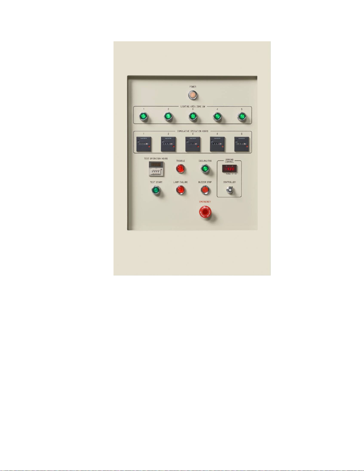
Check the chamber temperature reading at the control panel to ensure
an overheat condition does not exist. If the temperature reading is
below 100 ºC, troubleshoot the thermocouple controller. If the
temperature reading is above 100 ºC, ensure the cooling fans are
operating correctly. If fans are operating properly, please contact EYE
Lighting technical support.
Lamp Failure
Detection
Continues for 10
minutes after
occurrence of
failure
X Lamp failure to start, or failure during
operation. Starter failure at startup.
From a cold start, a solar lamp should start within approximately 40
seconds. If a lamp does not start within this timeframe, the LAMP
FAILURE indicator lamp will be illuminated and the system will shut
down. Replace the affected lamp and try to re-start system. If lamp still
doesn't start, troubleshoot the lamp starter (Power/Control cabinet)
and wiring from starter to lamp socket. If no problems are identified,
please contact EYE Lighting technical support.
Abnormal
Voltage
Limit
Continues for 10
minutes after
occurrence of
failure
X Solar lamp output power (DIMMING
CONTROL) set beyond maximum limit.
Irradiation intensity modulated voltage control (DIMMING CONTROL)
must be set between 0V - 10V. Re-set irradiation intensity and re-start
system. If failure persists, please contact EYE Lighting technical
support.
NOTE:
X = System component will cease operation immediately on failure
Table of contents
Popular Touch Terminal manuals by other brands

UNIONCOMMUNITY
UNIONCOMMUNITY AC-6000 Installation and wiring guide

HIK VISION
HIK VISION DS-K5032 Series user manual

HIK VISION
HIK VISION MinMoe DS-K1T671TM-3XF installation guide

Stec
Stec eigerPanel57C Hardware manual

Contec
Contec AI-1608AY-USB user guide

UNIONCOMMUNITY
UNIONCOMMUNITY UBio-X Face Premium installation guide