EZ Power Steering EZ ELECTRIC POWER STEERING User manual

EZ ELECTRIC POWER STEERING
INSTALLATION MANUAL
Austin Healy MKIII

2
CONTENTS
1. THE PRODUCT _______________________________________________ 3
2. OVERVIEW OF THE KIT ________________________________________ 4
3. INSTALLATION _______________________________________________ 5

3
Version C1
Date 1/2/19
This installation manual must be read very carefully to avoid mistakes.
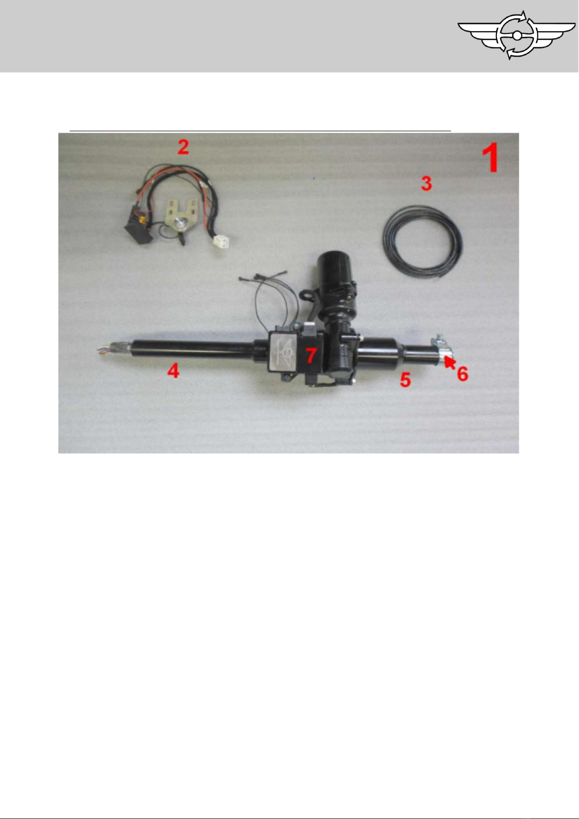
Check if all parts are present in the kit using the picture in the manual.
Compare the EZ Power Steering Column with the original column. Examine if the sizes are similar.
If you do not have the skills or tools to carry out the installation, then have a professional fit the kit
for you.
EZ Power Steering cannot be held accountable for a faulty installation or damages to the kit or
vehicle.
THE PRODUCT
Thank you for choosing an EZ ELECTRIC
POWER STEERING product for its
quality, it’s performance, type approval
and its straightforward assembly. Since
2006 we have been manufacturing
complete steering columns with
integrated electrical assistance. All columns
are tailor made for each type of car and
we have over 200 different types in stock.
For more information about our products
(power steering systems and replica
steering wheels) or to place an order, visit
our website www.ezpowersteering.com
or send an e-mail to
info@ezpowersteering.nl. If you have any
questions of a technical nature please
contact workshop@ezpowersteering.nl.

4
OVERVIEW OF THE KIT
EZ-AH3-1. Complete Set
EZ-AH3-2. Wiring loom with potientiometer
EZ-AH3-3. 6mm2 electric cable
EZ-AH3-4. Input side
EZ-AH3-5. Output side
EZ-AH3-6. Clamp
EZ-AH3-7. ECU
2
3
5
6
1
4

5
INSTALLATION
Step 1.
Check tire pressure, take the car for a test drive and check the steering system
for defects and alignment. If everything is working correctly, continue with the
conversion.
Step 2.
Locate an ignition switched plus wire and label it. Disconnect the earth cable from
battery (also check if the car has a positive or negative earth). Align the front
wheels straight ahead and mark their position.
Step 3.
Remove the indicator light switch and
cut the wiring.

6
Step 4.
Remove both dash gauges to improve
accessibility.
Step 5.
Measure the distance from the steering
shaft to the dash. Make a note of this.

7
Step 6.
Remove the upper mounting bracket
from the original steering column
Step 7.
Remove the cover to get access to the
lower mounting points from the steering
column.

8
Step 8.
Remove the lower mounting bolts from
the original column (via the removed
cover). The bracket needs to be cut, so
that it can be removed completely. (see
photo for cutting line).
Step 9.
Cut the steering tube as low as possible.

9
Step 10.
Cut the steering shaft at the right length.
Measure the length from the power
steering columns, including the output
shaft. This length can be cut off from the
original shaft. (Caution: do not measure
the length from the piece which goes
into the steering shaft).
Step 11.
Loosen the nut from the steering box
which guides the wires internal. Push it
about 10cm through and cut this length
off (this is needed to fit the output shaft
inside the original steering shaft.

10
Step 12.
Fit the output shaft in the original
steering shaft. Weld it to the original
shaft.
CAUTION: the EZ output shaft is ready
to fit the original steering shaft. Once the
original steering shaft has been replaced,
it's possible that the EZ output shaft
doesn't fit. The standard internal
diameter for a replacement steering shaft
is normally 13.95mm. Check this and
adapt the EZ output shaft if needed.
Step 13.
Cut about 1cm out of the area at the
steering tube. It's marked red on the
photo. This is needed to give the clamp
enough clearance while mounting.

11
Step 14.
Slide the mounting clamp over the
steering tube.
Step 15.
Install the mounting bracket behind the
gauges.

12
Step 16.
Connect the EZ power steering harness
to the car. Check if the car is positive or
negative earth.
Step 17a.
NEGATIVE EARTH: Connect the thick red wire (30+) through the fuse holder
direct to the battery plus.
Fahrgestell.
Step 18a.
Connect the thin red wire (15+) to an ignition switched plus (12v). See point 2.
Step 17b.
POSITIVE EARTH: Connect the thick red wire (30+) to a suitable point at the
chassis.
Step 19a.
Connect the black wire (31-) to a suitable earth point.

13
Step 18b.
Connect the thin red wire at the same point as the 30+ wire. Connect the
white wire to the ignition switched earth. (see attachments at last page).
Step 19b.
Connect the black wire, through the fuse holder directly with the battery
negative
Step 20.
Find a suitable location for the potentiometer and install it.

14
Step 21.
Slide the output flange over the original
tube. Slide the clamp over the output
shaft afterwards.
Step 22.
Install the EZ unit onto the output flange.
Tighten all 3 mounting bolts. The clamp
from the output shaft can be fastened
through the opening into the output
flange.

15
Step 23.
Position the EZ unit into the right,
position (also see point 5) and tighten
the lower clamp through the heater
channel (see point 14).
Step 24.
Install the upper clamp and tighten it.

16
Step 25.
Cut off the tube from the indicator
switch (be careful not to damage the
internal wiring). For the best result it is
best to use a pipe cutter.
Step 26.
Weld the inner ring to the outer ring.
Use 3 spot-welds to do this. Crimp the
connectors to the wiring so that it can
be connected to the EZ unit wiring.

17
Step 27.
Use a multimeter to determine which
wires correspond (wires through the
steering shaft and contact pins) Install
steering wheel and indicator switch to
the EZ unit. Connect the original wiring
from the indicator switch to the contact
pins at the EZ unit.
Step 28.
Install both dash gauges together with
cover underneath heater channel (see
point 7).
Step 29.
Reconnect battery earth , after switching on the ignition a click from the ECU
should be noticeable. The system is now operational, check this! Also check the
function from the indicator horn switch. After the ignition has been switched off
it takes approx. 3 sec. before the EZ unit switches off, again noticeable by a
click. Check this.

18
Step 30.
Take a test drive and recheck that all systems are functioning correctly.
Step 31.
The end result.
(Picture is an example of an Austin
Healey with a collapsible column.)

19
Positive Earth Attachment.
When you have a positive earth car, the EZ Powersteering wire harness has a extra relay
which switches the 15+. See the schematic below.
Keep in mind, that at a positive earth car, the battery + is connected to the chassis. The
Thick red wire (30+) needs to be connected to the chassis. In some case it's necessary to
isolate the ECU housing from the chassis! (to be sure, measure from earth wire to housing).
The thin red wire (15+) is connected with the relay (pin 87).
The black wire is connected via the fuse holder directly to battery -.
The White wire is connected to an ignition switched earth (simplest option is to use the
switched earth wire from the ignition coil).

20
Popular Automobile Accessories manuals by other brands

Directechs
Directechs DB3 installation guide

Prorack
Prorack K402 Fitting instructions

Metra Electronics
Metra Electronics 99-7415 installation instructions

Blaupunkt
Blaupunkt BT DRIVE FREE 112 OPERATING AND INSTALLATION Manual

Safe Fleet
Safe Fleet RVS systems RVS-M633 instruction manual

SecurView
SecurView MDVR-J400 quick start guide

Firmtec
Firmtec ELB 1985 manual

Thule
Thule 145012 quick start guide

Havis-Shields
Havis-Shields 1996-2006 Ford Taurus C-TCB-10 Install instructions

Sinister Diesel
Sinister Diesel 2004.5-2005 LLY EGR Delete Kit installation instructions

Paulchen System
Paulchen System Economy Class Mounting instructions

TruXedo
TruXedo TonneauTraX owner's manual