Ezgo ST 400 48V User manual

OWNER'S MANUAL
&
SERVICE GUIDE
ELECTRIC POWERED VEHICLE
612307
ISSUED MAY 2009
400 48V

(NOTES, CAUTIONS AND WARNINGS CONTINUED ON INSIDE OF BACK COVER)
SAFETY
For any questions on material contained in this manual, contact an authorized representative for clarification.
Read and understand all labels located on the vehicle. Always replace any damaged or missing labels.
On steep hills it is possible for vehicles to coast at greater than normal speeds encountered on a flat surface. To pre-
vent loss of vehicle control and possible serious injury, speeds should be limited to no more than the maximum speed
on level ground. See GENERAL SPECIFICATIONS. Limit speed by applying the service brake.
Catastrophic damage to the drivetrain components due to excessive speed may result from driving the vehicle above
specified speed. Damage caused by excessive speed may cause a loss of vehicle control, is costly, is considered
abuse and will not be covered under warranty.
For towing/transporting vehicle, refer to “TRANSPORTING VEHICLE”.
Vehicles equipped with Precision Drive System™ (PDS) must be towed with the Run-Tow/Maintenance switch, located
under the passenger seat, in the ‘Tow/Maintenance’ position.
Signs similar to the ones illustrated should be used to warn of situations that could result in an unsafe condition.
Be sure that this manual remains as part of the permanent service record should the vehicle be sold.
WASH HANDS
AFTER HANDLING!
Battery posts,
terminals and related
accessories contain
lead and lead compounds,
chemicals known
to cause cancer and
reproductive harm.
BATTERY WARNING
WASH HANDS
AFTER HANDLING!
WARNING: Battery posts, terminals and related
accessories contain lead and lead compounds,
chemicals known to cause cancer and reproductive harm.
BATTERIES
CONTAIN LEAD
AND RELATED PARTS
!
<
14
˚
25
%
DO NOT
DRIVE ACROSS
SLOPES IN
EXCESS OF 14˚
Throughout this guide NOTE, CAUTION and WARNING
will be used.
A NOTE indicates a condition that should be observed.
A CAUTION indicates a condition that may result in
damage to the vehicle.
A WARNING indicates a hazardous condition
that could result in severe injury or death.
Observe these NOTES, CAUTIONS and WARNINGS;
be aware that servicing a vehicle requires mechanical
skill and a regard for conditions that could be hazardous.
Improper service or repair may damage the vehicle or
render it unsafe.
Battery posts, terminals and related accesso-
ries contain lead and lead compounds. Wash
hands after handling.

Page i
Owner’s Manual and Service Guide
OWNER’S MANUAL
AND SERVICE GUIDE
ELECTRIC POWERED
UTILITY VEHICLES
ST 400 E
Starting Model Year 2009
The E-Z-GO Division of Textron Inc. reserves the right to incorporate engineering and design changes to products in this Manual, without obligation to include
these changes on units leased/sold previously.
The information contained in this Manual may be revised periodically by the E-Z-GO Division, and therefore is subject to change without notice.
The E-Z-GO Division DISCLAIMS LIABLITY FOR ERRORS IN THIS MANUAL, and the E-Z-GO Division SPECIFICALLY DISCLAIMS LIABILITY FOR INCIDEN-
TAL AND CONSEQUENTIAL DAMAGES resulting from the use of the information and materials in this Manual.
TO CONTACT US
NORTH AMERICA:
TECHNICAL ASSISTANCE & WARRANTY PHONE: 1-800-774-3946, FAX: 1-800-448-8124
SERVICE PARTS PHONE: 1-888-GET-EZGO (1-888-438-3946), FAX: 1-800-752-6175
INTERNATIONAL:
PHONE: 001-706-798-4311, FAX: 001-706-771-4609
E-Z-GO DIVISION OF TEXTRON, INC., 1451 MARVIN GRIFFIN ROAD, AUGUSTA, GEORGIA USA 30906-3852

Page ii Owner’s Manual and Service Guide
GENERAL INFORMATION
This vehicle has been designed and manufactured in the United States of America (USA) as
a ‘World Vehicle’. The Standards and Specifications listed in the following text originate in
the USA unless otherwise indicated.
The use of non Original Equipment Manufacturer (OEM) approved parts may void the
warranty.
Overfilling battery may void the warranty.
BATTERY PROLONGED STORAGE
All batteries will self discharge over time. The rate of self discharge varies depending on the
ambient temperature and the age and condition of the batteries.
A fully charged battery will not freeze in winter temperatures unless the temperature falls
below -75° F (-60° C).
For winter storage, the batteries must be clean, fully charged and disconnected from any
source of electrical drain. The battery charger and the controller are both sources of
electrical drain. Unplug the battery charger DC plug from the vehicle receptacle.
As with all electric vehicles, the batteries must be checked and recharged as required or at a
minimum of 30 day intervals.

Page iii
TABLE OF CONTENTS
Owner’s Manual and Service Guide
SAFETY ................................................................................................................ Inside covers
GENERAL INFORMATION .......................................................................................................ii
SAFETY INFORMATION ........................................................................................................... v
GENERAL ................................................................................................................................. ix
BEFORE INITIAL USE ..............................................................................................................1
Fig. 1 Initial Service Chart .........................................................................................................1
PORTABLE CHARGER INSTALLATION ............................................................................................................1
Fig. 2 Proper Charger Installation .............................................................................................2
Fig. 3 Charger Receptacle Location .........................................................................................2
CONTROLS AND INDICATORS ............................................................................................... 2
KEY/LIGHT SWITCH ...........................................................................................................................................2
Fig. 4 Key/Light Switch & State of Charge Meter .....................................................................3
DIRECTION SELECTOR .....................................................................................................................................3
Fig. 5 Direction Selector Types .................................................................................................3
STATE OF CHARGE METER .............................................................................................................................3
HOUR METER ..................................................................................................................................................... 3
ACCELERATOR PEDAL .....................................................................................................................................3
Fig. 6 Accelerator and Brake Controls ......................................................................................3
COMBINATION SERVICE BRAKE AND PARK BRAKE PEDAL ........................................................................4
RUN - TOW/MAINTENANCE SWITCH (PDS VEHICLES ONLY) .............................................4
Fig. 7 Run-Tow/Maintenance Switch ........................................................................................4
PLASTIC LOADBED .................................................................................................................4
MANUAL LIFT BED OPERATION .......................................................................................................................5
Fig. 8 Manual Bed Latch ...........................................................................................................5
TAILGATE OPERATION .....................................................................................................................................5
OPERATING THE VEHICLE ..................................................................................................... 5
PRECISION DRIVE SYSTEM™ ..........................................................................................................................6
Regenerative Braking .............................................................................................................................6
Pedal-Up Braking ....................................................................................................................................6
Walk-Away Feature ................................................................................................................................7
Anti-Roll Back Feature ............................................................................................................................7
Anti-Stall Feature ....................................................................................................................................7
High Pedal Disable Feature ....................................................................................................................7
Default Mode Feature .............................................................................................................................7
STARTING AND DRIVING ..................................................................................................................................7
STARTING VEHICLE ON A HILL ........................................................................................................................8
COASTING ..........................................................................................................................................................8
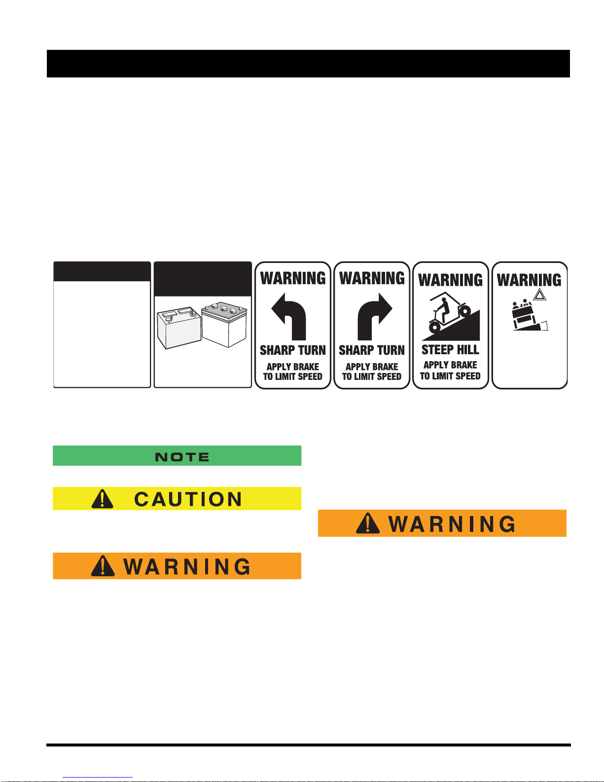
LABELS AND PICTOGRAMS .............................................................................................................................8
SUN TOP AND WINDSHIELD .............................................................................................................................8
TOWING A TRAILER ..........................................................................................................................................8
VEHICLE CLEANING AND CARE ............................................................................................9
VEHICLE CLEANING ..........................................................................................................................................9
REPAIR ......................................................................................................................................9
LIFTING THE VEHICLE ......................................................................................................................................9
Fig. 9 Lifting the Vehicle .........................................................................................................10
WHEELS AND TIRES ......................................................................................................................................10
Tire Repair ............................................................................................................................................10
Wheel Installation .................................................................................................................................11
Fig. 10 Wheel Installation .......................................................................................................11
LIGHT BULB REPLACEMENT ..........................................................................................................................11
Fig. 11 Headlight and Turn Signal Bulb Replacement ............................................................11
Fig. 12 Tail and Brake Light Bulb Replacement .....................................................................11
FUSE REPLACEMENT .....................................................................................................................................11
TRANSPORTING VEHICLE ....................................................................................................12
TOWING ............................................................................................................................................................12

Page iv Owner’s Manual and Service Guide
TABLE OF CONTENTS
HAULING .......................................................................................................................................................... 12
SERVICE AND MAINTENANCE ..............................................................................................12
SERIAL NUMBER PLATE AND LOCATION .................................................................................................... 13
Fig. 13 Serial Number Plate and Location ............................................................................. 13
PERIODIC SERVICE SCHEDULE .................................................................................................................. 14
Fig. 14 Periodic Service Schedule ......................................................................................... 14
TIRE INSPECTION ........................................................................................................................................... 15
BRAKES ........................................................................................................................................................... 15
Periodic Brake Test for Mechanical Brakes ......................................................................................... 15
Fig. 15 Typical Brake Performance Test ................................................................................ 16
REAR AXLE ...................................................................................................................................................... 16
Checking the Lubricant Level ............................................................................................................... 16
LUBRICATION .................................................................................................................................................. 16
Fig. 16 Add, Check and Drain Axle Lubricant ........................................................................ 17
Fig. 17 Lubrication Points ....................................................................................................... 17
PDS SYSTEM TEST ......................................................................................................................................... 17
HARDWARE ..................................................................................................................................................... 17
CAPACITIES AND REPLACEMENT PARTS ................................................................................................... 17
Fig. 18 Capacities and Replacement Parts ............................................................................ 17
BATTERIES AND CHARGING ................................................................................................17
SAFETY ............................................................................................................................................................ 17
Fig. 19 Torque Specifications and Bolt Grades ....................................................................... 18
BATTERY ......................................................................................................................................................... 18
BATTERY MAINTENANCE .............................................................................................................................. 19
At Each Charging Cycle ....................................................................................................................... 19
Monthly ................................................................................................................................................. 19
Electrolyte Level and Water ................................................................................................................. 19
Fig. 20 Correct Electrolyte Level ............................................................................................ 19
Fig. 21 Water Purity Table ..................................................................................................... 20
Fig. 22 Automatic Watering Gun ............................................................................................ 20
Battery Cleaning ................................................................................................................................... 20
Battery Replacement ............................................................................................................................ 21
Fig. 23 Preparing Acid Neutralizing Solution .......................................................................... 21
Fig. 24 36V Battery Connections ........................................................................................... 21
Prolonged Storage ............................................................................................................................... 21
BATTERY CHARGING ..................................................................................................................................... 22
Fig. 25 Freezing Point of Electrolyte ...................................................................................... 22
AC Voltage ........................................................................................................................................... 23
TROUBLESHOOTING ...................................................................................................................................... 23
Hydrometer .......................................................................................................................................... 23
Fig. 26 Hydrometer ................................................................................................................ 24
Using A Hydrometer ............................................................................................................................. 24
Fig. 27 Hydrometer Temperature Correction ......................................................................... 24
GENERAL SPECIFICATIONS .................................................................................................27
ST 400 E ........................................................................................................................................................... 28
Fig. 28 Vehicle Dimensions ....................................................................................................29
Fig. 29 Vehicle Dimensions, Incline Specifications and Turning Clearance Diameter ........... 30
LIMITED WARRANTIES ..........................................................................................................31
(U.S. AND CANADA) ........................................................................................................................................ 32
LABELS AND PICTOGRAMS ............................................................................Appendix A - 1
DECLARATION OF CONFORMITY (EUROPE ONLY) ......................................Appendix B - 1

Owner’s Manual and Service Guide Page v
SAFETY INFORMATION
This manual has been designed to assist in maintaining the vehicle in accordance with procedures developed by the
manufacturer. Adherence to these procedures and troubleshooting tips will ensure the best possible service from the
product. To reduce the chance of personal injury or property damage, the following must be carefully observed:
Certain replacement parts can be used independently and/or in combination with other accessories to modify an E-Z-
GO-manufactured vehicle to permit the vehicle to operate at or in excess of 20mph. When an E-Z-GO-manufactured
vehicle is modified in any way by the Distributor, Dealer or customer to operate at or in excess of 20mph, UNDER FED-
ERAL LAW the modified product will be a Low Speed Vehicle (LSV) subject to the strictures and requirements of Fed-
eral Motor Vehicle Safety Standard 571.500. In these instances, pursuant to Federal law the Distributor or Dealer
MUST equip the product with headlights, rear lights, turn signals, seat belts, top, horn and all other modifications for
LSV’s mandated in FMVSS 571.500, and affix a Vehicle Identification Number to the product in accordance with the
requirements of FMVSS 571.565. Pursuant to FMVSS 571.500, and in accordance with the State laws applicable in the
places of sale and use of the product, the Distributor, Dealer or customer modifying the vehicle also will be the Final
Vehicle Manufacturer for the LSV, and required to title or register the vehicle as mandated by State law.
E-Z-GO will NOT approve Distributor, Dealer or customer modifications converting E-Z-GO products into LSV’s.
The Company, in addition, recommends that all E-Z-GO products sold as personal transportation vehicles BE OPER-
ATED ONLY BY PERSONS WITH VALID DRIVERS LICENSES, AND IN ACCORDANCE WITH APPLICABLE STATE
REQUIREMENTS. This restriction is important to the SAFE USE AND OPERATION of the product. On behalf of E-Z-
GO, I am directing that E-Z-GO Branch personnel, Distributors and Dealers advise all customers to adhere to this
SAFETY RESTRICTION, in connection with the use of all products, new and used, the Distributor or Dealer has rea-
son to believe may be operated in personal transportation applications.
Information on FMVSS 571.500 can be obtained at Title 49 of the Code of Federal Regulations, section 571.500, or
through the Internet at the website for the U.S. Department of Transportation - at Dockets and Regulation, then to Title
49 of the Code of Federal Regulations (Transportation).
GENERAL
Many vehicles are used for a variety of tasks beyond the original intended use of the vehicle; therefore, it is impossible
to anticipate and warn against every possible combination of circumstances that may occur. No warnings can take the
place of good common sense and prudent driving practices.
Good common sense and prudent driving practices do more to prevent accidents and injury than all of the warnings
and instructions combined. The manufacturer strongly suggests that all users and maintenance personnel read this
entire manual paying particular attention to the CAUTIONS and WARNINGS contained therein.
If you have any questions regarding this vehicle, contact your closest representative or write to the address on the back
cover of this publication, Attention: Product Service Department.
The manufacturer reserves the right to make design changes without obligation to make these changes on units previ-
ously sold and the information contained in this manual is subject to change without notice.
The manufacturer is not liable for errors in this manual or for incidental or consequential damages that result from the
use of the material in this manual.
This vehicle conforms to the current applicable standard(s) for safety and performance requirements.

Page vi
SAFETY INFORMATION
These vehicles are designed and manufactured for off-road use. They do not conform to Federal Motor Vehicle Safety
Standards of the United States of America (USA) and are not equipped for operation on public streets. Some commu-
nities may permit these vehicles to be operated on their streets on a limited basis and in accordance with local ordi-
nances.
Refer to GENERAL SPECIFICATIONS for vehicle seating capacity.
With electric powered vehicles, be sure that all electrical accessories are grounded directly to the battery (-) post.
Never use the chassis or body as a ground connection.
Never modify the vehicle in any way that will alter the weight distribution of the vehicle, decrease its stability
or increase the speed beyond the factory specification. Such modifications can cause serious personal injury
or death. Modifications that increase the speed and/or weight of the vehicle will extend the stopping distance and may
reduce the stability of the vehicle. Do not make any such modifications or changes. The manufacturer prohibits and
disclaims responsibility for any such modifications or any other alteration which would adversely affect the safety of the
vehicle.
Vehicles that are capable of higher speeds must limit their speed to no more than the speed of other vehicles when
used in a golf course environment. Additionally, speed should be further moderated by the environmental conditions,
terrain and common sense.
GENERAL OPERATION
Always:
• Use the vehicle in a responsible manner and maintain the vehicle in safe operating condition.
• Read and observe all warnings and operation instruction labels affixed to the vehicle.
• Follow all safety rules established in the area where the vehicle is being operated.
• Reduce speed to compensate for poor terrain or conditions.
• Apply service brake to control speed on steep grades.
• Maintain adequate distance between vehicles.
• Reduce speed in wet areas.
• Use extreme caution when approaching sharp or blind turns.
• Use extreme caution when driving over loose terrain.
• Use extreme caution in areas where pedestrians are present.
MAINTENANCE
Always:
• Maintain the vehicle in accordance with the manufacturer’s periodic service schedule.
• Ensure that repairs are performed by those that are trained and qualified to do so.
• Follow the manufacturer’s maintenance procedures for the vehicle. Be sure to disable the vehicle before performing
any maintenance. Disabling includes removing the key from the key switch and removal of a battery wire.

Page vii
SAFETY INFORMATION
• Insulate any tools used within the battery area in order to prevent sparks or battery explosion caused by shorting the
battery terminals or associated wiring. Remove the battery or cover exposed terminals with an insulating material.
• Check the polarity of each battery terminal and be sure to rewire the batteries correctly.
• Use specified replacement parts. Never use replacement parts of lesser quality.
• Use recommended tools.
• Determine that tools and procedures not specifically recommended by the manufacturer will not compromise the
safety of personnel nor jeopardize the safe operation of the vehicle.
• Support the vehicle using wheel chocks and jack stands. Never get under a vehicle that is supported by a jack. Lift
the vehicle in accordance with the manufacturer’s instructions.
• Maintain the vehicle in an area away from exposed flame or persons who are smoking.
• Be aware that a vehicle that is not performing as designed is a potential hazard and must not be operated.
• Test drive the vehicle after any repairs or maintenance. All tests must be conducted in a safe area that is free of both
vehicular and pedestrian traffic.
• Replace damaged or missing warning, caution or information labels.
• Keep complete records of the maintenance history of the vehicle.
The manufacturer cannot anticipate all situations, therefore people attempting to maintain or repair the vehicle must
have the skill and experience to recognize and protect themselves from potential situations that could result in severe
personal injury or death and damage to the vehicle. Use extreme caution and, if unsure as to the potential for injury,
refer the repair or maintenance to a qualified mechanic.
VENTILATION
Hydrogen gas is generated in the charging cycle of batteries and is explosive in concentrations as low as 4%. Because
hydrogen gas is lighter than air, it will collect in the ceiling of buildings necessitating proper ventilation. Five air
exchanges per hour is considered the minimum requirement.
Never charge a vehicle in an area that is subject to flame or spark. Pay particular attention to natural gas or propane
gas water heaters and furnaces.
Always use a dedicated circuit for each battery charger. Do not permit other appliances to be plugged into the recepta-
cle when the charger is in operation.
Chargers must be installed and operated in accordance with charger manufacturers recommendations or applicable
electrical code (whichever is higher).

Owner’s Manual and Service Guide Page ix
SAFETY INFORMATION
GENERAL
The following text is provided as recommended by part II of ANSI/ITSDF B56.8 - 2006. The manufacturer strongly
endorses the contents of this specification.
6 GENERAL SAFETY PRACTICES
6.1 Introduction
6.1.1 Like other machines, carriers can cause injury if improperly used or maintained. Part II contains broad safety
practices applicable to carrier operation. Before operation, the user shall establish such additional specific safety prac-
tices as may reasonably be required for safe operation.
6.1.2 Premise review — The user shall periodically review their premises, and as conditions warrant, identify areas
where carriers should not be operated and to identify possible hazards such as the following examples:
a) Steep Grade — In areas where steep grades exist, carrier operation should be restricted to the designated vehi-
cle’s pathways where possible, and shall be identified with a suitable warning giving the following information:
“Warning, steep grade.”
b) Wet Areas — Wet areas could cause a carrier to lose traction and could affect steering, stability and braking.
c) Sharp Turns, Blind Spots, Bridge Approaches — Sharp turns, blind spots, bridge approaches, and other poten-
tially hazardous areas shall be identified with a suitable warning to the operator of the nature of the hazard and
stating the proper precautions to be taken to avoid the hazard.
d) Loose Terrain — Loose terrain could cause a carrier to lose traction and could affect steering, stability, and
braking.
6.2 Operation
Experience has shown that carriers, which comply with the provisions, stated in paragraph 9.3.9 are stable when
properly operated and when operated in accordance with specific safety rules and practices established to meet actual
operating terrain and conditions. However, improper operation, faulty maintenance, or poor housekeeping may contrib-
ute to a condition of instability and defeat the purpose of the standard. Some of the conditions which may affect stability
are failure of the user to follow safety practices; also, ground and floor conditions, grade, speed, loading, the operation
of the carrier with improper loads, battery weight, dynamic and static forces, and the judgment exercised by the carrier
operator.
a) The user shall train carrier operators to adhere strictly to the operating instructions stated in this Standard.
b) The user shall survey specific operating conditions and environment, and establish and train carrier operators to
comply with additional, specific safety practices.
6.3 Nameplates, Markings, Capacity, and Modifications
6.3.1 The user shall maintain in a legible condition all nameplates, warnings, and instructions, which are supplied by
the manufacturer.
6.3.2 Except as provided in 6.3.4, no modifications or alterations to a carrier, which may affect the capacity, stability,
or safe operation of the carrier, shall be made without the prior written approval of the original carrier manufacturer or a
successor thereof. When the carrier manufacturer or its successor approves a modification or alteration, appropriate
changes shall be made to capacity plates, decals, tags, and operation and maintenance manuals
6.3.3 As required under paragraphs 6.3.1 or 6.3.2, the manufacturer shall be contacted to secure new nameplates,
warnings, or instructions, which shall then be affixed in their proper place on the carrier.
6.3.4 In the event that the carrier manufacturer is no longer in business and there is no successor in interest to the
business, the user may arrange for a modification or alteration to a carrier, provided however, the controlling party
shall:

Page x
SAFETY INFORMATION
(1) Arrange for the modification or alteration to be designed, tested, and implemented by an engineer(s) expert in
carrier(s) and their safety;
(2) Maintain a permanent record of the design, test(s), and implementation of the modification or alteration;
(3) Make appropriate changes to the capacity plate(s), decals, tags, and operation and maintenance manuals;
(4) Affix a permanent and readily visible label on the carrier stating the manner in which the carrier has been mod-
ified or altered together with the date of the modification or alteration, and the name of the organization that
accomplished the tasks.
6.4 Fuel Handling and Storage
6.4.1 The user shall supervise the storage and handling of liquid fuels (when used) to be certain that it is in accor-
dance with ANSI/NFPA 505 and ANSI/NFPA 30 or as required by local ordinance.
6.4.2 Storage and handing of liquefied petroleum gas fuels shall be in accordance with ANSI/NFPA 505 and ANSI/
NFPA 58 or as required by local ordinance. If such storage or handling is not in compliance with these standards, the
user shall prevent the carrier from being used until such storage and handling is in compliance with these standards.
6.4.3 Prevent fire and explosion caused by static electric discharge. Use only non-metal, portable fuel containers
approved by the Underwriter’s Laboratory (U.L.) or the American Society for Testing & Materials (ASTM). If using a fun-
nel, make sure it is plastic and has no screen or filter.
Static electric discharge can ignite gasoline vapors in an ungrounded fuel container. Remove the fuel container from
the bed of a carrier or the trunk of a car ban place on the ground away from the carrier before filling. Keep nozzle in
contact with container opening while filling. When practical, remove equipment from trailers or truck beds and re -fuel
them on the ground. If this is not possible, use a portable, plastic fuel container to refuel equipment on a truck bed or
trailer.
6.5 Changing and Charging Storage Batteries for Electric Personnel and Burden Carriers
6.5.1 The user shall require battery changing and charging facilities and procedures to be in accordance with ANSI/
NFPA 505 or as required by local ordinance.
6.5.2 The user shall periodically inspect facilities and review procedures to be certain that ANSI/NFPA 505 or as
required by local ordinance, are strictly complied with, and shall familiarize carrier operators with it.
6.5.3 Maintenance and storage areas for carriers shall be properly ventilated to avoid fire hazards in accordance
with applicable fire codes and ordinances.
Ventilation for internal combustion engine powered carriers shall be provided to remove flammable vapors (gases),
fumes and other flammable materials. Consult applicable fire codes for specific levels of ventilation.
Ventilation for electric powered carriers shall be provided to remove the accumulation of flammable hydrogen gas
emitted during the battery charging process. The amount of hydrogen gas emitted depends upon a number of factors
such as the condition of the batteries, the output rate of the battery charger and the amount of time the batteries are on
charge. Because of the highly volatile nature of hydrogen gas and its propensity to accumulate in pockets, a minimum
number of air changes per hour is required during charging.
Consult applicable fire and safety codes for the specific ventilation levels required as well as the use of explosion
proof electrical apparatus. SAE J1718 can be followed to check for hydrogen gas levels.
6.6 Hazardous Locations
6.6.1 The user shall determine the hazard classification of the particular atmosphere or location in which the carrier
is to be use in the accordance with ANSI/NFPA 505.
6.6.2 The user shall permit in hazardous areas only those carriers approved and of the type required by ANSI/NFPA
505.

Page xi
SAFETY INFORMATION
6.7 Lighting for Operating Area
The user, in accordance with his responsibility to survey the environment and operating conditions, shall determine if
the carrier requires lights and, if so, shall equip the carrier with appropriate lights.
6.8 Control of Noxious Gases and Fumes
When equipment powered by internal combustion engines is used in enclosed areas, the atmosphere shall be main-
tained within limits specified in the American Conference of Governmental Industrial Hygienists publication,:Threshold
Limit Values for Chemical Substances and Physical Agents in the Workroom Environment.” This may be accomplished
by ventilation maintenance of emission control equipment recommended or provided by the manufacturer of the equip-
ment.
6.9 Warning Device(s)
6.9.1 The user shall make periodic inspections of the carrier to be certain that the sound-producing and/or visual
device(s) if so equipped are maintained in good operating condition.
6.9.2 The user shall determine if operating conditions require the carrier to be equipped with additional sound-pro-
ducing or visual devices or both and be responsible for providing and maintaining such devices, in accordance with the
manufacturer’s recommendations.
6.10 Safety Interlocks
The user shall make periodic inspections of the carrier to be certain that the safety interlock system, if so equipped,
is operating properly.
7 OPERATING SAFETY RULES AND PRACTICES
7.1 Personnel and Burden Carrier Operator Qualifications
Only persons whoa are trained in the proper operation of the carrier shall be authorized to operate the carrier. Oper-
ators shall be qualified as to visual, auditory, physical, and mental ability to safely operate the equipment according to
Section 7, all other applicable parts of this Standard and the operators’ manual.
7.2 Personnel and Burden Carrier Operators’ Training
7.2.1 The user shall conduct an operators’ training program.
7.2.2 Successful completion of the operators’ training program by the operator shall be required before operation of
the carrier. The program shall be presented in its entirely to all-new operators and not condensed for those claiming
previous experience.
7.2.3 The user shall include as a minimum in the operators’ training program the following.
a) Instructional material provided by the manufacturer including the operators; manual;
b) Emphasis on safety of passengers, material loads, carrier operator, and other person(s);
c) General safety rules contained within this Standard and the additional specific rules determined by the user in
accordance with this Standard, and why they were formulated;
d) Introduction of equipment, control locations of the environment which could affect carrier operation;
e) Operator competency evaluations.
7.3 Personnel and Burden Carrier Operator Responsibility
7.3.1 General Operator Responsibility

Page xii
SAFETY INFORMATION
7.3.1.1 Read and follow operators’ manual
7.3.1.2 Do not operate carrier under the influence of drugs and alcohol.
7.3.1.3 Safeguard the pedestrians at all times. Do not drive carrier in a manner that would endanger other persons.
7.3.1.4 Riding on the carrier by persons other than the operator is authorized only on personnel seat(s) provided by
the manufacturer. All parts of each person’s body shall remain within the plan view outline of the carrier.
7.3.1.5 When a carrier is to be left unattended, stop the carrier, apply the parking brake, stop the engine or turn off
power, turn off the control or ignition circuit, and remove the key if provided. Additionally, for the electric carriers, the forward and
reverse directional controls, should be neutralized if a means is provided. Block the wheels if the carrier is on a n incline.
7.3.1.6 A carrier is considered unattended when the operator is 7.6m (25 ft.) or more from the carrier which remains
in his view, or whenever the operator leaves the carrier and it is not within his view. When the operator is dismounted and within
7.6m (25 ft.) of the carrier still in his view, he still must have controls neutralized, and the parking brake(s) set to prevent movement.
7.3.1.7 Maintain a safe distance from potential hazards, such as edges of ramps and platforms.
7.3.1.8 Use only approved carriers in hazardous locations, as defined in the appropriate safety standards.
7.3.1.9 Report all accidents to the user.
7.3.1.10 Do not add to, or modify, the carrier.
7.3.1.11 Carriers shall not be parked or left unattended such that they block or obstruct fire aisles, access to stair-
ways, or fire equipment.
7.3.1.12 Only operate carrier while within operator’s station.
7.3.2 Traveling
7.3.2.1 Observe all traffic regulations, including authorized speed limits. Under normal traffic conditions keep to the
right. Maintain a safe distance, based on speed of travel, from a carrier or vehicle ahead, and keep the carrier under control at all
times.
7.3.2.2 Yield the right of way to pedestrians, ambulances, fire trucks, or other carriers or vehicles in emergency sit-
uations.
7.3.2.3 Do not pass another carrier or vehicle traveling in the same direction at intersections, blind spots, or at other
dangerous locations.
7.3.2.4 Keep a clear view of the path of travel, observe other traffic and personnel, and maintain a safe clearance.
7.3.2.5 Slow down or stop, as conditions dictate, and activate the sound-producing warning device at cross aisles
and when visibility is obstructed at other locations.
7.3.2.6 Ascend or descend grades slowly.
7.3.2.7 Avoid turning, if possible, and use caution on grades, ramps, or inclines, normally travel straight up and
down.
7.3.2.8 Under all travel conditions the carrier shall be operated at a speed that will permit it to be brought to a stop
in a safe manner.
7.3.2.9 Make starts, stops, turns, or direction reversals in a smooth manner so as not to shift the load, endanger
passengers, or lose control of the carrier.
7.3.2.10 Do not operate carrier in a dangerous manner.
7.3.2.11 Slow down when approaching, or on, wet or slippery surfaces.
7.3.2.12 Do not drive carrier onto any elevator unless specifically authorized to do so. Approach elevators slowly,
and then enter squarely after the elevator car is properly leveled. Once on the elevator, neutralize the controls, shut off power, and
set parking brakes. It is advisable that all other personnel leave the elevator before a carrier is allowed to enter or exit.
7.3.2.13 Avoid running over loose objects, potholes, and bumps.
7.3.2.14 Reduce carrier speed to negotiate turns.
7.3.2.15 Avoid any action verbal or physical by an operator or passenger, which could cause the operator to be dis-
tracted.
7.3.3 Loading
7.3.3.1 Refer to operators’ manual for loading instruction.

Page xiii
SAFETY INFORMATION
7.3.3.2 Handle only stable and safely arranged loads. When handling off-center loads, which cannot be centered,
operate with extra caution.
7.3.3.3 Handle only loads within the capacity of each cargo area of the carrier as specified by the manufacturer.
7.3.3.4 Avoid material loads exceeding the physical dimensions of the carrier or as specified by the carrier manu-
facturer.
7.3.4 Operator Care of Personnel and Burden Carriers
7.3.4.1 Read and follow operators’ manual.
7.3.4.2 At the beginning of each shift during which the carrier will be used, the operator shall check the carrier con-
dition and inspect the tires, warning devices, lights, battery(s), speed and directional controllers, brakes, safety interlocks, and steer-
ing mechanism. If the carrier is found to be in need of repair, or in any way unsafe, the matter shall be reported immediately to the
user and the carrier shall not be operated until it has been restored to safe operating condition.
7.3.4.3 If during operation the carrier becomes unsafe in any way, the matter shall be reported immediately to the
user, and the carrier shall not be operated until it has been restored to safe operating condition.
7.3.4.4 Do not make repairs or adjustments unless specifically trained and authorized to do so.
7.3.4.5 Before refueling, the engine shall be stopped and allowed to cool. The operator and passengers shall leave
the carrier before refueling.
7.3.4.6 Spillage of hazardous materials shall be contained immediately and addressed via appropriate hazardous
materials regulations.
7.3.4.7 Do not operate a carrier with a leak in the fuel system or battery(s). Battery(s) shall be charged and serviced
per manufacturer’s instructions.
7.3.4.8 Do not use open flames for checking electrolyte level in storage battery(s) or liquid level in fuel tanks.
8 MAINTENANCE PRACTICES
8.1 Introduction
Carriers may become hazardous if maintenance is neglected. Maintenance facilities, trained personnel, and proce-
dures shall be provided. Such facilities may be on or off the premises.
8.2 Maintenance Procedures
Maintenance and inspection of all carriers shall be performed in conformance with the following practices and should
follow the manufacturer’s recommendations.
a) A scheduled preventive maintenance, lubrication, and inspection system shall be followed.
b) Only trained and authorized personnel shall be permitted to maintain, repair, adjust, and inspect carriers.
c) Before undertaking maintenance or repair follow the manufacturer’s recommendations for immobilizing the car-
rier.
d) Chock wheels and support carrier, before working underneath it.
e) Before disconnecting any part of the engine fuel system, be sure the shutoff valve, if so equipped, is closed and
follow carrier manufacturer’s recommended practice.
f) Operation to check performance of the carrier shall be conducted in an authorized area where suitable condi-
tions exist, free of vehicular and pedestrian traffic.
g) Before returning carrier to service, follow the manufacturer’s instructions and recommended procedure.
h) Avoid fire hazards and have fire protection equipment present in the work area. Do not use an open flame to
check level or leakage of fuel, battery electrolyte, or coolant.
i) Properly ventilate the work area in accordance with applicable regulations or local ordinance.
j) Handle fuel cylinders with care. Physical damage, such as dents, scrapes, or gouges, may dangerously weaken
the tank and make it unsafe for use.

Page xiv
SAFETY INFORMATION
k) Brakes, steering mechanisms, speed and directional control mechanisms, warning devices, lights, governors,
guards, and safety devices shall be inspected regularly and maintained in accordance with manufacturer’s rec-
ommendations.
l) Special carriers or devices designed and approved for hazardous area operation shall be inspected to ensure
that maintenance preserves the original approved safe operating features.
m) Fuel systems shall be checked for leaks and condition of parts. If a leak is found, action shall be taken to prevent
the use to the carrier until the cause of the leak has been repaired.
n) The carrier manufacturer’s capacity, operation, and maintenance instruction plated, tags, or decals shall be
maintained in legible condition.
o) Batteries, motors, speed and directional controllers, limit switches, protective devices, electrical conductors/
insulators, and connections shall be inspected and maintained per carrier manufacturer’s recommendation.
p) Carriers shall be kept in a clean condition to minimize hazards and facilitate detection of components needing
service.
q) Modifications and additions which affect capacity and safe carrier operation shall not be performed without man-
ufacturer’s prior written authorization; where authorized modifications have been made, the user shall ensure
that capacity, operation, warning, and maintenance instruction plates, tags, or safety labels are changed accord-
ingly.
r) Care shall be taken to ensure that all replacement parts are interchangeable with the original parts and of a
quality at least equal to that provided in the original equipment.
s) Disconnect batteries, negative connection(s) first. When reconnecting, connect positive connection first.
t) Hydraulic systems, if so equipped, shall be checked for leaks, for condition of parts. Keep body and hands away
from pin-holes or nozzles that eject fluids under high pressure. Use paper or cardboard, not hands, to check for
leaks.
ANSI/ITSDF B56.8 - 2006

OPERATION AND SERVICE INFORMATION
Page 1
Owner’s Manual and Service Guide
Read all of Manual to become thoroughly familiar with this vehicle. Pay particular attention to all Notes, Cautions and Warnings
Thank you for purchasing this vehicle. Before driving the
vehicle, we ask you to spend some time reading this
Owner’s Manual and Service Guide. This guide contains
the information that will assist you in maintaining this
highly reliable vehicle. Some illustrations may show
items that are optional for your vehicle. This guide covers
the operation of several vehicles; therefore, some picto-
rial views may not represent your vehicle. Physical differ-
ences in controls will be illustrated.
This vehicle has been designed and manufactured as a
‘World Vehicle’. Some countries have individual require-
ments to comply with their specifications; therefore,
some sections may not apply in your country.
Most of the service procedures in this guide can be
accomplished using common automotive hand tools.
Contact your service representative on servicing the
vehicle in accordance with the Periodic Service Sched-
ule.
Service Parts Manuals and Technician’s Repair and Ser-
vice Manuals are available from a local Distributor, an
authorized Branch or the Service Parts Department.
When ordering parts or requesting information for your
vehicle, provide vehicle model, serial number and manu-
facture date code.
BEFORE INITIAL USE
Read, understand and follow the safety label on the
instrument panel. Be sure you understand how to oper-
ate the vehicle, its equipment and how to use it safely.
Maintaining good performance depends to a large extent
on the operator.
Hydrogen gas is generated as a natural part of
the lead acid battery charging process. A 4%
concentration of hydrogen gas is explosive and
could cause severe injury or death. Charging
must take place in an area that is adequately
ventilated (minimum of 5 air exchanges per
hour).
To reduce the chance of battery explosion that
could result in severe injury or death, never
smoke around or charge batteries in an area
that has open flame or electrical equipment that
could cause an electrical arc.
Hydrogen gas is generated in the charging cycle of bat-
teries and is explosive in concentrations as low as 4%.
Because hydrogen gas is lighter than air, it will collect in
the ceiling of buildings necessitating proper ventilation.
Five air exchanges per hour is considered the minimum
requirement.
Never charge a vehicle in an area that is subject to flame
or spark. Pay particular attention to natural gas or pro-
pane water heaters and furnaces.
Before a new vehicle is put into operation, the items
shown in the INITIAL SERVICE CHART must be per-
formed (Ref Fig. 1 on page 1).
Vehicle batteries must be fully charged before initial use.
Check for correct tire inflation. See GENERAL SPECIFI-
CATIONS.
Determine and record braking distance required to stop
vehicle for future brake performance tests.
Remove the protective clear plastic, that protect the seat
bottom and back rest during shipping, before placing the
vehicle in service.
Fig. 1 Initial Service Chart
PORTABLE CHARGER INSTALLATION
To reduce the possibility of overheating that
may cause serious damage to the charger and
create the potential for fire, do not block or
obstruct the airways. Portable chargers must
be mounted on a platform above the ground or
in such a manner as to permit the maximum air
flow underneath and around the charger.
ITEM SERVICE OPERATION
Batteries Charge batteries
Seats Remove protective plastic covering
Brakes Check operation and adjust if necessary
Establish acceptable stopping distance (mechanica
l
brakes only)
Check hydraulic brake fluid level if equipped
Tires Check air pressure (see SPECIFICATIONS)
Portable Remove from vehicle and properly mount
Charger
R
ef Isc 5

OPERATION AND SERVICE INFORMATION
Page 2 Owner’s Manual and Service Guide
Read all of Manual to become thoroughly familiar with this vehicle. Pay particular attention to all Notes, Cautions and Warnings
Fig. 2 Proper Charger Installation
Portable chargers are shipped with the vehicle. Prior to
vehicle or charger operation, chargers must be removed
and mounted on a platform or wall above the ground to
permit maximum air flow around and underneath the
charger. If the charger is operated in an outdoor location,
rain and sun protection must be provided (Ref Fig. 2 on
page 2). A dedicated circuit is required for the charger.
Refer to the charger manual for appropriate circuit pro-
tection. The charger may remain plugged in to the AC
outlet. To charge the vehicle, refer to the instruction
labels on the charger. Insert the polarized DC plug com-
pletely into the vehicle receptacle (Ref Fig. 3 on page 2).
Fig. 3 Charger Receptacle Location
The charger will automatically start a few seconds after
plug insertion. The charger will automatically stop when
batteries are fully charged and the DC plug can be
removed to permit use of the vehicle.
Looping the DC cord through the steering wheel when charg-
ing, serves as a good reminder to store the cord out of the way
when finished with charging. The DC plug can be damaged by
driving over or catching the cord on the vehicle when driving
away.
To reduce the possibility of a physical hazard
that could result in an electrical shock or elec-
trocution, be sure that the charger plug is not
damaged and is inserted into a grounded
receptacle.
The power (AC) cord is equipped with a
grounded plug, do not attempt to pull out, cut or
bend the ground post.
The charging (DC) cord is equipped with a polarized con-
nector which fits into a matching receptacle on the vehi-
cle.
If vehicle is to be charged with a non E-Z-GO charger, refer to
the instructions supplied with the charger.
CONTROLS AND INDICATORS
Vehicle controls and indicators consist of:
•key/light switch
•direction selector
•state of charge meter
•hour meter
•accelerator pedal
•combination service and park brake pedal
•horn
KEY/LIGHT SWITCH
Located on the dash panel, this switch enables the basic
electrical system of the vehicle to be turned on and off by
turning the key. To prevent inadvertent operation of the
vehicle when left unattended, the key should be turned to
the ‘OFF’ position and removed (Ref Fig. 4 on page 3).
Provide Protection From Elements
Do Not Block Louvered Airways
NEMA 15 - 5R Grounded AC Receptacle
110 - 120 VAC. Dedicated 15 AMP Circuit
Locations outside the US and Canada: Reference
appropriate local electrical code and charger manu-
facturer recommendations for AC power requirements
Ref Pci 1
Ref Crl 1
Charger
Receptacle
F
ront of
Vehicle

OPERATION AND SERVICE INFORMATION
Page 3
Owner’s Manual and Service Guide
Read all of Manual to become thoroughly familiar with this vehicle. Pay particular attention to all Notes, Cautions and Warnings
Fig. 4 Key/Light Switch & State of Charge Meter
If the vehicle is equipped with lights, the key switch has a
position to operate them, indicated by the light icon.
If the vehicle is equipped with manufacturer installed custom
accessories, some accessories remain operational with the key
switch in the ‘OFF’ position.
DIRECTION SELECTOR
To prevent loss of control, do not move Preci-
sion Drive System (PDS) vehicle direction
selector while the vehicle is in motion. Moving
the selector will result in a sudden slowing of
the vehicle and the beeping of a warning
device.
To reduce the possibility of component damage, the
vehicle must be completely stopped before moving the
direction selector.
On PDS models, if the direction selector is shifted before
the vehicle comes to a complete stop, a warning beeper
will activate.
Located on the seat support panel, this switch permits
the selection of either ‘F’ (forward), ‘R’ (reverse) or neu-
tral (the position between forward and reverse). Vehicle
should be left in neutral with park brake applied/locked
when unattended (Ref Fig. 5 on page 3).
Fig. 5 Direction Selector Types
STATE OF CHARGE METER
Located in the dash, the state of charge meter indicates
the amount of usable power in the batteries (Ref Fig. 4
on page 3).
HOUR METER
The hour meter indicates total hours of operation.
ACCELERATOR PEDAL
Unintentional movement of the accelerator ped-
al will release the park brake and may cause
the vehicle to move which could result in
severe injury or death.
With the key switch ‘ON’, depressing the accelerator
pedal starts the motor. When the pedal is released, the
motor will stop (Ref Fig. 6 on page 3). To stop the vehicle
more quickly, depress the service brake.
Fig. 6 Accelerator and Brake Controls
If key switch is ‘ON’ and park brake is set, depressing the
accelerator inadvertently will release the park brake and
will cause the vehicle to move which could cause severe
injury or death.
OFF
ON
State of Charge Meter
Direction Selector (PDS only)
Key/Light Switch
Ref Kes 1
FWD
REV
FWD
REV
Fo r w ar d
Re v e r se
Neut r al, as sho wn
Re v e r se
Neut ral
ef Dsl1
Park
Brake
Accelerator
PARK
Service
Brake
R
ef Abc 1

OPERATION AND SERVICE INFORMATION
Page 4 Owner’s Manual and Service Guide
Read all of Manual to become thoroughly familiar with this vehicle. Pay particular attention to all Notes, Cautions and Warnings
Depressing the accelerator pedal will release the park
brake if it is engaged. This is a feature to assure the vehi-
cle is not driven with the park brake engaged. Depress-
ing the accelerator pedal is not the preferred method of
releasing the park brake.
Depressing the lower section of the brake pedal is the pre-
ferred method of releasing the park brake to assure the longest
service life of brake components.
COMBINATION SERVICE BRAKE AND PARK
BRAKE PEDAL
The brake pedal incorporates a park brake feature (Ref
Fig. 6 on page 3). To engage, push down on the upper
section of the pedal until it locks in place. The park brake
will release when the service brake pedal is depressed.
Use the lower section of the brake pedal to operate the
service brake system.
RUN - TOW/MAINTENANCE SWITCH
(PDS VEHICLES ONLY)
To reduce the possibility of severe injury or
death resulting from loss of vehicle control,
consider the grade of the terrain the vehicle is
on and set vehicle’s park brake accordingly
before switching the Run - Tow/Maintenance
switch to the ‘Tow/Maintenance’ position. When
in the ‘Tow/Maintenance’ position, the Anti-Roll
Back and Walk-Away safety features of the
PDS system no longer function.
Before attempting to tow vehicle, move the Run-Tow/
Maintenance switch to the ‘Tow/Maintenance’ position.
Failure to do so will damage the controller or motor.
Before disconnecting or connecting a battery, or any oth-
er wiring, move the Run-Tow/Maintenance switch to the
‘Tow/Maintenance’ position.
After connecting a battery, or any other wiring, wait a
minimum of 30 seconds before moving the Run-Tow/
Maintenance switch to the ‘Run’ position.
The PDS vehicle is equipped with a two position switch
located under the passenger side of the seat on the con-
troller environmental cover (Ref Fig. 7 on page 4).
Fig. 7 Run-Tow/Maintenance Switch
With the switch in ‘TOW/MAINTENANCE’ position:
•the controller is deactivated
•the electronic braking system is deactivated which
allows the vehicle to be towed or roll freely
•the warning beeper is deactivated
With the switch in ‘RUN’ position:
•the controller is activated
•the electronic braking system and warning beeper
features are activated
PDS vehicles operate only in the ‘RUN’ position.
The PDS is a low power consumption unit but it will drain
the vehicle batteries over a period of time. If the vehicle
is to be stored for a prolonged period of time, the PDS
should be disconnected from the batteries. (Refer to Pro-
longed Storage on page 21)
PLASTIC LOADBED
The manual lift bed is the standard bed for the vehicle.
The bed may be equipped with an optional electric lift
switch.
Failure to follow these instructions may result in
personal injury, damage the vehicle and/or
cause the vehicle to tip over. Operate the vehi-
cle with awareness of the load. Read, under-
stand and follow the Danger label affixed to the
front of the loadbed.
Do not permit anyone to ride in the bed.
TOWING
MAINTENANCE
Always select 'TOW / MAINTENANCE' position before towing.
After reconnecting batteries, allow a minimum of 30 seconds
before selecting 'RUN' position
To disable electrical system place switch in 'TOW/MAINTENANCE'
position and remove battery wire.
Possibility of electrical arc and battery explosion.
Before removing/connecting batteries or electrical components
turn switch to 'TOW/MAINTENANCE' position.
RUN TOW
MAINTENANCE
WARNING
l
73340G01

OPERATION AND SERVICE INFORMATION
Page 5
Owner’s Manual and Service Guide
Read all of Manual to become thoroughly familiar with this vehicle. Pay particular attention to all Notes, Cautions and Warnings
Before operating, check to ensure no one is
behind the vehicle.
A loadbed warning label is affixed to the inside front of
the bed (see Appendix A). This label must be understood
and observed at all times for safe operation of the vehi-
cle. See the loadbed warning label for maximum load.
The load must be positioned in the bed as far forward as
possible, distributed in such a way that its center of grav-
ity must not be higher than height noted on label, and
securely fastened down. Failure to follow these instruc-
tions may result in severe personal injury, damage the
vehicle and/or cause the vehicle to tip over. Operate the
vehicle with awareness of the load.
Do not permit anyone to ride in the bed.
Do not drive the vehicle with the loadbed raised or with
the tailgate unsupported.
When using the electric lift, be sure to avoid backing up
to the edge of a drop off, such as a loading dock or
ravine. A misjudgment of distance or an unstable surface
could result in the vehicle falling backwards.
Before operating, check to ensure no one is behind the
vehicle.
Never fill a gas can in the bed of a vehicle.
Static discharge could ignite gasoline vapor
and cause an explosion.
Always place a gas can on the ground before filling.
Never fill a gas can in the bed of the vehicle. Static elec-
tricity is built up during the fueling process and could dis-
charge causing the gasoline vapor to ignite.
MANUAL LIFT BED OPERATION
Exercise caution while operating the manu-
al lift bed to ensure the bed is not released
during lifting or lowering procedure. Severe
injury could result if bed is released and
traps fingers or other body parts.
To lift the manual lift bed, pull back on the latch release
handle immediately behind the driver seat (Ref Fig. 8 on
page 5). Raise the bed using the handle on the side of
the bed.
Fig. 8 Manual Bed Latch
..
To lower the manual lift bed, grasp the bed handle and
lower the bed to the rest position. Be sure hands are
not trapped by the bed.
TAILGATE OPERATION
To open the tailgate, lift tailgate straight up with a sharp
upward pull to lift out of the closed position and pivot out
for open position. To remove the tailgate, remove the
side cables from the loadbed and open tailgate until it is
straight down, move tailgate panel straight up to remove
from pins and remove from the loadbed. Reassemble in
reverse order.
OPERATING THE VEHICLE
Improper use of the vehicle or the lack of proper mainte-
nance may result in damage or decreased performance.
Read and understand the following warnings before
attempting to operate the vehicle.
To reduce the possibility of severe injury or
death resulting from loss of vehicle control, the
following warnings must be observed:
When driving vehicle, consider the terrain,
traffic conditions and the environmental fac-
tors which effect the terrain and the ability to
control the vehicle.
Use extra care and reduced speed when
Ref Mbl 3
Front of Vehicle
Manual Load Bed Latch
Pull Up to Release
Table of contents
Other Ezgo Golf Car manuals

Ezgo
Ezgo TXT FREEDOM User manual

Ezgo
Ezgo TXT FREEDOM User manual

Ezgo
Ezgo RXV GOLF CAR User manual

Ezgo
Ezgo 605586 User manual

Ezgo
Ezgo RXV GASOLINE Operating instructions

Ezgo
Ezgo RXV FREEDOM User manual

Ezgo
Ezgo RXV GOLF CAR 2008 User manual

Ezgo
Ezgo RXV GOLF CAR User manual

Ezgo
Ezgo TXT 2002 User manual

Ezgo
Ezgo ST 4X4 User manual

Ezgo
Ezgo FLEET 1999 User manual

Ezgo
Ezgo TXT FREEDOM User manual

Ezgo
Ezgo TXT Freedom Gasoline User manual

Ezgo
Ezgo FLEET PDS GOLF CAR User manual

Ezgo
Ezgo 2011 RXV FREEDOM User manual

Ezgo
Ezgo ST SHUTTLE 4/6 2009 User manual

Ezgo
Ezgo RXV Fleet Freedom Shuttle 2+2 User manual

Ezgo
Ezgo 622013 User manual

Ezgo
Ezgo RXV Fleet Freedom Shuttle 2+2 User manual

Ezgo
Ezgo LIBERTY User manual