Ezgo Cushman Guide

19
17
18
13
6
5
9
15
16
78
10
4
3
11
1-INCLUDESITEMS3 - 16
A Textron Company
GASOLINE POWERED PERSONNEL
CARRIERS AND GOLF CAR
ISSUED DATE SEPTEMBER 2005 REVISED DATE JULY 2008
SERVICE PARTS MANUAL
601028


Page i
Service Parts Manual
SERVICE PARTS MANUAL
GASOLINE POWERED PERSONNEL
CARRIERS AND GOLF CARS
SHUTTLE/BELLHOP 2
SHUTTLE/BELLHOP 4
SHUTTLE/BELLHOP 6
TG5
STARTING MODEL YEAR 2005
DISCLAIMER:The E-Z-GO Division of Textron Inc.reserves the right to incorporate engineering and design changesto productsin this Manual, without obligation
to include these changes on units leased/sold previously.
The information contained in this Manual may be revised periodically by the E-Z-GO Division, and therefore is subject to change without notice.
The E-Z-GO Division DISCLAIMS LIABLITY FOR ERRORS IN THIS MANUAL, and the E-Z-GO Division SPECIFICALLY DISCLAIMS LIABILITY FOR INCI-
DENTAL AND CONSEQUENTIAL DAMAGES resulting from the use of the information and materials in this Manual.
CUSTOMER SERVICE DEPARTMENT IN USA PHONE: 1-800-241-5855 FAX: 1-800-448-8124
OUTSIDE USA PHONE: 001-706-798-4311, FAX: 001-706-771-4609
E-Z-GO DIVISION OF TEXTRON, INC., MARVIN GRIFFIN RD., AUGUSTA, GEORGIA USA 30906

Page ii
NOTES
Service Parts Manual
To obtain a copy of the limited warranty applicable to the vehicle, call or write a local
Distributor, authorized Branch or the Warranty Department with vehicle serial number and
manufacturer code.
The use of non Original Equipment Manufacturer (OEM) parts may void the warranty.
Overfilling of batteries may void the warranty.
BATTERY PROLONGED STORAGE
All batteries will self discharge over time. The rate of self discharge varies depending on the
ambient temperature and the age and condition of the batteries.
A fully charged battery will not freeze in winter temperatures unless the temperature falls
below -75° F (-60° C).
As with all electric vehicles, the batteries must be checked and recharged as required or at a
minimum of 30 day intervals.

Page iii
TABLE OF CONTENTS
Service Parts Manual
SECTION Page No.
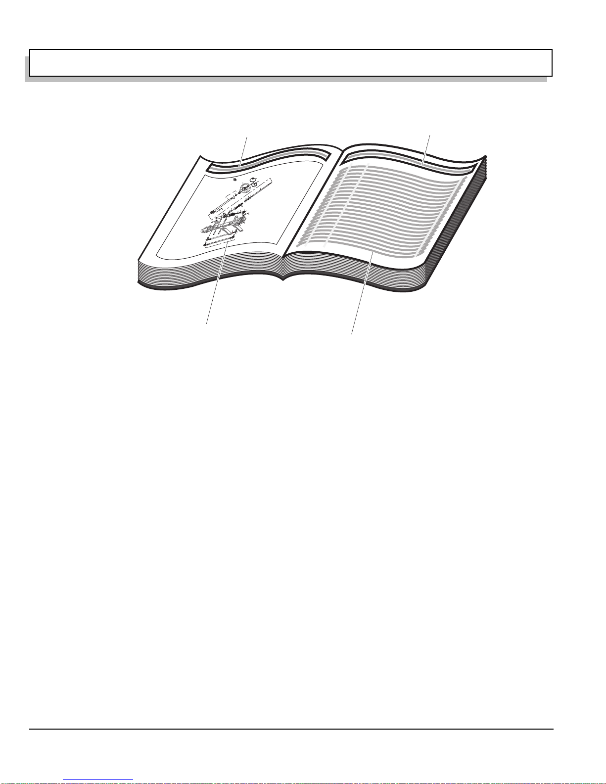
HOW TO USE THE SERVICE PARTS MANUAL . . . . . . . . . . . . . . . . . . . . . . . . . . . . . . . . . . . . . . . . . . . . . . v
ILLUSTRATED PARTS BREAKDOWN . . . . . . . . . . . . . . . . . . . . . . . . . . . . . . . . . . . . . . . . . . . . . . . . . . . . . vii
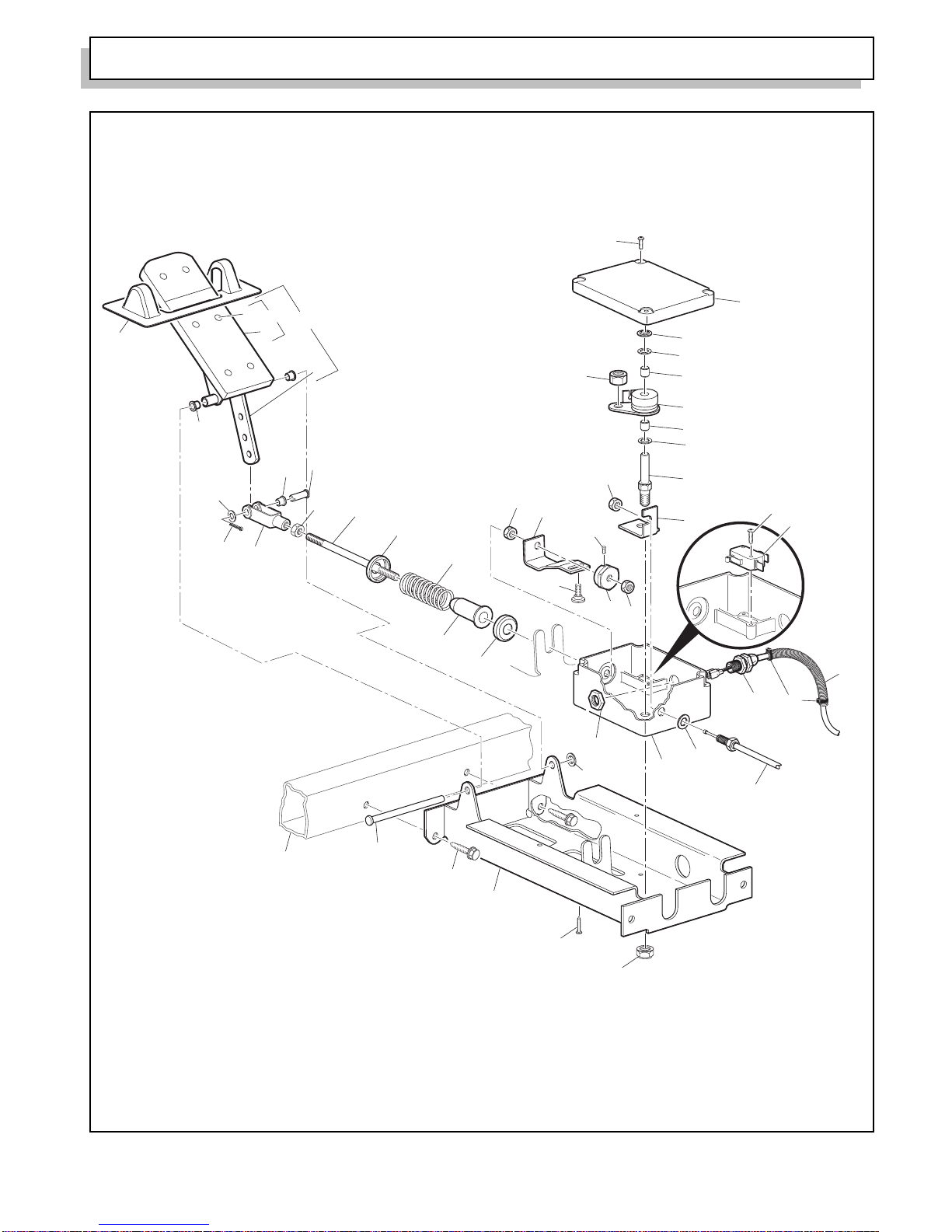
ACCELERATOR . . . . . . . . . . . . . . . . . . . . . . . . . . . . . . . . . . . . . . . . . . . . . . . . . . . . . . . . . . . . . . . . . . . . . . A-1
AIR CLEANER . . . . . . . . . . . . . . . . . . . . . . . . . . . . . . . . . . . . . . . . . . . . . . . . . . . . . . . . . . . . . . . . . . . . . . . . B-1
BODY. . . . . . . . . . . . . . . . . . . . . . . . . . . . . . . . . . . . . . . . . . . . . . . . . . . . . . . . . . . . . . . . . . . . . . . . . . . . . . . C-1
BRAKES - MECHANICAL . . . . . . . . . . . . . . . . . . . . . . . . . . . . . . . . . . . . . . . . . . . . . . . . . . . . . . . . . . . . . . . D-1
BRAKES - FRONT DISC . . . . . . . . . . . . . . . . . . . . . . . . . . . . . . . . . . . . . . . . . . . . . . . . . . . . . . . . . . . . . . . . E-1
CARBURETOR AND CHOKE . . . . . . . . . . . . . . . . . . . . . . . . . . . . . . . . . . . . . . . . . . . . . . . . . . . . . . . . . . . . F-1
CLUTCH . . . . . . . . . . . . . . . . . . . . . . . . . . . . . . . . . . . . . . . . . . . . . . . . . . . . . . . . . . . . . . . . . . . . . . . . . . . G-1
DIRECTION SELECTOR. . . . . . . . . . . . . . . . . . . . . . . . . . . . . . . . . . . . . . . . . . . . . . . . . . . . . . . . . . . . . . . . H-1
ELECTRICAL SYSTEM . . . . . . . . . . . . . . . . . . . . . . . . . . . . . . . . . . . . . . . . . . . . . . . . . . . . . . . . . . . . . . . . . J-1
ENGINE AND MUFFLER. . . . . . . . . . . . . . . . . . . . . . . . . . . . . . . . . . . . . . . . . . . . . . . . . . . . . . . . . . . . . . . . K-1
ENGINE MOUNTING. . . . . . . . . . . . . . . . . . . . . . . . . . . . . . . . . . . . . . . . . . . . . . . . . . . . . . . . . . . . . . . . . . . L-1
FRONT SUSPENSION/STEERING. . . . . . . . . . . . . . . . . . . . . . . . . . . . . . . . . . . . . . . . . . . . . . . . . . . . . . . M-1
FUEL SYSTEM . . . . . . . . . . . . . . . . . . . . . . . . . . . . . . . . . . . . . . . . . . . . . . . . . . . . . . . . . . . . . . . . . . . . . . . N-1
REAR AXLE. . . . . . . . . . . . . . . . . . . . . . . . . . . . . . . . . . . . . . . . . . . . . . . . . . . . . . . . . . . . . . . . . . . . . . . . . . P-1
REAR SUSPENSION . . . . . . . . . . . . . . . . . . . . . . . . . . . . . . . . . . . . . . . . . . . . . . . . . . . . . . . . . . . . . . . . . Q-1
SEATING . . . . . . . . . . . . . . . . . . . . . . . . . . . . . . . . . . . . . . . . . . . . . . . . . . . . . . . . . . . . . . . . . . . . . . . . . . . . R-1
STARTER / GENERATOR . . . . . . . . . . . . . . . . . . . . . . . . . . . . . . . . . . . . . . . . . . . . . . . . . . . . . . . . . . . . . . S-1
WEATHER PROTECTION . . . . . . . . . . . . . . . . . . . . . . . . . . . . . . . . . . . . . . . . . . . . . . . . . . . . . . . . . . . . . . T-1
WHEELS AND TIRES . . . . . . . . . . . . . . . . . . . . . . . . . . . . . . . . . . . . . . . . . . . . . . . . . . . . . . . . . . . . . . . . . . U-1
SPECIALTY PRODUCTS . . . . . . . . . . . . . . . . . . . . . . . . . . . . . . . . . . . . . . . . . . . . . . . . . . . . . . . . . . APPENDIX A-1

Page iv
TABLE OF CONTENTS
Service Parts Manual
Notes:

v
Service Parts Manual
This manual is divided into several sections:
•GENERAL INFORMATION
•ILLUSTRATED PARTS BREAKDOWN
•APPENDIX
The first section, GENERAL INFORMATION, contains the following information:
•WARRANTY INFORMATION
•GENERAL INDEX
•HOW TO USE THE SERVICE PARTS MANUAL
The second section, ILLUSTRATED PARTS BREAKDOWN, contains illustrations and parts lists for all systems of your
vehicle.
The third section, APPENDIX, contains a listing of specialty products and accessories.
USE OF THE MANUAL
To use this manual, consult the GENERAL INDEX to locate the information or illustration required.
Introduction of some revisions varies due to supply of components; therefore, it is possible that various combinations of
components may be found that are not directly reflected by each illustration. Consult the illustration that best suits your
situation and then contact the Service Parts Department. It is important that the serial number of your vehicle and its
model number be supplied to Service Parts when ordering any replacement components.
Locate the serial number plate (see BODY located in the Illustrated Parts Breakdown section of this manual for its loca-
tion) and note the complete number shown on the plate.
HOW TO USE THE SERVICE PARTS MANUAL

vi
HOW TO USE THE SERVICE PARTS MANUAL
Service Parts Manual
1. WHEN THE PART NUMBER IS NOT KNOWN
•Determine the function and application of the part required. Turn to the General Index and select the most appro-
priate title.
•Turn to the page number indicated and locate the desired part on the illustration.
•From the illustration, obtain the item number assigned to the desired part. Refer to the accompanying description
for specific information regarding the part.
2. IF YOU KNOW THE PART NUMBER
•Locate the part number or description in the appropriate column on the parts list page.
NOTE: It is suggested that you confirm that the part selected is correct by verifying it with the pictorial representation on
the illustrated page.
Should an asterisk (*) appear in the part number column on the parts list page, read upwards until a part number is
found. The part number is the lowest assembly sold by Service Parts and the asterisk (*) indicates that the part depicted
is not available for purchase.
NOTE: Descriptions are indented under the assembly that they are used on. That assembly is, in turn listed under the
assembly that it is used on. This process is repeated until the highest final assembly is reached.
To facilitate the maintenance and repair of the vehicle, a Technician’s Repair and Service Manual is
available from the Service Parts Department.
Title Title
Left hand illustration page
(continued on right hand page
if required)
Parts list (continued on
rear of page if required)
Front of Vehicle
123
101
100
99
98
120
74
70
71
64
63
65
66
67
121
122
114
119
115
111
73
72
112
118
116
113
62
69
94
96
95
82,87
81,86
84,89
83,88
102,104
105
79
91
92
107
106
62 - Includes Items 63 - 66, 69 - 74
70 - Includes Items 71 - 74
81 - Includes Items 82 - 84
86 - Includes Items 87 - 89
94 - Includes Items 95, 96
111 - Includes Items 112 - 114
118 - Includes Items 119 - 121
126 - Includes Items 127- 131
103
*See Body Section for
decal information
127
128129
130
131
126

Page vii
Service Parts Manual
ILLUSTRATED PARTS BREAKDOWN

Page A-1 Service Parts Manual
6
5
13
12
11
11
10
12
14
15
24
25
26
27
28
23
29
4
16
5
23
19
21
20
22
Part of
Accelerator
Cable
18
36
3
1 - Includes Items 3 - 39, 41 - 49
2 - Includes Items 3 - 37, 40 - 49 (TG5)
7
8
31
32
33
35
34
50
Part of
Frame
43
47
48
31
46 45
51
30
44
41
42
49
Ref Acl 8-1
39, 40
39, 40
ACCELERATOR

Page A-2
Service Parts Manual
98
99
86
129
130
87
88
77
76
66
81
62
64
63 107
121
111
122
123
110
120
125
126127
75
82
83
78
85 - Includes Items 86 - 96
106 - Includes Items 107 - 119
61
104
102 101
80
A
C
B
88 - Includes Items 89 - 96
94
93
91
91
90
90
92
89
95
96
B
55
54
57
58
53
66 - Includes Items 67 - 74
70
74 73
72
69 71
67 68
A
111 - Includes Items 112 - 119
113
114
115 116
112
115
117 118
119
C
103
109
108
60
Timing Belt
Cover on
Engine
Accelerator
Cable
Ref Acl 8-2
ACCELERATOR

Page A-3 Service Parts Manual
When ordering parts, please specify the model and serial number of the product.
* Indicates a component that is not available as an individual part.
G** Indicates consult Customer Service Department for additional information.
ITEM PARTNO. 12345 DESCRIPTION QTY.
1 72062-G02 PEDAL BOX ASSEMBLY (INCLUDES ITEMS 3 - 39, 41 - 49)........................... 1
2 72062-G06 PEDAL BOX ASSEMBLY (INCLUDES ITEMS 3 - 37 , 40 - 49) (TG5)................ 1
3 70116-G02 ACCELERATOR PEDAL BRACKET............................................................. 1
4 01051-G01 SCREW, #8 - 16 X 1/2" LG........................................................................... 4
5 25853-G02 PEDAL BOX AND COVER........................................................................... 1
6 00684-G6 SCREW, #8 - 32 X 3/4" LG (STAINLESS STEEL)........................................ 2
7 25861-G01 MICRO SWITCH........................................................................................... 1
8 01050-G01 SCREW, #4 - 20 X 5/8" LG........................................................................... 2
9
10 72066-G01 CONTROL ARM ........................................................................................... 1
11 23860-G1 BEARING...................................................................................................... 2
12 24621-G1 NYLON WASHER, 5/16"............................................................................... 2
13 12064-G1 PUSH NUT, 5/16".......................................................................................... 1
14 25768-G01 PIVOT ROD.................................................................................................. 1
15 72199-G01 PIVOT BRACKET......................................................................................... 1
16 14390-G1 LOCK NUT, 3/8-24........................................................................................ 1
17
18 72198-G03 MICRO SWITCH CAM.................................................................................. 1
19 15126-G1 LOCK NUT, 5/16 - 24.................................................................................... 1
20 00487-G3 SETSCREW, 1/4 - 20 X 3/8" LG................................................................... 1
21 72074-G01 CONTROL ARM LINK .................................................................................. 1
22 72225-G01 SHOULDER BOLT, #10 - 24 X 11/16" LG..................................................... 1
23 00532-G4 NUT, 5/16 - 24............................................................................................... 2
24 17677-G1 SPRING RETAINER ..................................................................................... 1
25 17979-G1 ACCELERATOR ROD BUSHING................................................................. 1
26 73046-G01 COMPRESSION SPRING............................................................................ 1
27 17677-G2 SPRING RETAINER ..................................................................................... 1
28 72072-G01 ACCELERATOR ROD .................................................................................. 1
29 10385-G4 CLEVIS YOKE (ADJUSTABLE).................................................................... 1
30 10386-G3 CLEVIS PIN, 5/16" X 13/16" LG ................................................................... 1
ACCELERATOR

When ordering parts, please specify the model and serial number of the product.
* Indicates a component that is not available as an individual part.
G** Indicates consult Customer Service Department for additional information.
ITEM PARTNO. 12345 DESCRIPTION QTY.
Page A-4
Service Parts Manual
31 17838-G1 NYLON BUSHING ........................................................................................ 3
32 17255-G1 TEFLON WASHER, 5/16"............................................................................. 1
33 10387-G3 COTTER PIN, 3/32" X 3/4" LG ..................................................................... 1
34 74432-G01 PEDAL PIVOT PIN ....................................................................................... 1
35 12064-G6 PUSH NUT, 9/32".......................................................................................... 1
36 14390-G10 LOCK NUT, #10 - 24..................................................................................... 1
37 12730-G1 WHEEL BEARING GREASE (NOT ILLUSTRATED).................................... A/R
38
39 72201-G02 WIRE HARNESS (PEDAL BOX) .................................................................. 1
40 72201-G03 WIRE HARNESS (PEDAL BOX) (TG5)........................................................ 1
41 17313-G1 FLEX LOOM (BULK)..................................................................................... AR
42 17618-G1 WIRE TIE...................................................................................................... 2
43 72402-G01 ACCELERATOR CABLE .............................................................................. 1
44 00559-G8 WASHER, 5/16"............................................................................................ 1
45 25799-G02 ACCELERATOR PEDAL ASSEMBLY (INCLUDES ITEMS 47 - 49)............. 1
46 27844-G01 ACCELERATOR PEDAL PAD KIT (INCLUDES ITEMS 47 - 48)............ 1
47 15766-G1 OVAL RIVET, 3/16" X 7/16" LG........................................................ 6
48 27512-G01 ACCELERATOR PEDAL PAD ......................................................... 1
49 * ACCELERATOR PEDAL
50 00715-G2 BOLT, 5/16 -18 X 4/5" LG.................................................................................... 4
51 70135-G01 PEDAL PIVOT COVER....................................................................................... 1
52
53 72401-G01 CHOKE CABLE (WITH NUTS) ........................................................................... 1
54 00568-G4 LOCK WASHER, 9/16"........................................................................................ 1
55 00545-G4 JAM NUT, 9/16 - 18............................................................................................. 1
56
57 72155-G01 RETAINER .......................................................................................................... 1
58 72154-G01 CHOKE CABLE ADAPTER................................................................................. 1
59
60 00544-G4 JAM NUT, 5/16 - 24............................................................................................. 2
ACCELERATOR

Page A-5 Service Parts Manual
When ordering parts, please specify the model and serial number of the product.
* Indicates a component that is not available as an individual part.
G** Indicates consult Customer Service Department for additional information.
ITEM PARTNO. 12345 DESCRIPTION QTY.
61 25737-G01 CARBURETOR LINKAGE ROD (INCLUDES ITEMS 62 - 64)............................ 1
62 23722-G1 ADJUSTING ROD (SHORT)......................................................................... 1
63 24465-G1 BALL JOINT SOCKET.................................................................................. 2
64 00526-G4 NUT, #10 - 32................................................................................................ 2
65
66 25760-G01 CARBURETOR LINKAGE BELLCRANK (INCLUDES ITEMS 67 - 74)............... 1
67 25759-G01 CARBURETOR PIVOT................................................................................. 1
68 23860-G1 BEARING...................................................................................................... 2
69 24621-G1 NYLON WASHER, 5/16"............................................................................... 2
70 25768-G01 PIVOT ROD.................................................................................................. 1
71 12064-G1 PUSH NUT, 5/16".......................................................................................... 1
72 24479-G1 BALL JOINT BALL........................................................................................ 2
73 00565-G5 LOCK WASHER, #10 ................................................................................... 2
74 00526-G4 NUT, #10 - 32................................................................................................ 2
75 72197-G01 PIVOT BRACKET................................................................................................ 1
76 14390-G1 LOCK NUT, 3/8 - 24 ............................................................................................ 1
77 00414-G8 BOLT, 1/4 - 20 X 1" LG (STAINLESS STEEL)..................................................... 2
78 14390-G4 LOCK NUT, 1/4 - 20 ............................................................................................ 2
79
80 72254-G01 THROTTLE LINKAGE ROD ASSEMBLY (INCLUDES ITEMS 81 - 83).............. 1
81 72609-G01 ADJUSTING ROD (LONG)........................................................................... 1
82 24465-G1 BALL JOINT SOCKET.................................................................................. 2
83 00526-G4 NUT, #10 - 32................................................................................................ 2
84
85 25702-G01 GOVERNOR PIVOT BRACKET ASSEMBLY (INCLUDES ITEMS 86 - 96)........ 1
86 601088 BELLCRANK BRACKET............................................................................... 1
87 14390-G1 LOCK NUT, 3/8 - 24...................................................................................... 1
88 25763-G01 GOVERNOR PIVOT ASSEMBLY (INCLUDES ITEMS 89 - 96) ................... 1
89 25762-G01 GOVERNOR PIVOT............................................................................... 1
90 23860-G1 BEARING ............................................................................................... 2
ACCELERATOR

When ordering parts, please specify the model and serial number of the product.
* Indicates a component that is not available as an individual part.
G** Indicates consult Customer Service Department for additional information.
ITEM PARTNO. 12345 DESCRIPTION QTY.
Page A-6
Service Parts Manual
91 24621-G1 NYLON WASHER, 5/16"........................................................................ 2
92 25768-G01 PIVOT ROD............................................................................................ 1
93 12064-G1 PUSH NUT, 5/16"................................................................................... 1
94 24479-G1 BALL JOINT BALL ................................................................................. 2
95 00565-G5 LOCK WASHER, #10............................................................................. 2
96 00526-G4 NUT, #10 - 32......................................................................................... 2
97
98 00276-G6 BOLT, 5/16 - 24 X 3/4" LG................................................................................... 2
99 00565-G8 LOCK WASHER, 5/16"........................................................................................ 2
100
101 25737-G03 GOVERNOR LINKAGE ROD (INCLUDES ITEMS 102 - 104)............................ 1
102 23722-G1 ADJUSTING ROD......................................................................................... 1
103 24465-G1 BALL JOINT SOCKET.................................................................................. 2
104 00526-G4 NUT, #10 - 32................................................................................................ 2
105
106 25690-G01 GOVERNOR BELLCRANK ASSEMBLY (INCLUDES ITEMS 107 - 119) ........... 1
107 25765-G01 GOVERNOR BELLCRANK........................................................................... 1
108 24479-G1 BALL JOINT BALL........................................................................................ 1
109 00734-G5 LOCK NUT, #10 - 32..................................................................................... 1
110 14390-G4 LOCK NUT, 1/4 - 20...................................................................................... 1
111 22751-G2 GOVERNOR BRACKET ASSEMBLY (INCLUDES ITEMS 112 - 119).......... 1
112 22752-G1 GOVERNOR BRACKET ........................................................................ 1
113 25274-G1 GOVERNOR ROD ................................................................................. 1
114 22754-G1 BUSHING............................................................................................... 1
115 25661-G01 CUP WASHER ....................................................................................... 2
116 23578-G1 COMPRESSION SPRING...................................................................... 1
117 22754-G2 BUSHING............................................................................................... 1
118 23859-G1 GOVERNOR ADJUSTER ...................................................................... 1
119 00526-G4 NUT, #10 - 32......................................................................................... 1
120 00491-G4 SETSCREW, 1/4 - 20 X 1/2" LG.......................................................................... 2
ACCELERATOR

Page A-7 Service Parts Manual
When ordering parts, please specify the model and serial number of the product.
* Indicates a component that is not available as an individual part.
G** Indicates consult Customer Service Department for additional information.
ITEM PARTNO. 12345 DESCRIPTION QTY.
121 25738-G01 SPRING............................................................................................................... 1
122 25286-G1 SAFETY SEAL, 3/8"............................................................................................ 1
123 12064-G3 PUSH NUT, 3/16"................................................................................................ 1
124
125 25653-G01 ACCELERATOR CABLE BRACKET................................................................... 1
126 26826-G01 LOCK WASHER, 8 MM....................................................................................... 2
127 26827-G01 NUT, M8 X 1.25 MM............................................................................................ 2
128
129 72055-G01 ACCELERATOR CABLE BRACKET................................................................... 1
130 17618-G1 WIRE TIE ............................................................................................................ 7
ACCELERATOR

Page A-8
Service Parts Manual
ACCELERATOR

Page B-1 Service Parts Manual
13
12
14
1
11 Ignition Coil
Bracket
2
5
20
Carburetor
21
6
9
7
4
26
16
18
17
7
8
R
ef Air 8
AIR CLEANER

THE USE OF NON U.L. PARTS WILL VOID ANY U.L. LISTING.
When ordering parts, please specify the model and serial number of the product.
* Indicates a component that is not available as an individual part.
G** Indicates consult Customer Service Department for additional information.
ITEM PARTNO. 12345 DESCRIPTION QTY.
Page B-2
Service Parts Manual
1 26727-G01 CARBURETOR / AIR BOX GASKET .................................................................. 2
2 26728-G01 CHOKE BRACKET.............................................................................................. 1
3
4 23726-G6 SPACER, 7/16" ................................................................................................... 4
5 72178-G02 HOUSING............................................................................................................ 1
6 00664-G7 LOCK WASHER, 1/4" (STAINLESS STEEL) ...................................................... 2
7 13632-G1 NUT, M6 X 1........................................................................................................ 4
8 72529-G01 BAFFLE............................................................................................................... 1
9 72514-G01 STUD, M6 X 1 X 39 MM LG ................................................................................ 2
10
11 72147-G01 RUBBER GROMMET.......................................................................................... 2
12 23726-G7 SPACER, 9/16" ................................................................................................... 2
13 26671-G01 BOLT AND WASHER, M6 X 1 X 30 MM LG ....................................................... 2
14 26701-G01 WASHER, 6.5 MM............................................................................................... 2
15
16 72368-G01 AIR FILTER ELEMENT ....................................................................................... 1
17 72179-G02 AIR FILTER COVER ........................................................................................... 1
18 72145-G01 LATCH................................................................................................................. 3
19
20 72146-G02 INLET COVER .................................................................................................... 1
21 00614-G5 SCREW, #8 - 18 X 5/8" LG ................................................................................. 6
22
23
24
25
26 72151-G01 PCV HOSE.......................................................................................................... 1
AIR CLEANER

Page C-1 Service Parts Manual
40
39 32
34
4
2
3
31
1
32
7
8
5
35
33
23
27
1 - Includes Items 2 - 5
14
15
11
12
16
18
21
22
20
19
9
R
ef Bod 8-1
BODY
This manual suits for next models
7
Table of contents
Other Ezgo Golf Car manuals

Ezgo
Ezgo RXV GOLF CAR User manual

Ezgo
Ezgo TXT Freedom Gasoline User manual

Ezgo
Ezgo RXV Fleet Freedom Shuttle 2+2 User manual

Ezgo
Ezgo RXV Fleet Freedom Shuttle 2+2 User manual

Ezgo
Ezgo ST SHUTTLE 4/6 2009 User manual

Ezgo
Ezgo 2Five User manual

Ezgo
Ezgo RXV EX1 EFI User manual

Ezgo
Ezgo TXT FREEDOM User manual

Ezgo
Ezgo ST 400 48V User manual

Ezgo
Ezgo TXT FREEDOM User manual
Popular Golf Car manuals by other brands

Club Car
Club Car Precedent owner's manual

Club Car
Club Car Carryall 2 2003 owner's manual

Atomic
Atomic ZIP user manual

Segway
Segway SE-3 Patroller Service manual

Electric Vehicles Oceania
Electric Vehicles Oceania FourStar Cruiser Safety instruction

Club Car
Club Car 2005 precendent Maintenance and service