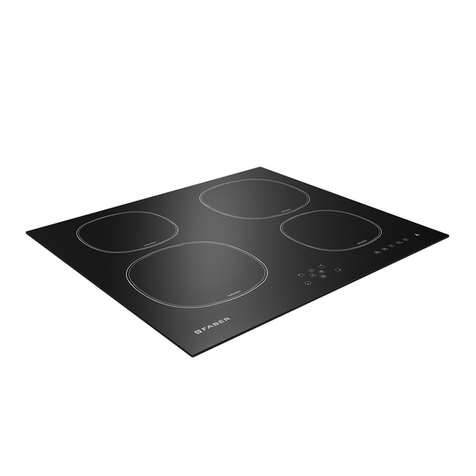
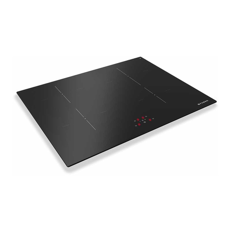
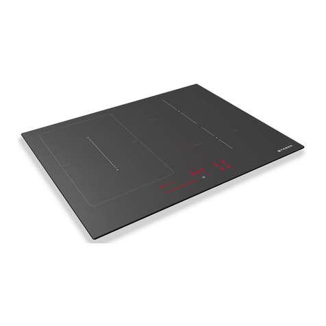
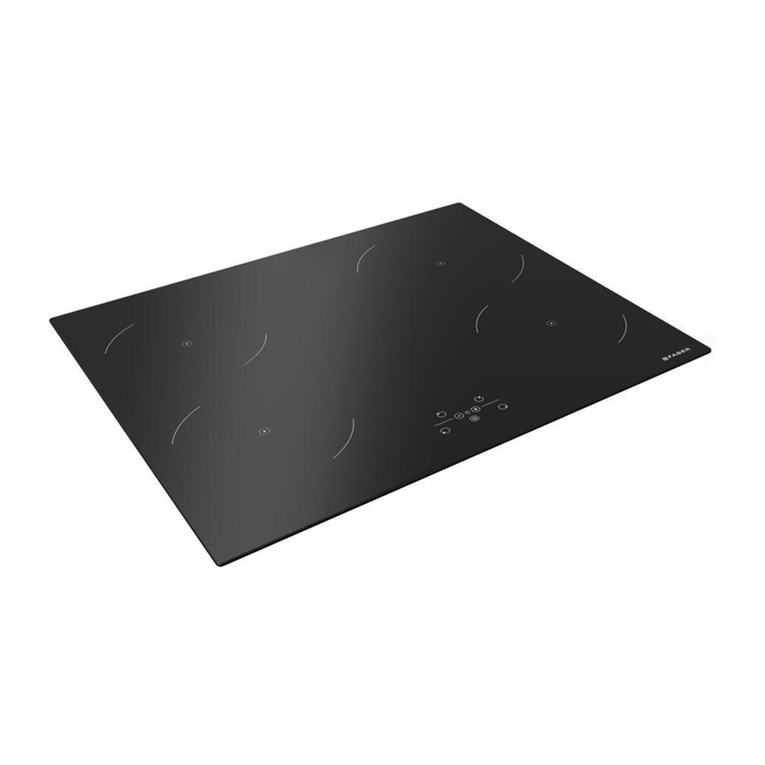
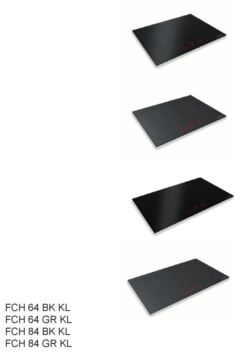
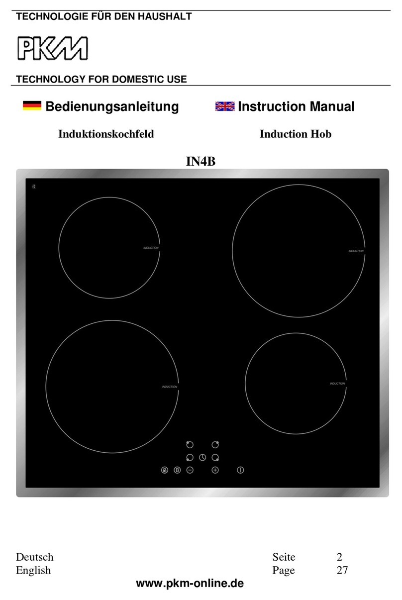
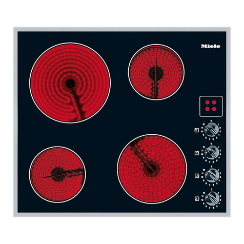
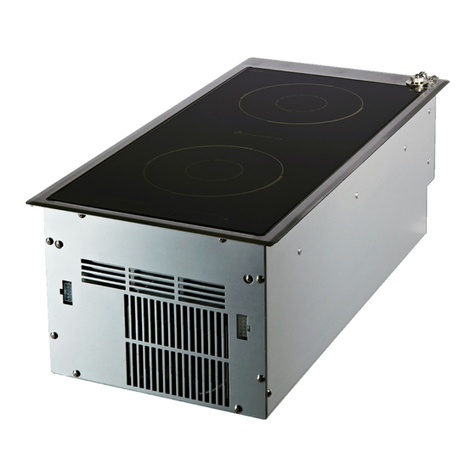
Faber FBH 64 BK User manual

EN Warning! Before proceeding with instal-
lation,
read the Recommendations and
Suggestions
in the User Manual.
DE
Achtung! Lesen Sie vor Beginn der
Installation die Sicherheitshinweise
in der Bedienungsanleitung.
CS
EL
FR
Attention! Veuillez lire les consignes de
sécurité
que contient la Notice d’utilisa-
tion avant d’installer l’appareil.
IT
Attenzione! Prima di procedere all’instal-
lazione,
leggere le Avvertenze e Suggeri-
menti contenute nel Libretto di Uso.
HR
sigurnosne informacije u Uputama za
uporabu.
PT
Atenção! Antes de continuar a instalação,
leia
as informações de segurança no Ma-
nual de Utilizado
r.
ES
¡Atención! Antes de realizar la instala-
ción,
lea la información de seguridad del
Manual del usuario.
NL
Waarschuwing! Lees de veiligheidsinfor-
matie
in de gebruikershandleiding voor-
dat u met de installatie begint.
BG
SL
PL
RO
RU
SK
UK
TR
AR
SV

EN
INSTALLATION MANUAL......................................................................................................7
DE
INSTALLATIONSANLEITUNG.............................................................................................13
FR
MANUEL D’INSTALLATION.................................................................................................19
NL
INSTALLATIEHANDLEIDING ..............................................................................................25
ES
MANUAL DE INSTALACIÓN ...............................................................................................31
PT
MANUAL DE INSTALAÇÃO.................................................................................................37
IT
MANUALE DI INSTALLAZIONE ..........................................................................................43
SV
INSTALLATIONSHANDBOK................................................................................................49
RU
.....................................................................................55
UK
........................................................................................61
CS
............................................................................................................67
SK
...........................................................................................................73
RO
MANUAL DE INSTALARE ...................................................................................................79
PL
....................................................................................................85
HR
.........................................................................................................91
SL
.............................................................................................97
EL
...........................................................................................103
TR
.......................................................................................................109
BG
......................................................................................... 115
AR
........................................................................................................................121

3
min. 20 mm
min. 20 mm
5 mm
min.
40 mm
min.
40 mm
700 mm
50 mm
5 mm
min. 20 mm
150 mm
min.
40 mm
1 2
FBH 64 BK / FCH 63 GR / FBH 84 BK / FCH 84 GR /
FBH 83 BK / FCH 83 GR / FBH 32 BK /

4
1
FBH 32 BK
3 x 1.5 mmq H05V2V2-F
220-240 V / 380-415 V 3N~ 220-240 V / 380-415 V 2N~ 220-240 V 1N~
FBH 64 BK / FCH 63 GR
4 x 2.5 mmq H05V2V2-F
220-240 V/380-415 V 3N~ 220-240 V/380-415 V 2N~ 220-240 V 1N~
4
4
3
3
Legend:
BK - black
BR - brown
BU - blue
YE/GE - yellow/green
FBH 64 BK / FCH 63 GR / FBH 84 BK / FCH 84 GR /
FBH 83 BK / FCH 83 GR / FBH 32 BK /

5
FBH 64 BK / FCH 63 GR / FBH 84 BK / FCH 84 GR /
FBH 83 BK / FCH 83 GR / FBH 32 BK /
23
FBH 84 BK / FCH 84 GR / FBH 83 BK / FCH 83 GR
5 x 2.5 mmq H05V2V2-F
220-240 V/380-415 V 3N~ 220-240 V/380-415 V 2N~ 220-240 V 1N~
34

6
A
B
FBH 64 BK
FCH 63 GR
FBH 84 BK
FCH 84 GR
C
FBH 83 BK
FCH 83 GR
D
FBH 32 BK
FBH 64 BK / FCH 63 GR / FBH 84 BK / FCH 84 GR /
FBH 83 BK / FCH 83 GR / FBH 32 BK /

7
Installation
Installation must be carried out in compliance with
current standards and regulations.
Installation must be only carried out by specialized
and licensed personnel.
Identication plate
The identication plate is located underneath the
appliance.
Cabinet requirements
The images on page 3 represent recommended
installation. If the dimensions are different, any
modications are the responsibility of the installer.
The cooking hob is intended to be built into the
worktop above a kitchen cabinet of 600 mm
width or more.
If tting in ammable material, the guidelines
and standards for low voltage installations and
for the re protection must be strictly observed.
For tted units, the components (plastic
materials and veneered wood) must be
assembled with heat-resistant adhesives (min.
100°C): Unsuitable materials and adhesives can
result in warping and detachment.
The kitchen cabinet must allow sufcient room
for the electrical connections of the appliance.
Suspended kitchen cabinets above the appliance
must be installed at a distance that provides
enough room for comfortable working process.
The use of hard wood decorative borders around
the worktop behind the appliance is allowed, in this
case the minimum distance remains as indicated on
the installation illustrations.
The minimum distance between the built-in
appliance and rear wall is indicated at the illustration
for the installation of the built-in appliance (150mm
for the side wall, 40mm for the rear and 500mm
minimum for any cabinets above it).
As shown on page 3, the appliance bottom
thickness is 55 mm.
When installed above a drawer or cabinet the
hob must be tted with a horizontal plate 20 mm
away from the worktop‘s bottom surface. When
installed above an oven it is not necessary to
add the horizontal plate. The space between the
plate and the appliance must be empty and no
objects may be stored or kept inside it.
Incorporation of the oven under the appliance is
permissible for ovens equipped with a cooling
fan.
Repair
If the power cable is damaged, it must be replaced
by the manufacturer or the service or else by a
person with similar qualications, in order to avoid
any risks.
Warning!
Before attempting any repairs on the appliance,
disconnect the power supply.
Technical data
Product identication
Type: FHSM-B2
Models: FCH 63 GR, FBH 84 BK, FCH 84 GR,
FBH 83 BK, FCH 83 GR, FBH 32 BK
Type: FHSM-B3
Models: FBH 64 BK
Refer to the data plate placed on the bottom
side of the product.
The manufacturer provides continuously product
enhancements. For this reason, the text and the
illustrations in this manual may be changed without
notice.
EN

8
Installation procedure
Explanation for positions in illustrations (page
3, 4 and 5)
1Cut-out dimension
2Kitchen furniture
3Monophase connection
4Twophase/ Triphase connection
Electrical connection
1
Refer to the information in chapter „Electrical
connection“ before connecting the appliance.
Connect the appliance like shown in the
diagram (in accordance with the mains voltage).
2
Ventilation
The illustration on page 5 show two examples
of installation suitable for proper ventilation
and one example of incorrect installation to be
avoided.
3
Hob seal
To prevent leakage of liquid between the
frame of the hob and the countertop, place the
adhesive seal provided along the entire outer
edge of the hob before assembly.
Basic adjustment of sensors to the
ambience
Upon each connection to the power supply
the sensors of the appliance are automatically
adjusted to the environment to ensure their
proper function. All displays turn on and are fully
illuminated for a few seconds.
During the adjustment procedure the sensors
must be free of any objects, otherwise the
adjustment procedure will be interrupted until
such objects are removed from the sensor
surface. During this period the regulation of the
cooktop is impossible.
Electrical connection
Connection terminals are revealed when the
connection box cover is removed.
FABER hobs are supplied with a power cable.
Make sure the characteristics of the household
electrical system (voltage, maximum power
and current) are compatible with those of the
appliance.
If the appliance is to be permanently connected to
the power supply:
Install a device that enables disconnection
from the power supply, with a contact opening
distance (3 mm) that ensures complete
disconnection in category III overvoltage
conditions.
Ensure the following:
– Check that plug and socket are correctly
dimensioned, according to the appliance rating
plate. Avoid the use of adapters and shunts as
these could cause overheating and burns.
– The plug and the socket can be easily reached
and are positioned so that no live part is
accessible when inserting or removing the plug.
– The appliance does not rest against the plug
when installed in the worktop.
– When replacing the power cable, please use
the type cable indicated in gure 1 on pages 4
and 5.
– The earthing wire must be connected to the
terminal marked with the earthing symbol.
– The connection cable must lead through the
relief safety device, protecting it from accidental
pulling out.

9
After electrical connection
Switch on all the hotplates for about 3 minutes
to check the proper function.
Power limitation settings
Power limitation setting is possible for all the
following models:
FBH 64 BK, FCH 63 GR, FBH 84 BK,
FCH 84 GR, FBH 83 BK, FCH 83 GR.
–Setting is possible only during the rst two
minutes after plug in the appliance.
– The touch has to be unlocked and all heaters
have to be switched off.
– The factory power setting is the maximum level.
– If there is a black out, power level set remains
unchanged.
Example of power limitation setting of a four cooking
zones hob (FBH 64 BK / FBH 84 BK / FCH 84 GR):
Press at the same time all the four cooking
zones and hold it until you can hear a signal.
88
88
If you can‘t hear the signal within 10 seconds,
repeat the operation trying to better position the
ngers.
You can now switch with and
between the power limitation levels
(2,8 kW, 3,5 kW and MAX).
28
88
74
88
Note: If, after setting the power level, you don‘t
proceed to conrm with the nger touch and the
subsequent signal within 60 seconds, the new
setting will not be acquired by the hob.
Example of power limitation setting of a three
cooking zones hob
(FCH 63 GR / FBH 83 BK / FCH 83 GR):
Press at the same time all the three cooking
zones and hold it until you can hear a signal.
8
88
8
If you can‘t hear the signal within 10 seconds,
repeat the operation trying to better position the
ngers.
You can now switch with and between
the power limitation levels
(2,8 kW, 3,5 kW and MAX).
2
88
8
7
88
4

10
Press now at the same time all the three
cooking zones and hold it until you can hear a
signal for conrmation of the power set.
2
88
8
Note: If, after setting the power level, you don‘t
proceed to conrm with the nger touch and the
subsequent signal within 60 seconds, the new
setting will not be acquired by the hob.
MODEL FBH 64 BK FCH 63 GR FBH 84 BK
FCH 84 GR FBH 83 BK
FCH 83 GR FBH 32 BK
DISPLAY
SETTING
MAX
POWER
TOTAL
MAX
POWER
TOTAL
MAX
POWER
TOTAL
MAX
POWER
TOTAL
MAX
POWER
TOTAL
2,8 2,8 kW 2,8 kW 2,8 kW 2,8 kW
3,4 kW3,5 3,5 kW 3,5 kW 3,5 kW 3,5 kW
7,4 - MAX 6,75 kW 6,9 kW 7,1 kW 6,4 kW
Power in kW @ 230V - 50/60 Hz
FBH 64 BK
1
2
3
4
1 Cooking zone 1
2 Cooking zone 2
3 Cooking zone 3
4 Cooking zone 4
Parameter Valore Dimensioni (mm)
Working dimensions
(W x D) -580 ×520
Tensione/frequenza di
alimentazione 220-240 V, 50/60 Hz -
Power and heating element values
Cooking zone 1 1400 W;
Power Booster: 1850 W Ø 175
Cooking zone 2 1400 W Ø 175
Cooking zone 3 1850 W;
Power Booster: 2100 W Ø 215
Cooking zone 4 1400 W Ø 175
Parameter Symbol Value Unit of measure
Appliance weight M8,5 / 10,5 kg
Number of cooking zones 4
Heat source of each
cooking zone induction

11
FCH 63 GR
2
1
3
1 Cooking zone 1
2 Cooking zone 2
3 Cooking zone 3
Parameter Valore Dimensioni (mm)
Working dimensions
(W x D) -580 ×520
Tensione/frequenza di
alimentazione 220-240 V, 50/60 Hz -
Power and heating element values
Cooking zone 1 1400 W;
Power Booster: 2000 W Ø 175
Cooking zone 2 1400 W Ø 175
Cooking zone 3
2300 W; Power
Booster: 3000 W
3000 W; Power
Booster: 3600 W
Ø 230
Ø 230 DZ
Parameter Symbol Value Unit of measure
Appliance weight M11 / 13 kg
Number of cooking zones 3
Heat source of each
cooking zone induction
FBH 84 BK / FCH 84 GR
3
4
1
2
1 Cooking zone 1
2 Cooking zone 2
3 Cooking zone 3
4 Cooking zone 4
Parameter Valore Dimensioni (mm)
Working dimensions
(W x D) -780 ×520
Tensione/frequenza di
alimentazione 220-240 V, 50/60 Hz -
Power and heating element values
Cooking zone 1 1200 W; Power Booster:
1400 W Ø 175
Cooking zone 2 2300 W; Power Booster:
3000 W Ø 215
Cooking zone 3 1400 W; Power
Booster: 2000 W Ø 175
Cooking zone 4 1400 W Ø 175
Parameter Symbol Value Unit of measure
Appliance weight M12,5 / 14,5 kg
Number of cooking zones 4
Heat source of each
cooking zone induction

12
FBH 83 BK / FCH 83 GR
1
2
3
1 Cooking zone 1
2 Cooking zone 2
3 Cooking zone 3
Parameter Valore Dimensioni (mm)
Working dimensions
(W x D) -780 ×400
Tensione/frequenza di
alimentazione 220-240 V, 50/60 Hz -
Power and heating element values
Cooking zone 1 1400 W; Power Booster:
2000 W Ø 175
Cooking zone 2 1400 W Ø 175
Cooking zone 3 2300 W; Power
Booster: 3000 W Ø 265
Parameter Symbol Value Unit of measure
Appliance weight M10,6 / 12,6 kg
Number of cooking zones 3
Heat source of each
cooking zone induction
FBH 32 BK
1
2
1 Cooking zone 1
2 Cooking zone 2
Parameter Valore Dimensioni (mm)
Working dimensions
(W x D) -320 ×520
Tensione/frequenza di
alimentazione 220-240 V, 50/60 Hz -
Power and heating element values
Cooking zone 1 1400 W; Power Booster:
2000 W Ø 175
Cooking zone 2 1200 W; Power Booster:
1400 W Ø 175
Parameter Symbol Value Unit of measure
Appliance weight M6 / 8 kg
Number of cooking zones 2
Heat source of each
cooking zone induction

13
DE
Installation
Installationen müssen gemäß aktuellen Standards
und Richtlinien ausgeführt werden.
Installationen dürfen nur von Fachpersonal
ausgeführt werden.
Typenschild
Das Typenschild ist unter dem Gerät angebracht.
Anforderungen an den Küchenschrank
In den Abbildungen auf Seite 3 ist die empfohlene
Installation dargestellt. Sollten die Abmessungen
abweichen, müssen etwaige Anpassungen vom
Installateur durchgeführt werden.
Das Kochfeld ist für den Einbau in eine
Arbeitsplatte über einem mindestens 600 mm
breiten Küchenschrank bestimmt.
Bei Einbau in brennbares Material
müssen die Richtlinien und Standards
für Niederspannungsanlagen und zum
Brandschutz unbedingt eingehalten werden.
Bei montierten Einheiten müssen die
Komponenten (Kunststoff und Furnierholz)
mit hitzebeständigem Klebstoff (min. 100 °C)
montiert werden: Ungeeignete Materialien und
Klebstoffe können sich verziehen und ablösen.
Der Küchenschrank muss über ausreichend
Raum für die elektrischen Anschlüsse des
Geräts verfügen. Hängende Küchenelemente
über dem Gerät müssen in einem Abstand
installiert sein, der genügend Raum für
angenehme Arbeitsbedingungen bietet.
Die Verwendung von Abschlussleisten aus Hartholz
entlang der Arbeitsplatte hinter dem Gerät ist
zulässig, wenn der Mindestabstand entsprechend
den Angaben auf den Installationsabbildungen
eingehalten wird.
Der Mindestabstand zwischen dem Einbaugerät
und der Rückwand ist auf der Abbildung für die
Installation des Einbaugeräts angegeben (150 mm
für die Seitenwand, 40 mm für die Rückseite und
mindestens 500 mm für jedes Möbelstück darüber).
Wie auf Seite 3 dargestellt, beträgt die Dicke des
Gerätebodens 55 mm.
Bei einer Schublade oder einem anderen
Küchenschrank muss unter dem Kochfeld
ein Zwischenboden in 20 mm Abstand zur
Unterseite der Arbeitsplatte eingebaut werden.
Bei einem Ofen ist es nicht notwendig, den
Zwischenboden einzubauen. Der Raum
zwischen dem Boden und dem Gerät muss
leer sein. Es dürfen keine Gegenstände darin
gelagert oder aufbewahrt werden.
Der Einbau eines Ofens unter dem Gerät ist
zulässig, wenn der Ofen über ein Kühlgebläse
verfügt.
Reparatur
Falls das Netzkabel beschädigt ist, muss es vom
Hersteller, dem Kundendienst oder aber einer
anderen Person mit entsprechender Qualikation
ersetzt werden, um jegliche Gefahren zu vermeiden.
Warnung!
Vor der Durchführung von Reparaturen muss
das Gerät von der Stromversorgung getrennt
werden.
Technische Daten
Produktkennzeichnung
Typ: FHSM-B2
Modell: FCH 63 GR, FBH 84 BK, FCH 84 GR,
FBH 83 BK, FCH 83 GR, FBH 32 BK
Typ: FHSM-B3
Modell: FBH 64 BK
Die technischen Daten nden Sie auf dem
Typenschild auf der Unterseite Ihres Produkts.
Der Hersteller bietet laufend
Produktverbesserungen. Daher bleiben
Änderungen an den Texten und Bildern in dieser
Bedienungsanleitung vorbehalten.

14
Installationsablauf
Erläuterung der Positionen in den Abbildungen
(Seite 3, 4 und 5)
1Ausfräsmaß
2Küchenschrank
3Dreiphasiger Netzanschluss
4Zweiphasiger/ Einphasiger
Netzanschluss
Elektrischer Anschluss
1
Lesen Sie das Kapitel „Elektrischer Anschluss“,
bevor Sie das Gerät anschließen.
Schließen Sie das Gerät wie in der Abbildung
dargestellt an (entsprechend der Netzspannung).
2
Belüftung
Auf den Seiten 5 sind zwei Beispiele für
Installationen dargestellt, die für eine
ordnungsgemäße Belüftung geeignet sind,
sowie ein Beispiel für eine unangemessene
Installation, die zu vermeiden ist.
3
Kochfelddichtung
Um zu vermeiden, dass Flüssigkeiten zwischen
den Rand des Kochfelds und die Arbeitsplatte
laufen, bringen Sie vor dem Einbau die
mitgelieferte Klebedichtung um den gesamten
äußeren Rand des Kochfelds an.
Grundlegende Anpassung der Sensoren an
die Umgebung
Bei jedem Anschluss an die Stromversorgung
passen sich die Sensoren des Geräts
automatisch an die Umgebung an, um die
einwandfreie Funktion zu gewährleisten. Alle
Anzeigen schalten sich ein und leuchten
einige Sekunden lang in voller Stärke.
Während des Anpassungsvorgangs dürfen
die Sensoren nicht durch Gegenstände
verdeckt sein, ansonsten unterbricht der
Vorgang solange, bis die Gegenstände von
der Sensoräche entfernt wurden. In dieser
Zeit kann das Kochfeld nicht bedient werden.
Elektrischer Anschluss
Die Anschlussklemmen benden sich unter der
Abdeckung der Anschlussdose.
FABER Kochfelder werden mit einem Netzkabel
geliefert.
Stellen Sie sicher, dass die Kenndaten des
elektrischen Versorgungssystems im Haus
(Netzspannung, maximale Leistung und
Stromstärke) mit denen des Geräts kompatibel
sind.
Falls das Gerät permanent mit der Stromquelle
verbunden sein soll:
Bauen Sie eine Vorrichtung ein, die die
vollständige Trennung von der Stromquelle
mit einem Kontaktöffnungsabstand (3 mm)
ermöglicht (gemäß Überspannungskategorie III).
Stellen Sie Folgendes sicher:
– Prüfen Sie, dass Stecker und Steckdose gemäß
dem Gerätetypenschild angemessen sind.
Vermeiden Sie den Einsatz von Adaptern und
Nebenanschlüssen, da diese Überhitzung und
Durchglühen verursachen können.
– Stecker und Steckdose sind gut erreichbar
und so positioniert, dass keine stromführenden
Teile zugänglich sind, wenn Sie den Stecker
einstecken oder entfernen.
– Das Gerät bendet sich nicht zu nahe am
Stecker und berührt diesen nicht, wenn es in
der Arbeitsplatte eingebaut wurde.
– Verwenden Sie beim Ersetzen des Stromkabels
die in Abbildung 1 auf den Seiten 4 und 5
angegebenen Kabelarten.

15
– Die Erdungsleitung muss an die mit
dem Erdungssymbol gekennzeichnete
Anschlussklemme angeschlossen werden.
– Das Anschlusskabel muss durch die
Zugentlastung geführt werden, damit es nicht
versehentlich herausgezogen wird.
Nach dem elektrischen Anschluss
Schalten Sie alle Kochplatten für ca. 3 Minuten
ein, um sie auf ihre Funktion zu überprüfen.
Einstellung einer Leistungsbegrenzung
Für folgende Modelle kann eine
Leistungsbegrenzung eingestellt werden:
FBH 64 BK, FCH 63 GR, FBH 84 BK,
FCH 84 GR, FBH 83 BK, FCH 83 GR.
–Die Einstellung kann lediglich während der
ersten zwei Minuten nach dem Anschließen
des Geräts erfolgen.
– Das Touchfeld muss entsperrt und alle
Heizeinheiten müssen ausgeschaltet sein.
– Die werksseitige Leistungseinstellung entspricht
der größtmöglichen Stufe.
– Bei einem Stromausfall bleibt die eingestellte
Leistungsstufe unverändert.
Beispiel der Einstellung einer Leistungsbegrenzung
für ein Kochfeld mit vier Kochzonen (FBH 64 BK /
FBH 84 BK / FCH 84 GR):
Drücken Sie gleichzeitig die Tasten für alle vier
Kochzonen und halten Sie sie gedrückt, bis Sie
einen Signalton hören.
88
88
Hören Sie innerhalb von 10 Sekunden keinen
Signalton, wiederholen Sie den Vorgang und
versuchen Sie dabei, die Finger besser zu
platzieren.
Anschließend können Sie über die Tasten
und zwischen den Stufen der
Leistungsbegrenzung wechseln (2,8 kW, 3,5
kW und MAX).
28
88
74
88
Drücken Sie erneut gleichzeitig die Tasten
für alle vier Kochzonen und halten Sie sie
gedrückt, bis Sie einen Signalton hören, der die
Einstellung bestätigt.
28
88
Hinweis: Wenn Sie innerhalb von 60 Sekunden
nach Einstellen der Leistungsstufe die Tasten
nicht erneut drücken und auf den Signalton
zur Bestätigung warten, werden die neuen
Einstellungen nicht auf das Kochfeld angewendet.
Beispiel der Einstellung einer Leistungsbegrenzung
für ein Kochfeld mit drei Kochzonen:
(FCH 63 GR / FBH 83 BK / FCH 83 GR):
Drücken Sie gleichzeitig die Tasten für alle drei
Kochzonen und halten Sie sie gedrückt, bis Sie
einen Signalton hören.

16
8
88
8
Hören Sie innerhalb von 10 Sekunden keinen
Signalton, wiederholen Sie den Vorgang und
versuchen Sie dabei, die Finger besser zu
platzieren.
Anschließend können Sie über die Tasten
und zwischen den Stufen der
Leistungsbegrenzung wechseln (2,8 kW, 3,5
kW and MAX).
2
88
8
7
88
4
Drücken Sie gleichzeitig die Tasten für alle drei
Kochzonen und halten Sie sie gedrückt, bis Sie
einen Signalton hören.
2
88
8
Hinweis: Wenn Sie innerhalb von 60 Sekunden
nach Einstellen der Leistungsstufe die Tasten
nicht erneut drücken und auf den Signalton
zur Bestätigung warten, werden die neuen
Einstellungen nicht auf das Kochfeld angewendet.
MODELL FBH 64 BK FCH 63 GR FBH 84 BK
FCH 84 GR FBH 83 BK
FCH 83 GR FBH 32 BK
Bildschirm -
einstellung
Maximale
Leistung
Insgesamt
Maximale
Leistung
Insgesamt
Maximale
Leistung
Insgesamt
Maximale
Leistung
Insgesamt
Maximale
Leistung
Insgesamt
2,8 2,8 kW 2,8 kW 2,8 kW 2,8 kW
3,4 kW3,5 3,5 kW 3,5 kW 3,5 kW 3,5 kW
7,4 - MAX 6,75 kW 6,9 kW 7,1 kW 6,4 kW
Leistung in kW @ 230V - 50/60 Hz
FBH 64 BK
1
2
3
4
1 Kochzone 1
2 Kochzone 2
3 Kochzone 3
4 Kochzone 4
Parameter Wert Maße (mm)
Einbaumaße -580 ×520
Stromversorgung
(Spannung /
Frequenz) 220-240 V, 50/60 Hz -
Werte der Leistungs- und Heizelemente
Kochzone 1 1400 W;
Power Booster: 1850 W Ø 175
Kochzone 2 1400 W Ø 175
Kochzone 3 1850 W;
Power Booster: 2100 W Ø 215
Kochzone 4 1400 W Ø 175
Parameter Symbol Wert Maßeinheit
Gerätegewicht M8,5 / 10,5 kg
Anzahl der Kochzonen 4
Wärmequelle Induktion

17
FCH 63 GR
2
1
3
1 Kochzone 1
2 Kochzone 2
3 Kochzone 3
Parameter Wert Maße (mm)
Einbaumaße -580 ×520
Stromversorgung
(Spannung /
Frequenz) 220-240 V, 50/60 Hz -
Werte der Leistungs- und Heizelemente
Kochzone 1 1400 W;
Power Booster: 2000 W Ø 175
Kochzone 2 1400 W Ø 175
Kochzone 3
2300 W; Power
Booster: 3000 W
3000 W; Power
Booster: 3600 W
Ø 230
Ø 230 DZ
Parameter Symbol Wert Maßeinheit
Gerätegewicht M11 / 13 kg
Anzahl der Kochzonen 3
Wärmequelle Induktion
FBH 84 BK / FCH 84 GR
3
4
1
2
1 Kochzone 1
2 Kochzone 2
3 Kochzone 3
4 Kochzone 4
Parameter Wert Maße (mm)
Einbaumaße -780 ×520
Stromversorgung
(Spannung /
Frequenz) 220-240 V, 50/60 Hz -
Werte der Leistungs- und Heizelemente
Kochzone 1 1200 W; Power Booster:
1400 W Ø 175
Kochzone 2 2300 W; Power Booster:
3000 W Ø 215
Kochzone 3 1400 W; Power
Booster: 2000 W Ø 175
Kochzone 4 1400 W Ø 175
Parameter Symbol Wert Maßeinheit
Gerätegewicht M12,5 / 14,5 kg
Anzahl der Kochzonen 4
Wärmequelle Induktion

18
FBH 83 BK / FCH 83 GR
1
2
3
1 Kochzone 1
2 Kochzone 2
3 Kochzone 3
Parameter Wert Maße (mm)
Einbaumaße -780 ×400
Stromversorgung
(Spannung /
Frequenz) 220-240 V, 50/60 Hz -
Werte der Leistungs- und Heizelemente
Kochzone 1 1400 W; Power Booster:
2000 W Ø 175
Kochzone 2 1400 W Ø 175
Kochzone 3 2300 W; Power
Booster: 3000 W Ø 265
Parameter Symbol Wert Maßeinheit
Gerätegewicht M10,6 / 12,6 kg
Anzahl der Kochzonen 3
Wärmequelle Induktion
FBH 32 BK
1
2
1 Kochzone 1
2 Kochzone 2
Parameter Wert Maße (mm)
Einbaumaße -320 ×520
Stromversorgung
(Spannung /
Frequenz) 220-240 V, 50/60 Hz -
Werte der Leistungs- und Heizelemente
Kochzone 1 1400 W; Power Booster:
2000 W Ø 175
Kochzone 2 1200 W; Power Booster:
1400 W Ø 175
Parameter Symbol Wert Maßeinheit
Gerätegewicht M6 / 8 kg
Anzahl der Kochzonen 2
Wärmequelle Induktion

19
FR
Comme illustré en page 3, l’épaisseur inférieure de
l’appareil est de 55 mm.
L‘appareil peut être intégré dans des plans de
travail de 35 à 65 mm d‘épaisseur. Dans le cas
d‘un tiroir ou de tout autre meuble de cuisine,
la plaque à induction doit être équipée d‘une
plaque horizontale située à 20 mm de la surface
inférieure du plan de travail. En présence d‘un
four, il n‘est pas nécessaire d‘ajouter la plaque
horizontale. L’espace entre la plaque et l‘appareil
doit rester vide et rien ne doit être stocké ou
conservé dans cet espace.
Il est possible d’intégrer un four sous l‘appareil
seulement s‘il est équipé d‘un ventilateur de
refroidissement.
Réparation
Si le câble d‘alimentation est endommagé, il doit
être remplacé par le fabricant ou le SAV ou par une
personne disposant de qualications similaires, an
d‘éviter tout risque.
Avertissement !
Avant d’essayer de réparer l’appareil,
débranchez l‘alimentation.
Caractéristiques techniques
Identication du produit
Type: FHSM-B2
Modèles: FCH 63 GR, FBH 84 BK, FCH 84 GR,
FBH 83 BK, FCH 83 GR, FBH 32 BK
Type: FHSM-B3
Modèles: FBH 64 BK
Reportez-vous à la plaque du fabricant sur le
produit.
Le fabricant fournit des améliorations de produits
en permanence. Pour cette raison, le texte et les
illustrations de ce manuel peuvent être modiés
sans préavis.
Installation
L‘installation doit être effectuée en conformité avec
les normes et réglementations actuelles.
L‘installation doit être effectuée exclusivement par du
personnel spécialisé et autorisé.
Plaque d’identication
La plaque d‘identication se trouve sous l‘appareil.
Exigences pour le meuble
Les images de la page 3 illustrent l‘installation
recommandée. Si les dimensions diffèrent, les
éventuelles modications doivent être gérées par le
technicien.
La plaque à induction doit être intégrée dans
le plan de travail au-dessus d‘un élément de
cuisine d‘une largeur de 600 mm ou plus.
Si le raccord est en matériau inammable, il
convient de respecter strictement les directives
et les normes relatives aux installations basse
tension et à la protection incendie.
Pour les unités encastrées, les composants
(plastiques et contreplaqué) doivent être
assemblés à l‘aide d‘adhésifs résistants à la
chaleur (min. 100 °C) : L‘utilisation de matériaux
et adhésifs inadéquats peut provoquer une
déformation et un détachement.
L‘élément de cuisine doit laisser assez d‘espace
pour permettre le branchement de l‘appareil.
Les éléments de cuisine suspendus au-dessus
de l’appareil doivent être installés à une distance
laissant sufsamment de place pour cuisiner
confortablement.
Vous pouvez utiliser des bordures de bois décoratif
autour du plan de travail et derrière l’appareil, dès
lors que la distance minimum indiquée sur les
illustrations d‘installation est respectée.
La distance minimale entre le dispositif intégré
et le mur arrière est indiquée sur l‘illustration de
l‘installation de l‘appareil intégré (150 mm pour la
paroi latérale, 40 mm sur le dos et minimum 500
mm pour n’importe quel meuble situé au-dessus).

20
Au cours de la procédure de réglage,
les capteurs doivent être libres de tout
objet, sinon la procédure de réglage est
interrompue jusqu‘à ce que ces objets soient
retirés de la surface du capteur. Pendant ce
temps, le réglage de la table de cuisson est
impossible.
Raccordement électrique
Les bornes de raccordement sont visibles lorsque le
couvercle du boîtier de raccordement est retiré.
Les plaques à induction FABER sont livrées avec un
câble d‘alimentation.
Assurez-vous que les caractéristiques du circuit
électrique domestique (tension, puissance
maximale et courant) sont compatibles avec
celles de l‘appareil.
Si l‘appareil doit rester branché en permanence :
Installez un dispositif permettant de
débrancher l‘alimentation, avec une distance
d‘ouverture des contacts (3 mm) permettant le
débranchement complet dans les conditions de
surtension de catégorie III.
Assurez-vous des points suivants :
– Vériez que la che et la prise soient de
dimensions appropriées, selon la plaque
signalétique de l’appareil. Évitez l’utilisation
d’adaptateurs et de dérivations étant donné
qu’ils pourraient causer une surchauffe et des
brûlures.
– La che et la prise sont accessibles facilement
et sont placées de façon qu‘aucune partie sous
tension ne soit accessible lors de l‘insertion et
du retrait de la che.
– L‘appareil ne doit pas reposer contre la prise de
courant une fois installé dans le plan de travail.
– Lors du remplacement du câble d’alimentation,
utilisez le type de câble indiqué sur la gure 1
en pages 4 et 5.
Procédure d‘installation
Explication des repères sur les illustrations
(pages 3, 4 et 5)
1Dimensions de l’ouverture
2Meuble de cuisine
3Branchement triphasé
4Branchement triphasé/ monophasé
Raccordement électrique
1
Reportez-vous aux informations du chapitre
« Connexion électrique » avant de brancher
l‘appareil.
Connectez l‘appareil comme illustré dans le
diagramme (conformément à la tension de
secteur).
2
Ventilation
Les illustrations en pages 5 présentent deux
exemples d’installations adaptées pour une
ventilation correcte et un exemple d’installation
incorrecte à éviter.
3
Joint de plaque
An d’éviter l’écoulement de liquide entre le
cadre de la plaque et le comptoir, positionnez le
joint adhésif fourni le long de la bordure externe
de la plaque avant l’assemblage
Réglage de base des capteurs d‘ambiance
A chaque connexion à l‘alimentation, les
capteurs de l‘appareil sont automatiquement
ajustés à l‘environnement an de s‘assurer de
leur bon fonctionnement. Tous les afchages
s’allument et restent allumés pendant quelques
secondes.
Other manuals for FBH 64 BK
3
This manual suits for next models
6
Table of contents
Other Faber Hob manuals

Faber
Faber Solido FCH 32 User manual

Faber
Faber FBH 64 BK User manual

Faber
Faber FCH64 User manual

Faber
Faber FCH93 User manual

Faber
Faber FCH32 C User manual

Faber
Faber FCH 64 BK KL User manual

Faber
Faber FCC XERA SF20 Assembly instructions

Faber
Faber FBH 64 BK User manual

Faber
Faber FBH 64 BK User manual

Faber
Faber Vitro FCC XERA MF30 Assembly instructions