NS.557
N.560
N.610
N.620
15 bars maxi/20°C
10 bars maxi/60°C
600 l/mn mini
WV.1102-00
WV.1102-00
GARANTIE
GUARANTEE
GARANZIA
GARANTIA 1
ANS
YEARS
JAHRE
JAAR
ANNI
ANOS
DECLARATION DE CONFORMITE A LA DIRECTIVE "MACHINES"
(Directives 89/392/CEE modifiée)
et aux réglementations prises pour sa transposition
DECLARATION DE CONFORMITE A LA DIRECTIVE "MACHINES"
DECLARATION DE CONFORMITE A LA DIRECTIVE "MACHINES"
DECLARATION DE CONFORMITE A LA DIRECTIVE "MACHINES"
DECLARATION DE CONFORMITE A LA DIRECTIVE "MACHINES"
DECLARATION DE CONFORMITE A LA DIRECTIVE "MACHINES"
6 et 8, rue Gustave Eiffel - 91423 Morangis
Tél. : (16-1) 64.54.45.45
Fax : (16-1) 69.09.60.93
XXXXXXXXX XXXXXXXXXXXXXXXX XXXXXXXXXXXXXXXX XXXXXXXXXXXX XXX
XXXXXXXXX XXXXXXXXXXXXXXXX XXXXXXXXXXXXXXXX XXXXXXXXXXXX XXX
XXXXXXXXX XXXXXXXXXXXXXXXX XXXXXXXXXXXXXXXX XXXXXXXXXXXX XXX
XXXXXXXXX XXXXXXXXXXXXXXXX XXXXXXXXXXXXXXXX XXXXXXXXXXXX XXX
XXXXXXXXX XXXXXXXXXXXXXXXX XXXXXXXXXXXXXXXX XXXXXXXXXXXX XXX
XXXXXXXXX XXXXXXXXXXXXXXXX XXXXXXXXXXXXXXXX XXXXXXXXXXXX XXX
XXXXXXXXX XXXXXXXXXXXXXXXX XXXXXXXXXXXXXXXX XXXXXXXXXXXX XXX
XXXXXXXXX XXXXXXXXXXXXXXXX XXXXXXXXXXXXXXXX XXXXXXXXXXXX XXX
XXXXXXXXX XXXXXXXXXXXXXXXX XXXXXXXXXXXXXXXX XXXXXXXXXXXX XXX
XXXXXXXXX XXXXXXXXXXXXXXXX XXXXXXXXXXXXXXXX XXXXXXXXXXXX XXX
XXXXXXXXX XXXXXXXXXXXXXXXX XXXXXXXXXXXXXXXX XXXXXXXXXXXX XXX
XXXXXXXXX XXXXXXXXXXXXXXXX XXXXXXXXXXXXXXXX XXXXXXXXXXXX XXX
XXXXXXXXX XXXXXXXXXXXXXXXX XXXXXXXXXXXXXXXX XXXXXXXXXXXX XXX
XXXXXXXXX XXXXXXXXXXXXXXXX XXXXXXXXXXXXXXXX XXXXXXXXXXXX XXX
XXXXXXXXX XXXXXXXXXXXXXXXX XXXXXXXXXXXXXXXX XXXXXXXXXXXX XXX
XXXXXXXXX XXXXXXXXXXXXXXXX XXXXXXXXXXXXXXXX XXXXXXXXXXXX XXX
XXXXXXXXX XXXXXXXXXXXXXXXX XXXXXXXXXXXXXXXX XXXXXXXXXXXX XXX
XXXXXXXXX XXXXXXXXXXXXXXXX XXXXXXXXXXXXXXXX XXXXXXXXXXXX XXX
XXXXXXXXX XXXXXXXXXXXXXXXX XXXXXXXXXXXXXXXX XXXXXXXXXXXX XXX
XXXXXXXXX XXXXXXXXXXXXXXXX XXXXXXXXXXXXXXXX XXXXXXXXXXXX XXX
XXXXXXXXX XXXXXXXXXXXXXXXX XXXXXXXXXXXXXXXX XXXXXXXXXXXX XXX
XXXXXXXXX XXXXXXXXXXXXXXXX XXXXXXXXXXXXXXXX XXXXXXXXXXXX XXX
XXXXXXXXX XXXXXXXXXXXXXXXX XXXXXXXXXXXXXXXX XXXXXXXXXXXX XXX
XXXXXXXXX XXXXXXXXXXXXXXXX XXXXXXXXXXXXXXXX XXXXXXXXXXXX XXX
Le Responsable Qualité FACOM
WV.1102
Notice d'instructions
Instruction manual
Bedienungsanleitung
Gebruiksaanwijzing
Guia de instrucciones
Istruzioni per l'utilizzo
NU-WV.1102
Pompehydro-
pneumatique
Hydropneumatic
pump
Hydropneumatishe
pumpe
Hydropneumatiche
pomp
Bomba
hidroneumatica
Pompa
idropneumatica
+
WA.1165 WA.21
WA.1166F02
WA.1166FSB
NBB.103
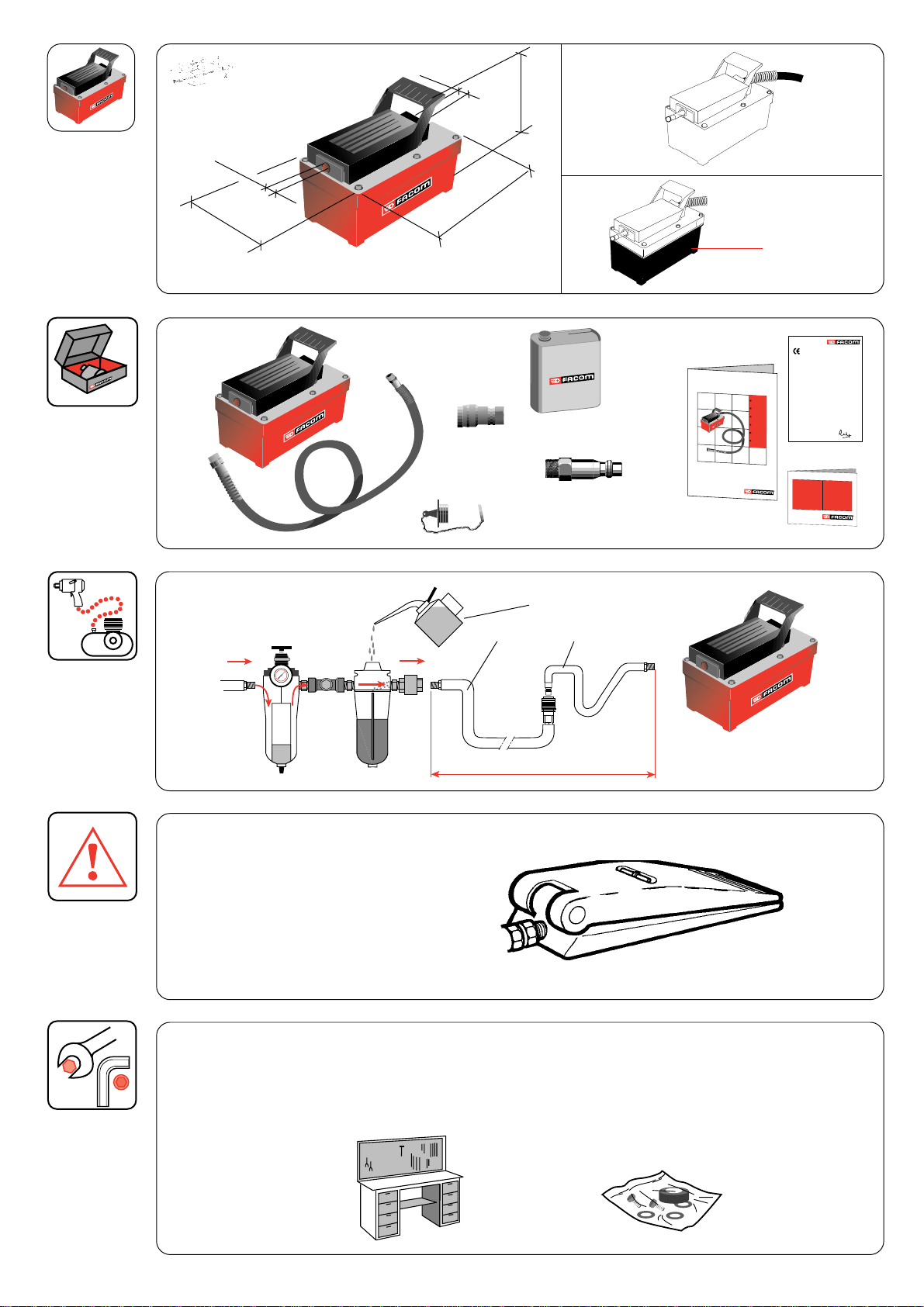
1/4 NPT
126 mm
➡
254 mm
200 mm
3/8 NPT
140 - 280 Nl/mn / 3 - 8 bars
11,70 kg
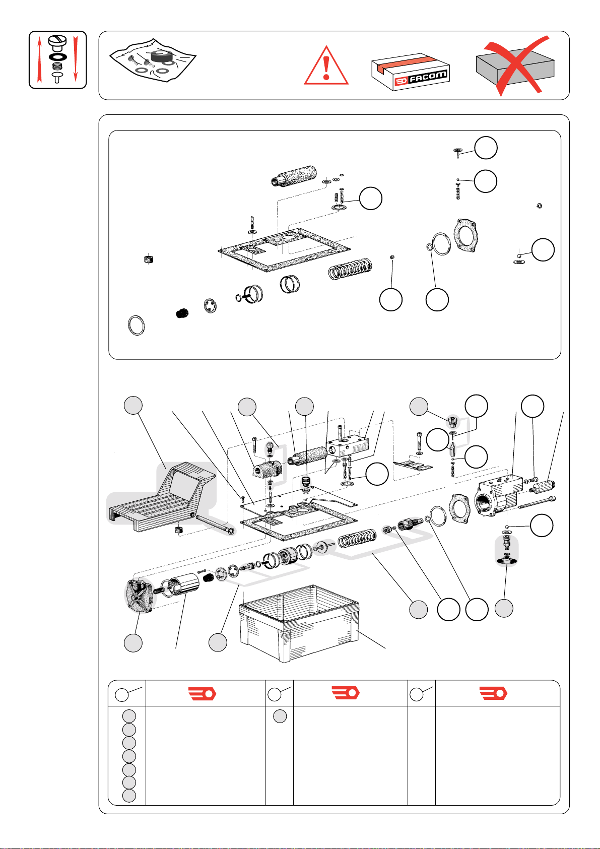
Pour garder la machine en bon état, remplacer les pièces d'usure toutes les 200 heures d'utilisation.
To keep the machine in proper working order, change wear parts afeter 200 hours to use.
Um die Maschine in gutem Zustand zu erhalten, Gebrauchsteile alle 200 Betriebsstunden austauschen.
Om deze machine in goede staat te houden, dienen de aan slitage onderhevige onderdelen na 200 uren gebruik te worken verwisseld.
Para mantener la maquina en buen estado, cambiar las piezas de desgaste despues de 200 horas de utilizacion.
Per mantenere la macchina in buono stato, cambiare le parti d'usura dopo 200 ore di funzionamento.
➠➠
➠➠
WV.1102RN
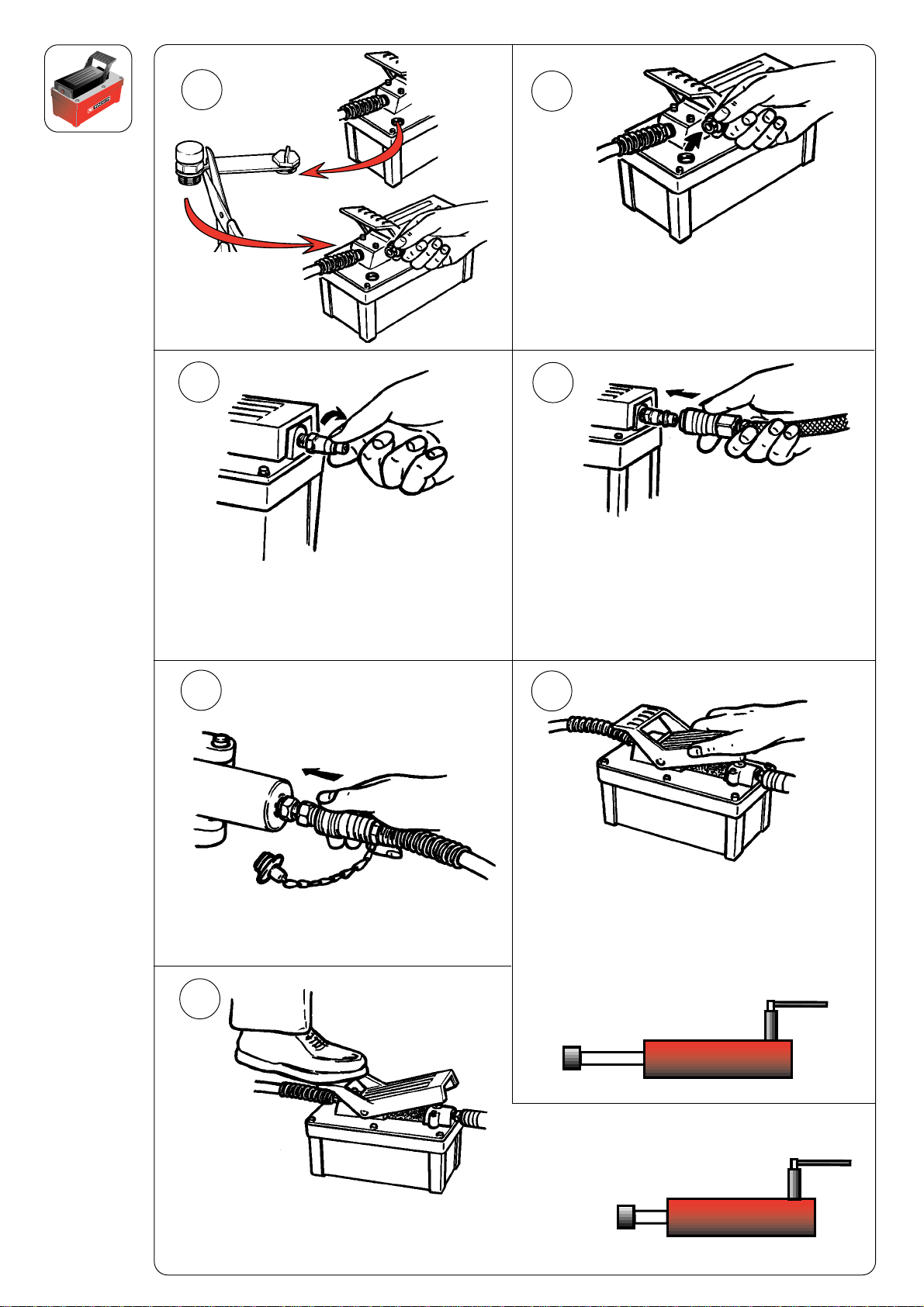
700 bars MAXI
➡
3 - 8 bars
1310 cm3
➡
➡
7 bars
700 bars
10 mètres maxi