Fafl DFD1 User manual

FOCIS
Fiber Optic Connector Inspection System
User’s Guide
www.AFLglobal.com or (800) 321-5298, (603) 528-7780
Test & Inspection


1
Table of Contents
Product Overview ..........................................3
Hardware Overview .........................................4
DFD1 Touchscreen Tablet Controls and Features .......................4
DFD1 Accessories ..............................................6
DFS1 Digital FiberScope .........................................7
Getting Started ............................................7
Connecting AC adapter ..........................................7
Powering up and Shutting down ...................................8
Connecting the DFS1 Digital FiberScope .............................8
Software Overview .........................................9
AFL SimpleView Plus Inspection Software ............................9
Patent-pending Feature - Image Pair Mode . . . . . . . . . . . . . . . . . . . . . . . . . 9
Zoom and Pan ..............................................10
Image Capture, Store, and Recall.................................11
DFD1 Touchscreen Tablet Screen Structure............................11
Operating Modes Summary.....................................12
Image Viewer Summary........................................13
Image Capture and Preview Utilities Field Summary...................14
Operating Instructions.......................................15
Selecting and Changing DFS1 Adapter Tips ...........................15
Inspecting Fibers and Bulkhead Connectors...........................15
Live Image Inspection Mode ......................................16
Image Capture Mode............................................18
Image Manager................................................20

2
Table of Contents
How to Open Images for Review ...................................22
Image Review Mode Summary.....................................23
Settings Mode Summary .........................................24
General Setup .................................................24
Image Capture Setup..........................................25
Text Editor..................................................25
Power Setup ................................................26
About Screen ...............................................27
FAQs .....................................................28
Warranty Terms and Conditions ...............................29
Contact Us: Returning Equipment..............................29
Repair Services.............................................30
Standards Compliance Information.............................30
Safety Information..........................................31

3
Product Overview
The NOYES family of FOCIS integrated ber inspection solutions provides network personnel with the
capability to document ber connector cleanliness. FOCIS combines a palm-sized DFD1 Touchscreen
Tablet, a DFS1 Digital FiberScope and AFL SimpleView Plus inspection software to provide the
inspection and analysis power of current laptop and probe solutions and the ergonomics, ease of use,
ruggedness and ownership costs of basic “live only” viewers. FOCIS solutions are future-proof because
their optical resolution and detection specications exceed current international standards and their
software-based inspection and analysis applications can be upgraded as market requirements evolve.
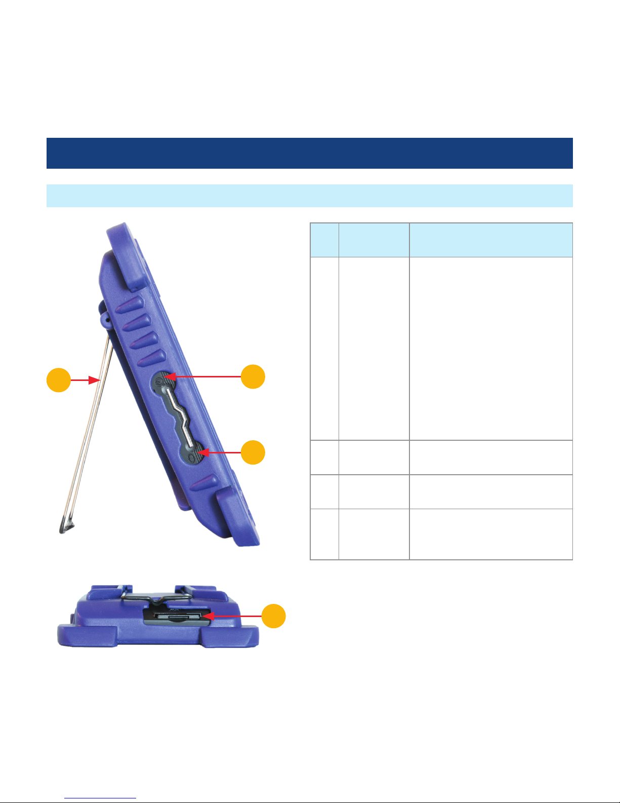
The DFD1 Touchscreen Tablet is a purpose-built, hand-held Windows®computer equipped with AFL
SimpleView Plus inspection software. Its bright, crisp display provides detailed images and its Zoom/
Pan feature allow users to identify the smallest particles, scratches and imperfections. Its portrait
orientation makes it easy to hold and operate with just one hand. Unique to FOCIS is a patent-
pending feature, which simplies before/after, jumper/bulkhead, input/output and other common
ber cleanliness comparisons. Additional features include image capture and store/recall. Up to 1000
ber images may be stored in on-board memory and images may be transferred via any off-the-shelf
USB memory stick or SD ash card. The DFD1 incorporates a proven shock-absorbing rubber boot that
doubles as a tilt stand and hanger.
The DFS1 Digital FiberScope is a high resolution video inspection probe. It is equipped with a focusing
knob and an image capture button. An extensive assortment of DFS1 adapter tips allow it to be used
with all types of ber connector ferrules and bulkhead connectors. Bulkhead tips are available in
multiple lengths as well as straight and 60° angle. Connector adapters are available PC/UPC, APC
polished ferrule in 1.25 mm, 2.5 mm and MTP/MPO connectors.

4
Hardware Overview
DFD1 Touchscreen Tablet Controls and Features
Top View
Front View
Ref Control/
Feature
Description
1Power port This is the interface for the AC
power adapter/charger.
2 Mini USB
function
port
• Allows connection to DFS1
Digital FiberScope for ber
end-face inspection and image
capturing.
• Allows the user to transfer saved
images to a USB memory stick.
3AC adapter/
charger
indicator
When ON, indicates that an AC
adapter is connected to DFD1.
Red light ON indicates that battery
is charging.
• Green light ON indicates that
battery is fully charged.
4Touchscreen
display
Contains on-screen controls and
menus. Used to show live, captured
and saved ber end-face images,
live image settings, image capture
modes, general settings and Image
Manager.
5Boot A proven shock-absorbing rubber
boot.
6Loop This loop can be used as a hanger.
1235
6
5
4

5
Hardware Overview
DFD1 Touchscreen Tablet Controls and Features
Bottom View
Side View
Ref Control/
Feature
Description
1Power
Button
Provides several functions as
follows:
• Press to power up your
DFD1 Touchscreen Tablet.
• Press and hold for less than
7 seconds to enable sleep
mode.
• Press and hold for more
than 7 seconds to fully
shut down your DFD1
Touchscreen Tablet.
2Unused
button
Note: this button has no
function.
3Bail Bail can be used as a tilt stand
or hanger.
4 SD ash
card slot
SD ash card may be used for
storing and transferring ber
end-face images.
3
2
1
4

6
Hardware Overview
DFD1 Controls and Features
Back View
AC Adapter with changeable plugs
DFD1 Accessories
- Cable Retainer
A cable retainer is designed to provide strain relief
for the USB cable.
USB to mini USB converter cable
2- USB to mini USB converter cable is provided
with your DFD1 Touchscreen Tablet. This cable
allows connection of the DFS1 Digital FiberScope
(USB plug) to the DFD1 Touchscreen Tablet (mini
USB port).
AC Adapter
An AC adapter supplied with your DFD1 features
four interchangeable AC adapter plugs for the
following regions: North America, Europe, United
Kingdom, and Asia.
• Choose the appropriate AC adapter plug for
your location and place it into the back of the
AC adapter/charger.
• To change the plug, remove it from the back of
the AC adapter/charger.
• Place another AC adapter plug into position.
1
2
1

7
Hardware Overview
For detailed information on the DFS1 Digital FiberScope and DFS1 Accessories, refer to the DFS1 quick
reference guide provided with your DFS1 or available at www. AFLglobal.com.
DFS1 Digital FiberScope
Getting Started
Connecting AC adapter
The DFD1 Touchscreen Tablet can simultaneously operate and charge the internal battery while
connected to the provided AC adapter. To connect the AC adapter:
• Plug the AC adapter/charger into a standard wall outlet.
• Connect the AC adapter/charger to the power port located on the DFD1 top panel A.
–The AC/Charger indicator Bwill turn on Red if the battery requires charging.
–The AC/Charger indicator turns Green when battery is fully charged.
Top View
A
B

8
Connecting the DFS1 Digital FiberScope
Using the supplied USB to mini USB converter
cable, plug the USB connector of the DFS1 into
the DFD1 USB port A.
Getting Started
Powering up and Shutting down
• Press the Power button Ato power up
your DFD1 Touchscreen Tablet.
• Press and hold the Power button Afor less
than 7 seconds to enable sleep mode.
• Press and hold the Power button Afor at
least 7 seconds to fully shut down your DFD1
Touchscreen Tablet.
Note: The DFD1 Touchscreen Tablet powers
up automatically whenever the AC adapter is
plugged into the power port.
Top View
Side View
A
A

9
Software Overview
AFL SimpleView Plus Inspection Software
Patent-pending Feature - Image Pair Mode
The SimpleView Plus inspection software provides detailed ber end-face images for live ber
inspection, image capture, and image store/recall. Its Zoom and Pan features allow users to identify
the smallest particles, scratches, and imperfections. A unique patent-pending feature, the image pair
mode, simplies before/after, input/output, cleaning, mating and other common ber cleanliness
comparisons. Additional features include image capture and store/recall. Up to 1000 ber images may
be stored in on-board memory and images may be transferred via any off-the-shelf USB memory stick
or SD ash card.
Enabling the Image Pair mode allows the user to select a preset pairing mode prior to bers inspection,
then inspect ber end-faces and save captured images with the selected pairing preset label for
simplied identication, recall, and review.
To use advantages of the Image Pair mode:
1. Select a preset image pairing mode prior to bers inspection.
This setup is done in the Setting mode (see section “Image Capture Setup” on page 25 for
details). The available image pair presets are:
Image Pair Preset Description
Before/after This is a general preset for any before/after ber inspection comparisons
Input/output This is a general preset for any input/output ber inspection comparison
Cleaning This preset is used for inspection ber end-faces before and after cleaning
Mating This preset is used for inspection of mating connector and bulkhead
Documentation This preset is used for as-built/as-found ber installation and maintenance

10
Software Overview
Zoom and Pan
Zoom and Pan features are
available in the Capture Preview
mode (see section “Image Capture
Mode” on page 18 for details)
and the Image Recall/Review
mode (see section “Image Review
Mode Summary” on page 23
for details).
Zooming feature is used to change
the displayed image size within
the Image Viewer. This feature
is useful when the more detailed
view of an image is required.
Panning allows the user to move
around the display area at the
current magnication level.
Image Capture Mode Image Review Mode
Patent-pending Feature - Image Pair Mode
2. After the Image Pair mode is enabled, captured images are stored with the selected pairing mode
label (Before/After, Input/Output, Cleaning, Mating, Documentation) for image pair identication.
3. To simplify images recall and review, stored images may be optionally ltered by the user-selected
image pair mode (see section “Image Manager” on page 20 for details).

11
DFD1 Touchscreen Tablet Screen Structure
The DFD1 Touchscreen Tablet display is divided into
several sections and can be summarized as follows:
AOperating modes and Battery state/
Charger indicator eld - This is where the
user selects one of the DFD1 operating
modes and sees battery charge state or
AC adapter/charger indicator.
See page 12 for details.
BImage Viewer - This is where ber-end
images are displayed.
See page 13 for details.
CImage Capture and Preview utilities
eld - This section contains various setup
utilities and functions.
See page 14 for details.
Software Overview
Image Capture, Store, and Recall
The image capture, store, and recall features enable users to capture and save ber end-face images
for documentation, review, and transfer. DFD1 Touchscreen Tablet is capable to store up to 1000 end-
face images internally. Additionally, images may be saved on SD ash card.
Using any off-the-shelf USB memory stick and the supplied USB to mini USB converter cable or SD ash
card images may be transferred to a PC.
A
B
C

12
Ref Icon Feature/Mode Description
1 Live Image
Mode
This icon represents the Live Image mode. When in any other
mode or screen, tapping this icon will navigate to the Live
Image mode screen.
2Image Manager Tap on this icon to display the Image Manager mode.
3Settings Tapping this icon will select the Settings mode where users
perform General and Capture mode setup, change Power
settings and view the version information in the About screen.
4Battery icon This icon will be displayed when the DFD1 operates on battery
power.
Charge
indicator
This icon will be displayed when the battery is not at 100% and
the AC is attached. Indicates that battery is charging.
Charge
complete
indicator
This icon will be displayed to indicate that the DFD1 operates
from AC and not using the battery. It will be displayed when the
battery has reached a complete charge.
Software Overview
Operating Modes Summary
• Each icon represents a different operating mode
• Tap on a mode icon to select the desired operating mode
A
1 2 3 4
This bar/tab indicates the
currently active mode

13
Software Overview
Image Viewer Summary
B
The Image Viewer occupies the middle
part of the DFD1 screen. It displays one of
the following:
• When DFD1 operates in the Live
Inspection mode, it displays a real-time
image of a fiber end-face that is being
inspected.
• When DFD1 operates in the Image
Capture and Preview mode, it displays a
captured image that is being previewed
before saving.
• When DFD1 operates in the Image
Review mode, it displays a previously
stored image or image pair.

14
Software Overview
Image Capture and Preview Utilities Field Summary
C
Image Capture and Preview Utilities field
provides several functions:
• In the Live Image mode, this field
provides access to the Live Image
Settings mode and provides image
capturing function.
• In the Captured Image Preview mode,
this field allows the user to review the
captured image and either delete or
save it in user-defined folders.

15
Operating Instructions
Inspecting Fibers and Bulkhead Connectors
The following instructions assume the DFS1 Digital FiberScope is congured with the appropriate
adapter tip installed* (see note above), the DFD1 Touchscreen Tablet is powered up, the DFS1 is
connected to the DFD1, and real-time images from the DFS1 are currently being displayed on the DFD1.
1. If testing an optical ber connector:
–Slide the ferrule of the optical ber into the installed adapter probe tip, using caution not to
contaminate the end-face of the ber connector.
–A dark circle will appear on the attached device display.
2. If testing an optical ber connector mounted in a bulkhead adapter:
–Slide the probe adapter tip into the bulkhead adapter.
–Adjust the angle of the adapter tip until a dark circle appears on the attached device display.
3. Rotate the Focus Adjust Knob on the DFS1 clockwise or counter-clockwise until the displayed circle is
in sharp focus.
4. Once a good image has been obtained, it may be captured pressing the Display Capture button on
the DFS1, or by tapping the Capture icon on the DFD1 Touchscreen Tablet.
–Either of these actions results in the DFD1 freezing the displayed live image and present it as a still
image in the Image Capture mode.
5. In the Capture mode, review the captured image using Pan and Zoom features.
6. If satised with the displayed image, tap Save to store; otherwise, press Delete (refer to section titled
“Image Capture Mode” on page 18).
7. After either saving or deleting the captured image, the DFD1 reverts to the Live Image mode.
*For information on how to select and change DFS1 adapter tips, refer to the DFS1 Digital FiberScope
Quick Reference Guide supplied with your DFS1 and available at www.AFLglobal.com
Selecting and Changing DFS1 Adapter Tips

16
Operating Instructions
Live Image Inspection Mode
The Live Image mode displays real-time images of the ber end-face that is being inspected with the
DFS1 Digital FiberScope.
5
4
2
1
3
This label is
displayed to
indicate that DFD1
operates in the
Live Image mode.
This bar/tab
indicates that DFD1
operates in the Live
Image or Captured
mode.
This field displays
the Image pair
mode setup that
are user-defined
in the Settings
mode, which can be
accessed by tapping
the Settings
icon A.
A

17
Live Image Inspection Mode
Operating Instructions
Ref Icon Feature/Mode Description
1Operating
modes
For details, see section titled “Operating Modes Summary”
on page 12.
2Image Viewer This eld displays a real-time image of a ber end-face that
is being inspected.
3Live Image
Settings
While in the Live Image mode, tapping on this icon will
display the Settings screen and allow the user to choose Live
Image Brightness, Contrast and Color settings.
Tap to exit
4Image Capture Tapping the Capture icon will freeze the displayed live image
and switch to the Capture mode, where the captured image
can be analyzed and saved or deleted.
5File Number This eld displays the current le number, which may be
changed by tapping the Up or Down arrow. Note: Once the
image has been saved in the Capture mode screen, the le
number is automatically incremented.

18
Operating Instructions
Image Capture Mode
The Image Capture mode displays a still image of the ber being inspected. This mode allows the user
to preview the captured images, change the currently displayed le number and either store or delete
the displayed image. The Capture mode is accessed from the Live Image mode when the Capture icon
is pressed.
56
7
1
3
2
For details, see
section titled
“Operating Modes
Summary” on
page 12.
This field displays the
Image pair mode setup
that are user-defined
in the Settings mode,
which can be accessed
by tapping the
Settings icon A.
A
This manual suits for next models
1
Table of contents