fafnir ME 6 Series Guide

Technical Documentation
FAFNIR GmbH • Schnackenburgallee 149 c • 22525 Hamburg • Tel.: +49 / 40 / 39 82 07–0 • Fax: +49 / 40 / 390 63 39
ME 6 …
Overfill prevention sensor tester
Version: 4
Edition:
2019-04
Art. no.: 350227

I Contents
Table of contents
1Overview .................................................................................................... 1
2Safety instructions .................................................................................... 2
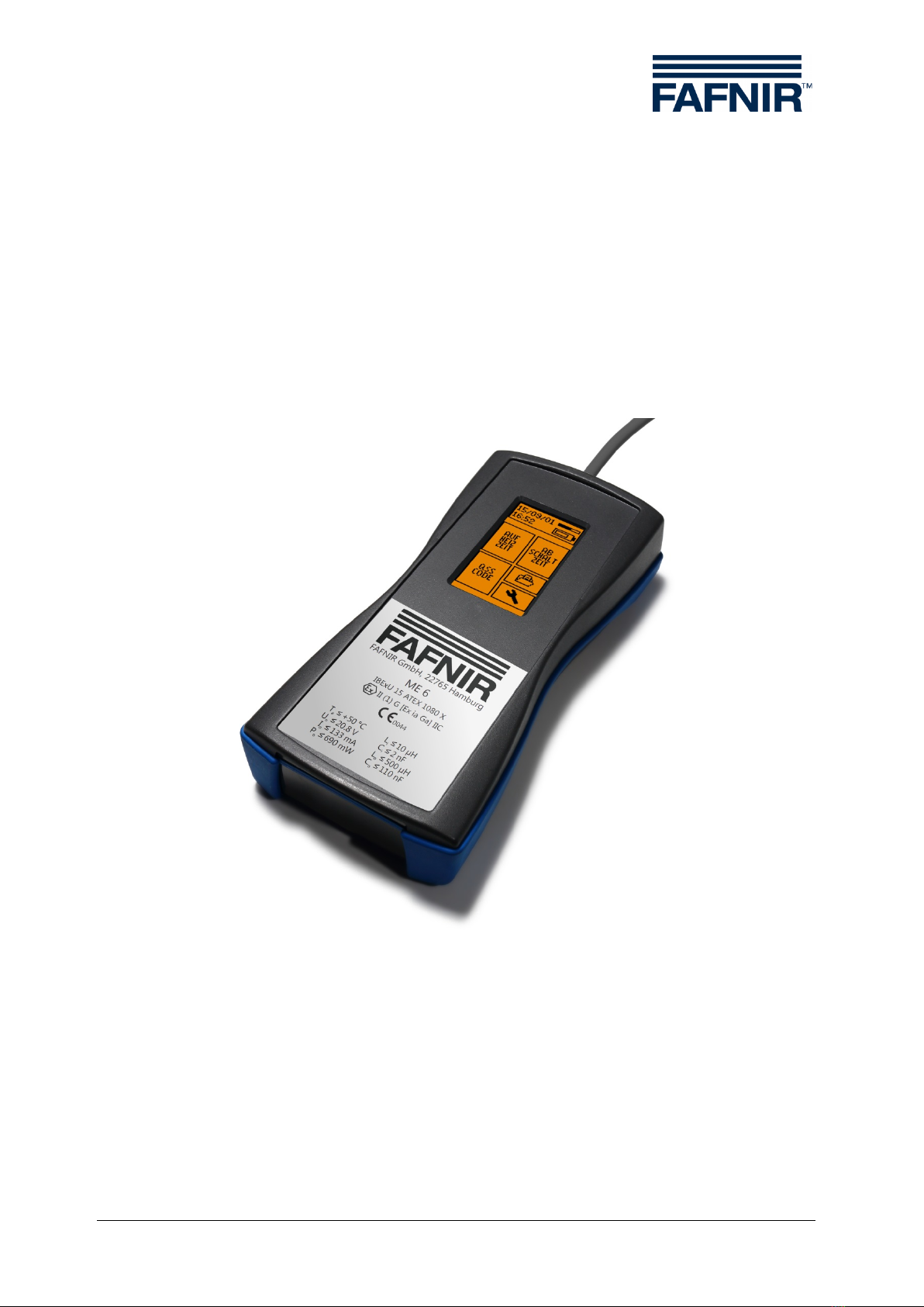
3The ME 6 ... overfill prevention sensor testing device ......................... 3
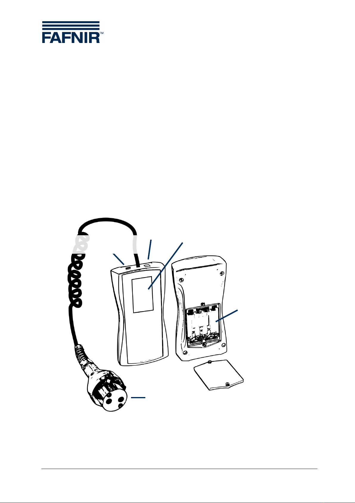
3.1 Design and construction .................................................................................................................3
3.2 Function .................................................................................................................................................4
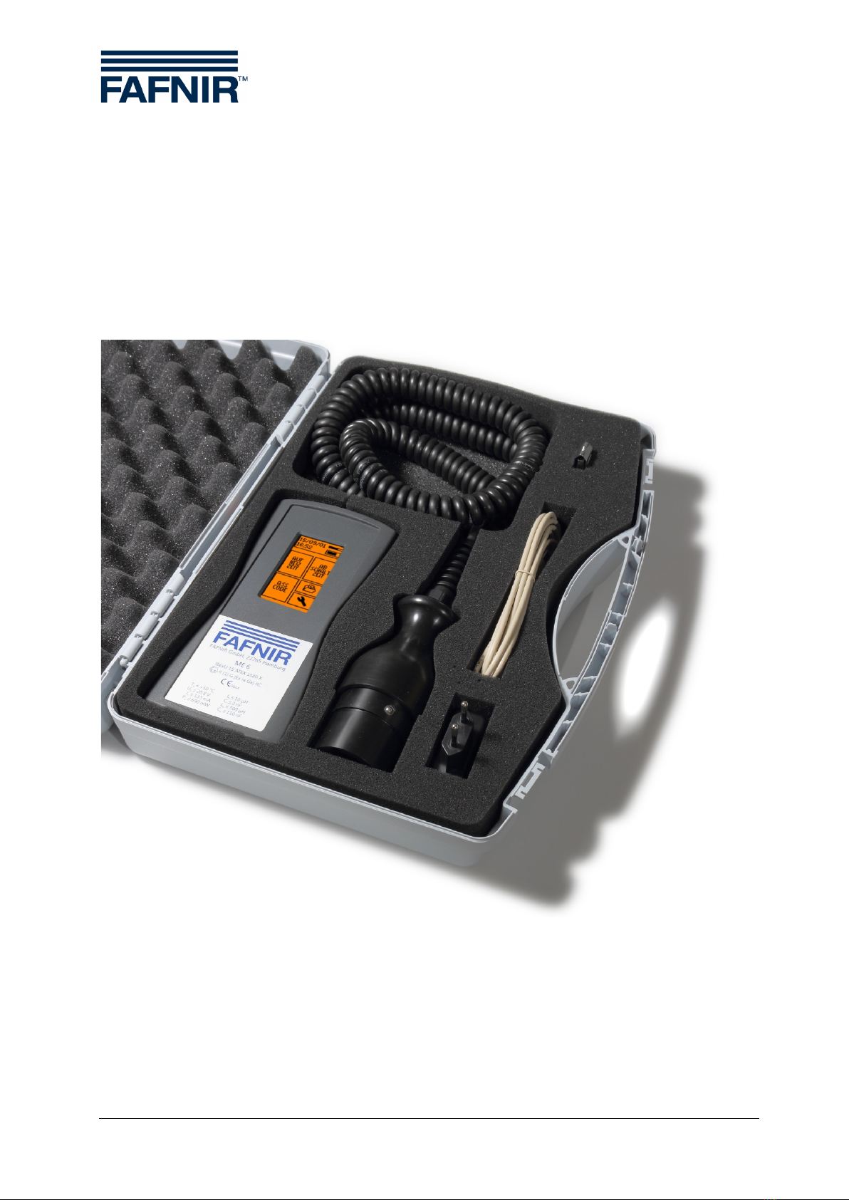
3.3 Scope of delivery................................................................................................................................5
4Operation ................................................................................................... 6
4.1 Fundamentals ......................................................................................................................................6
4.2 Start-Up .................................................................................................................................................8
4.2.1 Basic settings .......................................................................................................................................9
4.3 Testing the Overfill Prevention Sensor.....................................................................................11
4.3.1 Heating-up time ...............................................................................................................................13
4.3.2 Switch-off time..................................................................................................................................13
4.3.3 QSS Code (ME 6 P) ..........................................................................................................................15
4.4 Power saving (stand-by) mode and reactivation..................................................................15
4.5 Settings ................................................................................................................................................16
4.5.1 Country selection .............................................................................................................................17
4.5.2 Date and time....................................................................................................................................17
4.5.3 Backlight ..............................................................................................................................................18
4.5.4 Touch screen calibration................................................................................................................18
4.5.5 QSS code identifiers........................................................................................................................20
4.5.6 Readings archive...............................................................................................................................21
4.5.7 Delete readings.................................................................................................................................21
4.5.8 Resetting to factory settings........................................................................................................22
4.6 Power supply......................................................................................................................................22
4.6.1 Changing the rechargeable batteries .......................................................................................22
4.6.2 Regular charging of the rechargeable batteries necessary ..............................................23
5PC software..............................................................................................24
5.1 Driver installation .............................................................................................................................24
5.2 Starting the ME 6 Software...........................................................................................................24
5.2.1 Settings ................................................................................................................................................24
5.2.2 Records ................................................................................................................................................26

Contents II
6Technical Data .........................................................................................27
7List of figures...........................................................................................28
8List of tables.............................................................................................28
9Annex........................................................................................................29
9.1 EC Declaration of Conformity......................................................................................................29
9.2 EC Type Examination Certificate (ATEX) ..................................................................................30
9.3 Instructions.........................................................................................................................................32
© Copyright:
Reproduction and translation are permitted only with the written consent of FAFNIR GmbH. FAFNIR
GmbH reserves the right to carry out product alterations without prior notice.

Page 1/33 Design and construction
1Overview
Testing obligations in accordance with §§ 15 and 16 of the German Indus-
trial Safety Regulations (BetrSichV) and § 1 of the German Regulations on
Equipment Handling Substances Hazardous to Water (WasgefStAnlV). In
other countries, the corresponding national rules and regulations must be
observed.
When in operation, storage facilities for static tanks, filler points, petrol sta-
tions, airport refuelling equipment, and their components, e.g. overfill
prevention sensors, must be tested by an approved inspection agency prior
to commissioning, re-commissioning (after modifications subject to testing)
as well as repeatedly at specific testing intervals.
The system parts, e.g. overfill prevention sensors, must be tested by the op-
erator or an authorised person as required by the manufacturer's operating
instructions at regular intervals.
The ME 6 … overfill prevention sensor testing device guarantees optimal and safe test-
ing in accordance with prEN 13616-2 …
Three different types of these testing devices are available; they differ in the nature of
the application and the medium which is to be monitored:
•The ME 6 is used to test overfill prevention sensors without product coding.
•The ME 6 P is used to test overfill prevention sensors with product coding
in accordance with Quality Assurance systems (QSS).
•The ME 6 F is used to test overfill prevention sensors in LPG tanks.
In the following sections you will be guided by means of a detailed description
through the installation and commissioning of the ME 6 … overfill prevention sensor
testing device.
The ME 6 … overfill prevention sensor testing device may only be supplied
with power by 4 pcs NiMH rechargeable batteries (type AA 1.2 V, 2000 mAh).

Design and construction Page 2/33
2Safety instructions
The safety instructions in this manual are marked as follows:
If you do not comply with the safety instructions, there is a risk of accident,
or the device/system may be damaged.
Useful tips and information in this manual that should be observed appear
in italics and are identified by this symbol.
The ME 6 … overfill prevention sensor testing device is used to test overfill prevention
sensors in storage tanks. The testing device must be used exclusively for this purpose.
The manufacturer accepts no liability for any form of damage resulting from improper
use.
The ME 6 … overfill prevention sensor testing device has been developed, manufac-
tured and tested in accordance with the latest good engineering practices and
generally accepted safety standards. Nevertheless, hazards may arise from its use. For
this reason, the following safety instructions must be observed:
Do not change or modify the testing device or add any equipment without
the prior consent of the manufacturer.
The operation and maintenance of the testing device must be carried out
by expert personnel only. Specialised knowledge must be acquired by regu-
lar training.
Operators, installers and service technicians must observe all applicable
safety regulations. This also applies to any local safety and accident pre-
vention regulations which are not stated in this manual.
The manufacturer accepts no liability for any other batteries than the
required NiMH rechargeable batteries, see chapter 6, Technical Data.
Charging standard batteries instead of rechargeable batteries result in the
risk of fire or explosion.

Page 3/33 Design and construction
3The ME 6 ... overfill prevention sensor testing device
3.1 Design and construction
The ME 6 ... overfill prevention sensor testing device is used to test overfill prevention
sensors in accordance with prEN 13616-2. In order to do this, the testing device is
equipped with a socket coupler on a flexible spiral cable.
The testing device is operated by a touch screen.
Readings which has been saved can be transferred to a PC/laptop and archived by
means of software and the USB socket.
The testing device is powered by 4 pcs NiMH rechargeable batteries. These can be
replaced by the user. The batteries can be charged by a plug-in power supply or a
PC/lap top via the USB socket.
A toggle switch is used to move between the two operating modes Measurement and
USB connection/charging.
Figure 1: The ME 6 ... overfill prevention sensor testing device
USB socket
Type B
Battery compartment
Overfill prevention sensor coupling socket
Toggle switch
Measurement / USB
Touchscreen

Function Page 4/33
3.2 Function
The overfill prevention sensor is heated by the intrinsically safe electric current of the
ME 6 ... overfill prevention sensor testing device. The heating-up time needed is meas-
ured, assessed and presented on the screen. The switch-off time is treated in the same
way. The QSS coding is captured and also displayed (ME 6 P).
As the testing device has an intrinsically safe output circuit, it can be used for testing
all overfill prevention sensors approved by prEN 13616-2. The testing device itself must
be operated outside the Ex area. The type 903 socket coupler needed for the connec-
tion to the overfill prevention sensor is equipped with an appropriate length of cable.
The testing device must be equipped with a FAFNIR socket coupler type AS 903 for
checking the product identification.
The testing device is fitted with 4 pcs. NiMH rechargeable batteries. These batteries are
charged with the plug-in power supply via the USB socket or with the USB host of a
PC/laptop. They can only be charged when in USB mode. Depending on the nominal
capacity of the batteries, it takes about 10 hours to charge them. The batteries can be
freely exchanged.

Page 5/33 Scope of delivery
3.3 Scope of delivery
•The ME 6 ... overfill prevention sensor testing device with connected coupling
cable (with product identification, without product identification, or LPG)
•USB cable type A/B
•4 pcs NiMH rechargeable batteries (type AA 1.2 V, 2000 mAh), plugged in
or separate
•Technical Documentation
Figure 2: Scope of delivery in carrying case as a set (e.g. ME 6 P)

Fundamentals Page 6/33
4Operation
4.1 Fundamentals
The ME 6 ... overfill prevention sensor testing device is operated by a Touchscreen;
operations are activated by touching special activation fields. The user is generally
guided by icons or informative items of short text with the result that it is quite evident
in the individual screens which functions are triggered by the various activation fields.
The activation fields which regularly recur are listed below.
Confirmation, Activity successful, Amendments accepted
Refusal, Unsuccessful, Abort without amendments, Delete
Return to the previous screen
Input of figures
Figure 3: Activation fields of the graphical user guidance
In this manual important activation fields are highlighted by a fingertip in symbolic
form.
Excessive pressure can damage the screen. Gently touching the screen is
sufficient to operate it.
If no reaction is produced, the touch screen is perhaps decalibrated. In this
case, all that is needed to start the calibration process is to touch the screen
with a finger for about 5 seconds.

Page 7/33 Fundamentals
When in the main screens, the date, time, memory occupancy, and battery status is
indicated in the upper line of the screen.
<Measuring range data storage over 50% full
<Batteries about 1/3 discharged
<Memory almost empty
<Batteries being charged
<Memory almost full
<No batteries inserted; testing device being powered via the
USB socket
Figure 4: Status display

Start-Up Page 8/33
4.2 Start-Up
If the testing device was supplied with 4 unplugged separate NiMH rechargeable bat-
teries, first the batteries must correctly be inserted for starting up. Open the battery
compartment on the rear side of the testing device with a Philips screwdriver and in-
sert the batteries according to the symbols in the battery compartment. The testing
device starts for the first time to enter the basic settings.
Figure 5: Battery compartment in the rear side of the testing
device
Before starting up the testing device, the rechargeable batteries must first be
charged. A complete charging takes about 10 hours.

Page 9/33 Start-Up
4.2.1 Basic settings
After the first start or reset to the factory settings, the basic settings are to be set dis-
played automatically in sequence. The touch screen must then be calibrated. To do
this, each of the icons in the 4 corners must be touched until the next one is shown. A
point situated in the middle must be touched as final test.
a)
b)
c)
Figure 6: Calibrating the touch screen
The calibration can fail if the points are incorrectly touched. In this case the basic set-
tings are interrupted and the standard values are loaded. However, it is still possible to
configure the testing device at a later time by means of the graphical user interface.
a)
b)
Figure 7: Results of touch screen calibration
a) Successful b) Unsuccessful

Start-Up Page 10/33
The country is selected after calibrating the touch screen. This determines the user
interface language and, when applicable, the assessment methods. Select by touching
the relevant field.
Figure 8: Country selection
The real time clock is adjusted after selecting the country.
The date can be set in the first screen and the time in hours and minutes in the second
screen by touching + and – .
a)
b)
c)
Figure 9: Date and time b) Setting the date c) Setting the time

Page 11/33 Testing the Overfill Prevention Sensor
4.3 Testing the Overfill Prevention Sensor
The operating mode Measurement must be set in order to be able to test overfill pre-
vention sensors with the ME 6 ... overfill prevention sensor testing device. To set the
mode, push the toggle switch on the upper side of the testing device into the corre-
sponding position.
Figure 10: Toggle switch in the measuring position
Testing the heating-up time of an overfill prevention sensor starts as soon as an overfill
prevention sensor is connected to the socket coupler and recognised by the system.
If the test fails to start, the resistance is outside the applicable figures; this
is caused, for example, by a short circuit or a cable breakage or by the tog-
gle switch being in the wrong position.
The standard test includes the test of the heating-up time and optionally after success-
ful completion the test of the switch-off time. This can be declined in a selection
dialogue. For ME 6 P the standard test includes the product recognition (QSS code).
These tests can also be carried out individually if they are selected via
the main menu in the operating mode “Measurement “.
Figure 11: Main menu, operating mode "Measurement"

Testing the Overfill Prevention Sensor Page 12/33
The faults SHORT CIRCUIT and RESISTANCE TOO HIGH can occur in all tests, which
stop the test immediately. In the case of the RESISTANCE TOO HIGH fault, the testing
device has perhaps not been switched to the Measurement mode with the result that
the overfill prevention sensor is not connected to the heating circuit. Or a cable is
broken.
Figure 12: Fault display "Short circuit" and "Resistance too high"

Page 13/33 Testing the Overfill Prevention Sensor
4.3.1 Heating-up time
The test starts automatically when the overfill prevention sensor is connected to the
socket coupler or if the field HEATING-UP TIME is selected in the main menu.
For ME 6 P the testing device attempts to read the QSS code. The code is displayed
and the actual measurement commences. The overfill prevention sensor is heated up
and the progress of the change in resistance is displayed graphically. If the target re-
sistance value is not reached within 180 seconds, the measurement is aborted with a
fault. At the end of a successful test, a dialogue asks if the TEST FOR SWITCH-OFF TIME
is to be performed.
a)
b)
c)
Figure 13:
Test for heating-up time
b) Error message c)
Test result
4.3.2 Switch-off time
The TEST FOR SWITCH-OFF TIME can be performed as an option immediately after a
successful TEST FOR HEATING-UP TIME. A corresponding dialogue is superimposed on
the display for this purpose. The test can also be selected manually by selecting the
field SWITCH-OFF TIME in the main menu.
The switch-off time is tested by heating the overfill prevention sensor. This is displayed
by the message HEAT. After a target temperature has been reached, the message
changes to READY and a 2-second count-down is displayed which ends with the com-
mand IMMERSE. The overfill prevention sensor must now be manually immersed in a
test liquid. The time needed for the overfill prevention sensor to fall to a pre-set value
is measured.

Testing the Overfill Prevention Sensor Page 14/33
Figure 14: Images showing the test of the switch-off time
from the heating-up phase to the "Immerse" command after the count-down
Figure 15: Images relating to the immersion of the overfill prevention sensor
with possible measuring results

Page 15/33 Power saving (stand-by) mode and reactivation
4.3.3 QSS Code (ME 6 P)
This test is carried out at the same time as the TEST FOR HEATING-UP TIME is per-
formed. The test can also be started manually by selecting the field QSS CODE in the
main menu.
Figure 16: Checking the QSS code (ME 6 P)
4.4 Power saving (stand-by) mode and reactivation
If not connected to a USB power supply, the testing device switches to a stand-by
mode after 30 seconds of inactivity. The screen is switched off in this mode. The testing
device can be reactivated by touching the screen for about 2 seconds or connecting an
overfill prevention sensor. It is therefore also possible to take a measurement directly
after the stand-by mode.

Settings Page 16/33
4.5 Settings
The settings of the ME 6 ... overfill prevention sensor testing device can be adjusted
using the ME 6 PC software when in USB operating mode (see Section 5 PC software)
or directly on the testing device. In USB operating mode, the settings can be accessed
directly via the main menu; when in Measurement mode, the spanner (wrench) icon
must be selected.
a)
in USB mode
b)
in measuring mode
settings
Figure 17: Settings
Device information
Select language / country code
Set date and time
Set screen brightness
Calibrate touch screen
Edit QSS code identifiers
Display saved data
Delete saved data
Reset to factory settings
Figure 18: Symbols of settings

Page 17/33 Settings
4.5.1 Country selection
Country selection determines the user interface language and, when applicable, the
assessment methods. Selection is by touching the relevant field.
Figure 19: Country selection
4.5.2 Date and time
The date can be set by touching +and -in the first screen. The time can be set in
hours and minutes in the second screen. The Xbutton aborts the process; the current
date is not changed.
a)
b)
Figure 20: Setting the date and time
This manual suits for next models
3
Table of contents
Other fafnir Test Equipment manuals
Popular Test Equipment manuals by other brands

Radio Shack
Radio Shack Micronta 22-204 A operating instructions

PCE Health and Fitness
PCE Health and Fitness PCE-HT 224E Operation manual

ATD Tools
ATD Tools ATD8601 instruction manual

Tektronix
Tektronix 556 instruction manual

Oakton
Oakton EcoTestr CTS1 operating manual

GW Instek
GW Instek GDS-3152 user manual