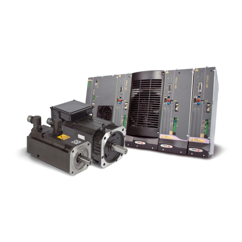
Fagor BCSD Series User manual

SYSTEM BCSD
User manual
Ref. 1809

All rights reserved. No part of this documentation may be transmitted,
transcribed, stored in a backup device or translated into another language
without Fagor Automation’s consent. Unauthorized copying or distributing of this
software is prohibited.
The information described in this manual may be subject to changes due to
technical modifications. Fagor Automation reserves the right to change the
contents of this manual without prior notice.
All the trade marks appearing in the manual belong to the corresponding owners.
The use of these marks by third parties for their own purpose could violate the
rights of the owners.
It is possible that CNC can execute more functions than those described in its
associated documentation; however, Fagor Automation does not guarantee the
validity of those applications. Therefore, except under the express permission
from Fagor Automation, any CNC application that is not described in the
documentation must be considered as “impossible”. In any case, Fagor
Automation shall not be held responsible for any personal injuries or physical
damage caused or suffered by the CNC if it is used in any way other than as
explained in the related documentation.
The content of this manual and its validity for the product described here has been
verified. Even so, involuntary errors are possible, hence no absolute match is
guaranteed. However, the contents of this document are regularly checked and
updated implementing the necessary corrections in a later edition. We appreciate
your suggestions for improvement.
The examples described in this manual are for learning purposes. Before using
them in industrial applications, they must be properly adapted making sure that
the safety regulations are fully met.

FAGOR AUTOMATION S.COOP.
Brushless AC
Servo Drives
~ BCSD series ~
Ref. 1809

BCSD-4/116 Digital Brushless S ervo Drive system - Ref. 1809
About this manual
This manual describes the following information required for designing and maintaining BCSD series
servodrives.
• Specification of the servodrives and servomotors.
• Procedures for installing the servodrives and servomotors.
• Procedures for wiring the servodrives and servomotors.
• Procedures for operation of the servodrives.
• Procedures for using the panel operator.
• Communication protocols.
• Ratings and characteristics.
Intended Audience:
• Those designing BCSD series servodrive systems.
• Those installing or wiring BCSD series servodrives.
• Those performing trial operation or adjustments of BCSD series servodrives.
• Those maintaining or inspecting BCSD series servodrives.
All rights reserved. No part of this publication may be reproduced, stored in a retrieval system, or
transmitted, in any form, or by any means, mechanical, electronic, photocopying, recording, or otherwise,
without the prior written permission of FAGOR. No patent liability is assumed with respect to the use of
the information contained herein.

Digital Brushless AC Servo Drive system - Ref. 1809 BCSD-5/116
Safety Precautions
• Do not connect the servomotor directly to the local electrical network.
Failure to observe this may result in damage to servomotor.
• Do not plug or unplug connectors from servodrive after power is on.
Failure to observe this may result in damage to servodrive and servomotor.
• Note that residual voltage still remains in the servodrive even after the power is turned off.
Please be noted that even after the power is turned off, residual voltage still remains in the capacitor
inside the servodrive. If inspection is to be performed after the power is turned off, always wait at least
5 minutes to avoid the risk of an electrical shock.
• Keep servodrives and other devices separated by at least 10 mm.
The servodrive generates heat. Install the servodrive so that it can radiate heat freely. When installing
servodrives with other devices in a control panel, provide at least 10 mm space between them and
50 mm space above and below them. Please install servodrives in an environment free from conden-
sation, vibration and shock.
• Perform noise reduction and grounding properly.
Please comply with the following instructions strictly to avoid the noisy generated by signal lines.
1. Separate high-voltage cables from low-voltage cables.
2. Use cables as short as possible.
3. Single point grounding is required for the servomotor and servodrive (grounding resistance 100
or below).
4. Never use a line filter for the power supply in the circuit.
• Conduct a voltage resistance test for the servodrive under the following conditions:
1. Input voltage: AC 1500 Vrms, 1 minute
2. Braking current: 100 mA
3. Frequency: 50/60 Hz
4. Voltage applied point: Between L1, L2, L3 terminals and frame ground.
• Use a fast-response type ground-fault interrupter.
For a ground-fault interrupter, always use a fast-response type or one designed for PWM inverters.
Do not use a time-delay type.
• Do not make any extreme adjustments or setting changes of parameters.
Failure to observe this caution may result in injury or damage to the product due to unstable operation.
• The servomotor cannot be operated by turning the power on and off.
Frequently turning the power ON and OFF causes the internal circuit elements to deteriorate, resulting
in unexpected problems. Always start or stop the servomotor by using reference pulses.

BCSD-6/116 Digital Brushless S ervo Drive system - Ref. 1809
Revision History
Date Revised Content Remark
2014-02
1. Remove 200V drives and motors BCSD-15AMA, BCSD-20AMA,
BCSD-30AMA, BCSD-50AMA, FBM-10ADA, FBM-15ADA, FBM-
20ADA, FBM-30ADA, FBM-50ADA.
2. Add 400V drives and motors BCSD-10DMA, BCSD-15DMA, BCSD-
20DMA, BCSD-30DMA, BCSD-50DMA, FBM-10DDA, FBM-
15DDA, FBM-20DDA, FBM-30DDA, FBM-50DDA.
2014-10
1. Change FBS-08ADA and FBS-10ADA motors to FBS-08ADB and
FBS-10ADB.
2. Change BSC-CS-XX and BSC-CA-XX cables to BSC-CS-XX-01 and
BSC-CA-XX-01.
2015-03 1. Dimension of FBS and FBM motors.
2015-06 1. All motors use absolute encoder.
2. Add alarm A25, A26, A27.
2016-01 1. Remove cable BSC-CA-XX-01, change to BSC-CA-XX-02.
2017-11
1. New driver software version, BCSD-XXXMA-01.
2. New motors, FBM-10/15/20DDB.
3. New power cable MPC-FBM-14-XX-01 and new feedback cable
EEC-FBM-A-XX-01 used for above new motors (because power
connector and feedback connector on new motors are different from
previous one).
4. Power cable and feedback cable add 20 m length specification.
5. Remove communication cable BSC-PC, change to BSC-PC-USB.

Digital Brushless AC Servo Drive system - Ref. 1809 BCSD-7/116
1. PRODUCTS GENERAL DESCRIPTION............................................................................................ 9
1.1. Servo motor .............................................................................................................................. 10
1.1.1. FBS Servomotor ............................................................................................................... 10
1.1.2. FBM Servomotor............................................................................................................... 14
1.1.3. FBS/FBM motor appearance and part name.................................................................... 20
1.2. BCSD Servodrive...................................................................................................................... 21
1.2.1. BCSD drive General information ...................................................................................... 21
1.2.2. BCSD drive Specifications and Models ............................................................................ 26
1.2.3. BCSD drive Dimensional Drawings .................................................................................. 28
1.3. Encoder and Power cables....................................................................................................... 30
1.4. Communication cables.............................................................................................................. 31
2. INSTALLATION................................................................................................................................ 32
2.1. Servomotor ............................................................................................................................... 32
2.1.1. Storage ............................................................................................................................. 32
2.1.2. Installation Sites................................................................................................................ 32
2.1.3. Installation Alignment........................................................................................................ 33
2.1.4. Installation Orientation ...................................................................................................... 33
2.1.5. Handling Oil and Water..................................................................................................... 33
2.1.6. Cable Tension................................................................................................................... 33
2.2. Servodrive................................................................................................................................. 34
2.2.1. Storage ............................................................................................................................. 34
2.2.2. Installation Sites................................................................................................................ 34
2.2.3. Installation Orientation ...................................................................................................... 34
2.2.4. Installation Method............................................................................................................ 35
3. WIRING............................................................................................................................................. 36
3.1. Main Circuit Wiring.................................................................................................................... 36
3.1.1. Names and Functions of Main Circuit Terminals .............................................................. 36
3.1.2. Typical Main Circuit Wiring Examples .............................................................................. 37
3.2. I/O Signals ................................................................................................................................ 39
3.2.1. Example of I/O Signal Connections .................................................................................. 39
3.2.2. I/O Signal Names and Functions ...................................................................................... 40
3.2.3. I/O Signal Connector (CN1) Terminal Layout ................................................................... 41
3.2.4. Interface Circuit................................................................................................................. 42
3.3. Wiring Encoders........................................................................................................................ 43
3.3.1. Connecting an Encoder (CN2).......................................................................................... 43
3.3.2. Encoder Connector (CN2) Terminal Layout ..................................................................... 43
3.4. Communication Connection...................................................................................................... 44
3.4.1. Communication Connector (CN3) Terminal Layout.......................................................... 44
3.4.2. Communication Connector (CN4) Terminal Layout.......................................................... 44
3.5. Wiring Examples ....................................................................................................................... 45
3.5.1. CAN Control Mode............................................................................................................ 45
4. OPERATION..................................................................................................................................... 46
4.1. Trial Operation .......................................................................................................................... 46
4.1.1. Trial Operation for Servomotor Without Load ................................................................... 48
4.1.2. Trial Operation for Servomotor without Load from Host Reference.................................. 50
4.1.3. Trial Operation with the Servomotor Connected to the Machine ...................................... 53
4.1.4. Trial Operation for Servomotor with Brakes...................................................................... 54
4.2. Control Mode Selection............................................................................................................. 55
4.3. Setting Common Basic Functions.............................................................................................56
4.3.1. Setting the Servo ON Signal............................................................................................. 56
4.3.2. Switching the Servomotor Rotation Direction ................................................................... 57
4.3.3. Setting the Overtravel Limit Function................................................................................ 58
4.3.4. Setting for Holding Brakes ................................................................................................ 60
4.3.5. Instantaneous Power Loss Settings ................................................................................. 63

BCSD-8/116 Digital Brushless AC Servo Drive system - Ref. 1809
4.4. Operating Using Speed Control ................................................................................................ 64
4.4.1. Setting Parameters ........................................................................................................... 64
4.4.2. Setting Input Signals......................................................................................................... 64
4.4.3. Adjusting Reference Offset...............................................................................................65
4.4.4. Soft Start........................................................................................................................... 65
4.4.5. Speed Reference Filter Time Constant ............................................................................ 66
4.4.6. S-curve Risetime .............................................................................................................. 66
4.4.7. Encoder Signal Output...................................................................................................... 67
4.5. Other Output Signals ................................................................................................................ 69
4.5.1. Servo alarm output ........................................................................................................... 69
4.5.2. Servo Ready (/S-RDY) Output.......................................................................................... 70
4.6. Online Autotuning ..................................................................................................................... 71
4.6.1. Online Autotuning ............................................................................................................. 71
4.6.2. Online Autotuning Procedure............................................................................................ 72
4.6.3. Setting Online Autotuning ................................................................................................. 73
4.6.4. Machine Rigidity Setting for Online Autotuning ................................................................ 73
4.7. Absolute Encoders.................................................................................................................... 74
4.7.1. Selecting an Absolute Encoder......................................................................................... 74
4.7.2. Handling Battery ............................................................................................................... 75
4.7.3. Replacing Battery ............................................................................................................. 76
4.7.4. Absolute Encoder Setup(Fn010, Fn011) .......................................................................... 76
4.8. Friction compensation............................................................................................................... 77
4.8.1. Related parameters .......................................................................................................... 77
4.8.2. How to set Pn206 – Pn211 ............................................................................................... 78
5. Panel Operator ................................................................................................................................ 79
5.1. Basic Operation ........................................................................................................................ 79
5.1.1. Functions on Panel Operator............................................................................................ 79
5.1.2. Resetting Servo Alarms .................................................................................................... 79
5.1.3. Basic Mode Selection ....................................................................................................... 80
5.1.4. Status Display Mode......................................................................................................... 80
5.1.5. Operation in Parameter Setting Mode .............................................................................. 82
5.1.6. Operation in Monitor Mode ............................................................................................... 83
5.2. Operation in Utility Function Mode............................................................................................ 85
5.2.1. Alarm Traceback Data Display ......................................................................................... 86
5.2.2. Parameter Settings Initialization ....................................................................................... 86
5.2.3. Operation in JOG Mode....................................................................................................87
5.2.4. Automatic Adjustment of the Speed Reference Offset ..................................................... 88
5.2.5. Manual Adjustment of the Speed Reference Offset ......................................................... 89
5.2.6. Offset-adjustment of Servomotor Current Detection Signal.............................................. 90
5.2.7. Software Version Display.................................................................................................. 92
5.2.8. Static Inertia Detection...................................................................................................... 92
5.2.9. Absolute Encoder Multiturn Data and Alarm Reset .......................................................... 93
5.2.10. Absolute Encoder Related Alarms Reset ....................................................................... 93
6. CAN COMMUNICATION.................................................................................................................. 94
6.1. CAN Communication Wiring ..................................................................................................... 94
6.2. CAN Communication Related Parameters ............................................................................... 94
7. WinBCSD SOFTWARE.................................................................................................................... 95
Appendix A. PARAMETER ................................................................................................................. 96
A.1. Parameter List .......................................................................................................................... 96
A.2. Description of Parameter Type............................................................................................... 101
A.3. Parameters in detail................................................................................................................ 102
Appendix B. ALARM DISPLAY ........................................................................................................ 112

Digital Brushless AC Servo Drive system - Ref. 1809 BCSD-9/116
1. PRODUCTS GENERAL DESCRIPTION
• Checking Products on Delivery.
If any of the above items are faulty or incorrect, contact your FAGOR representative or the dealer
from whom you purchased the products.
Check Items Comments
Are the delivered products the ones
that were ordered?
Check the model numbers marked on the nameplate on the
servomotor and servodrive.
Is there any damage? Check the overall appearance, and check for damage or
scratches that may have occurred during shipping.
Does the servomotor shaft rotate
smoothly?
If the servomotor shaft is smoothly turned by hand, it is normal.
However, if the servomotor has brakes, it cannot be turned
manually.

BCSD-10/116 Digital Brushless AC Servo Drive system - Ref. 1809
1.1. Servo motor
1.1.1. FBS Servomotor
• FBS Servomotor Model Designation.
FBS - 10 A D B 1 2
(1)
FAGOR servo motor
(2)(3)(4)(5)(6)(7)
(1) Model (4) Encoder (7) Option
Code Model Code Encoder Code Option
FBS Small type D Absolute encoder: 131072P/R 2 Without brake
4 With brake (DC 24 V)
(2) Rated Output (5) Designing Sequence
Code Rated Output Code Designing sequence
08 750 W B Designing sequence
10 1.0 kW
(3) Voltage (6) Shaft End
Code Voltage Code Shaft End
A 220 V AC 1 Straight without key (Standard)
2 Straight with key and tap

Digital Brushless AC Servo Drive system - Ref. 1809 BCSD-11/116
• Rated Value and Specification of FBS motors.
Note: The values in parentheses are for servo motors with holding brakes.
• Torque-Speed Feature of FBS motors.
Servo Motor Model FBS-08ADB FBS-10ADB
Rated Output Power (kW) 0.75 1.0
Rated Torque (N.m) 2.39 3.18
Instantaneous peak Torque (N.m) 7.16 9.55
Rated current (Arms) 4.0 5.3
Instantaneous Max. current (Arms) 12.0 15.9
Rated speed (r/min) 3000
Max. speed (r/min) 4500
Rotor moment of inertia (x10-4Kg.m2) 1.35 (1.47) 1.74 (1.87)
Brake rated voltage DC24 V ±10%
Brake rated power (W) 11.5
Brake holding torque (N.m) 3.2
Encoder Absolute encoder: 131072P/R
Insulation class F
Ambient temperature 0 to +40 ºC (no freezing)
Ambient humidity 20 to 80% RH (non-condensing)
Vibration 49 m/s2
Enclosure Totally Enclosed, Self-cooled, IP65
FBS-08ADB FBS-10ADB
A: Continuous Working Area
B: Repeatable Working Area

BCSD-12/116 Digital Brushless AC Servo Drive system - Ref. 1809
• Dimension of FBS motors (Unit: mm).
Model FBS LLL
Flange Side
STap x
Depth
Key
LR LE LF LC LA LB LZ QK QL W T U
08ADB2 186 151
35 3 9 80 90 70 7 19 M6 x 15L 22 4 6 6 3.5
08ADB4 229 194
10ADB2 204 169
10ADB4 247 212

Digital Brushless AC Servo Drive system - Ref. 1809 BCSD-13/116
• FBS motor Connector specification.
Motor connector specification:
Pin No. Signal Color
1U Red
2VBlue
3WWhite
4 FG Green/yellow
Encoder connector specification:
Pin No. Signal Color
1S+Blue
2 S- Blue/Black
*3 BAT+ Brown
*4 BAT- Brown/Black
5PG5V Red
6PG0VBlack
7 FG Shield
Brake connector specification:
Pin No. Signal Color
1B1Blue
2B2White

BCSD-14/116 Digital Brushless AC Servo Drive system - Ref. 1809
1.1.2. FBM Servomotor
• FBM Servomotor Model Designation.
• Rated Value and Specification of FBM motors.
FBM - 10 D D A 1 2
(1)
FAGOR servo motor
(2)(3)(4)(5)(6)(7)
(1) Model (3) Voltage (6) Shaft End
Code Model Code Voltage Code Shaft End
FBM Medium type D 400 V AC 1
Straight without key (Standard)
2 Straight with key and tap
(2) Rated Output (4) Encoder (7) Option
Code Rated Output Code Encoder Code Option
10 1.0 kW D Absolute encoder: 131072P/R 2 Without brake
15 1.5 kW 4 With brake (DC 24 V)
20 2.0 kW (5) Designing Sequence
30 3.0 kW Code Designing sequence
50 5.0 kW A....... Designing sequence A
B....... Designing sequence B
Servo Motor Model
FBM-10DDB FBM-15DDB FBM-20DDB FBM-30DDA FBM-50DDA
Rated Output Power (kW) 1.0 1.5 2.0 3.0 5.0
Rated Torque (N.m) 4.78 7.16 9.55 14.3 23.9
Instantaneous peak Torque (N.m) 14.3 21.5 28.7 43.0 71.6
Rated current (Arms) 3.0 4.3 5.7 8.5 15.0
Instantaneous Max. current (Arms) 9.0 12.9 17.2 26.4 45.0
Rated speed (r/min) 2000
Max. speed (r/min) 3000
Rotor moment of inertia (10-4Kg.m2) 13.2 (14.3) 18.4 (19.5) 23.5 (24.6) 41.3 (44.5) 65.7 (68.9)
Brake rated voltage DC 24 V ±10%
Brake rated power (W) 19.5 35
Brake holding torque (N.m) 12 40
Encoder Absolute encoder: 131072P/R
Insulation class F
Ambient temperature 0 to +40 ºC (no freezing)
Ambient humidity 20 to 80% RH (non-condensing)
Vibration 24.5 m/s2
Enclosure Totally Enclosed, Self-cooled, IP65

Digital Brushless AC Servo Drive system - Ref. 1809 BCSD-15/116
• Torque-Speed Feature of FBM motors.
FBM-10D FBM-15D
FBM-20D
FBM-30D FBM-50D
A: Continuous Working Area
B: Repeatedly Working Area

BCSD-16/116 Digital Brushless AC Servo Drive system - Ref. 1809
• Dimension of FBM-10/15/20DDB motors (Unit: mm).
Note: The values in parentheses are for servo motors with holding brakes.
Model FBM LLL KB1 KB2 KL1 KL2
10 DDB 203 (245.5) 148 (190.5) 80 (103.2) 131.5 (174) 117 60.5
15 DDB 225 (267.5) 170 (212.5) 102 (125.2) 153.5 (196) 117 60.5
20 DDB 247 (289.5) 192 (234.5) 124 (147.2) 175.5 (218) 117 60.5
Model FBM Dimension
STap x
Depth
Key
LR LE LF LC LA LB LZ QK QL W T U
10 DDB 55 4 12 130 145 110 9 22 M6 x 20L 40 5 8 7 4
15 DDB 55 4 12 130 145 110 9 22 M6 x 20L 40 5 8 7 4
20 DDB 55 4 12 130 145 110 9 22 M6 x 20L 40 5 8 7 4

Digital Brushless AC Servo Drive system - Ref. 1809 BCSD-17/116
• Connector specification of FBM-10/15/20DDB motors.
Motor connector specification:
Pin No. Signal
A-
BU
CFG
DFG
E-
FW
(*) G B1 (*) There are no B1, B2 signals in
motor without brake.
(*) H B2
IV
Encoder connector specification:
Absolute encoder.
Pin No. Signal
1S+
2S-
3BAT+
4 BAT-
7PG0V
8PG5V
10 FG

BCSD-18/116 Digital Brushless AC Servo Drive system - Ref. 1809
• Dimension of FBM-30/50DDA motors (Unit: mm).
Note: The values in parentheses are for servo motors with holding brakes.
Model FBM LLL KB1 KB2 KL1 KL2
30 DDA 307 (378) 228 (299) 143 203 (274) 140 79
50 DDA 357 (428) 278 (349) 183 253 (324) 140 79
Model FBM Flange Side
STap x
Depth
Key
LR LE LF LC LA LB LZ QK QL W T U
30 DDA 79 3.2 18 180 200 114.3 13.5 35 M8 x 16L 55 6 10 8 5
50 DDA 79 3.2 18 180 200 114.3 13.5 35 M8 x 16L 55 6 10 8 5

Digital Brushless AC Servo Drive system - Ref. 1809 BCSD-19/116
• Connector specification of FBM-30/50DDA motors.
Motor connector specification:
Pin No. Signal
AU
BV
CW
DFG
Encoder connector specification:
Pin No. Signal Color
KS+Blue
L S- Blue/Black
*T BAT+ Brown
*S BAT- Brown/Black
HPG5V Red
GPG0VBlack
J FG Shield
Brake connector specification:
Pin No. Signal
AB1
BB2
C-

BCSD-20/116 Digital Brushless AC Servo Drive system - Ref. 1809
1.1.3. FBS/FBM motor appearance and part name
• Appearance and Nameplate.
• Part names of servo motor.
Servomotor model
Ratings
Serial number
Mounting hole
Output shaft
Encoder
Shell
Flange
This manual suits for next models
14
Table of contents
Other Fagor Servo Drive manuals
Popular Servo Drive manuals by other brands

VERVIEW
VERVIEW Leto Servotorq OVU00243 quick start guide

YASKAWA
YASKAWA SGD7S series product manual

Kollmorgen
Kollmorgen AKD series installation manual

Siemens
Siemens SIMOREG DC Master 6RA7028-6DS22 operating instructions

Mitsubishi Electric
Mitsubishi Electric MR-J4-10B(-RJ) instruction manual

Kollmorgen
Kollmorgen AKD2G-S Series installation manual