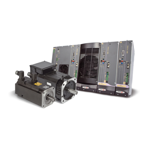
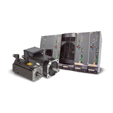
Fagor ACS Series User manual

ACBrushlessServoDriveSystemManual Ver:0002
ACa - 2 / 32
Preliminary
Index
Brushless AC Motors, FXM 4
1.1INTRODUCTION...........................................................................................................................4
1.2 MECHANICALDIMENSIONS.......................................................................................................6
1.3 POWERCONNECTORSANDENCODEROUTPUT....................................................................8
1.4 BRAKECHARACTERISTICS.......................................................................................................9
1.5SALESREFERENCE..................................................................................................................9
A.C. Servodrive 10
2.1INTRODUCTION..........................................................................................................................10
2.2 GENERALCHARACTERISTICS.................................................................................................11
2.3CONNECTORS...........................................................................................................................11
2.4 STATUSDISPLAY......................................................................................................................14
2.5PLACADECARACTERÍSTICAS Y REFERENCIACOMERCIAL...............................................15
2.6 INTERNALOPERATIONDIAGRAM............................................................................................16
Identity Module, IM 18
Installation 22
5.1 GENERALCONSIDERATIONS...................................................................................................22
5.2 ELECTRICALCONNECTIONS....................................................................................................23
5.3 ELECTRICALENCLOSUREDIAGRAM......................................................................................28
5.4 INITIALIZATIONANDSETUP......................................................................................................29

ACBrushlessServoDriveSystemManual Ver:0002 ACa - 3 / 32
Preliminary
Introduction
Fagoroffersyouawiderangeofservodrivesystems(ACbrushlessmotorandAnalogdrive)for
applicationsrequiringbetween0.65and32Nmatspeedsbetween1200rpmand4000rpm.
Thismanualdescribestheelementsindetailandguidesstepbystepthroughtheinstallationand
setupofthedrivesystem.
Wheninstalledforthefirsttime,itisagoodideatoreadthewholedocument.
Shouldyouhaveanydoubtsorquestions,pleasedonothesitatetocontactourtechniciansatany
ofoursubsidiariesworldwide.
ThankyouforchoosingFagor.
Declarationofconformity
Manufacturer: FagorAutomation,S.Coop.
BarriodeSanAndréss/n,C.P.20500,Mondragón-Guipúzcoa-(SPAIN)
Weherebydeclare,underourresponsibilitythattheproduct:
FagorACBrushlessServoDriveSystem.
consistingofthefollowingmodulesandmotors:
Servodrives: ACSSeries
ACMotors: FXMSeries
mentionedonthisdeclaration,
withthebasicrequirementsoftheEuropeanDirectives73/23/CEonLowVoltage(BasicSafety
Regulation,MachineryElectricalEquipmentEN60204-1:95)and89/336/CEonElectromagnetic
Compatibility(EN61800-3:1996,SpecificRegulationonElectromagneticCompatibilityforServo
DriveSystems).
InMondragón,February15th,2000

ACBrushlessServoDriveSystemManual Ver:0002
ACa - 4 / 32
Preliminary
1.1 INTRODUCTION
FXMseriessynchronousservomotors
areACBrushless,withpermanent
magnets.
Theyareidealforanyapplication
requiringgreatpositioningaccuracy.
Theyhaveasmoothtorqueoutput,has
nobrushes,highreliabilityandlow
maintenance.
Brushless AC Motors, FXM
-Meaningofthe
mountingcodes. - IP64meansthatitisprotectedagainstdustandagainst
waterjets.
-TheFclassisolationonthemotormaintainthedielectric
propertiesaslongastheworktemperaturestaysbelow
155°C(311°F).
FXM1 FXM3 FXM5 FXM7
Itsnormalprotectionlevel
isIP64,beingimmuneto
liquidsanddirt.
Thesystemincorporatesa
temperaturesensorfor
monitoringtheinternal
temperature.Theyalso
carryanoptional
electromechanicalbrake.
B5 V1 V3
Excitation Permanent rare earth magnets (SmCo)
Temperature sensor Thermistor
Shaft end Cylindrical with keyway. (Option: with no keyway)
Mounting Face flange
Mounting method B5-V1-V3 (as recommended by IEC-34-3-72)
Mechanical tolerances Normal class (IEC-72/1971)
Balancing Class N (Class R optional) (DIN 45665)
(balanced with the whole key)
Roller bearings' life 20,000 hours
Noise DIN 45635
Vibration resistance Withstands 1G along the shaft
and 3G sideways (G = 10 m/s² ).
Electrical Insulation Class F (155°C) (311°F)
Isolating resistance 500 Vdc, 10 MOhms or greater
Dielectric Strength 1500 Vac, one minute
Degree of Protection Overall: IP64 standard, IP54 with fan
Axis: IP64 standard, IP65 with oil seal
Storage temperature From -20°C to +80°C (-4°F / 176°F)
Working ambient temp. From 0°C to +40°C (32°F / 74°F)
Working ambient humidity From 20% to 80% (non condensing)
Brake Optional on all models
See "Brake Characteristics"
Feedback Differential TTL Encoder

ACBrushlessServoDriveSystemManual Ver:0002 ACa - 5 / 32
Preliminary
FXM11.40F.I0.xx0
FXM12.40F.I0.xx0
FXM13.40F.I0.xx0
FXM14.20F.I0.xx0
FXM14.40F.I0.xx0
FXM31.20F.I0.xx0
FXM31.40F.I0.xx0
FXM32.20F.I0.xx0
FXM32.40F.I0.xx0
FXM33.20F.I0.xx0
FXM33.40F.I0.xx0
FXM34.20F.I0.xx0
FXM34.40F.I0.xx0
FXM53.20F.I0.xx0
FXM53.40F.I0.xx0
FXM54.20F.I0.xx0
FXM54.30F.I0.xx0
FXM55.12F.I0.xx0
FXM55.20F.I0.xx0
FXM73.12F.I0.xx0
FXM73.20F.I0.xx0
FXM74.12F.I0.xx0
FXM75.12F.I0.xx0
Stall Torque
Peak
Torque
Rated
Speed
Stall Current
Peak
Current
Power
Torque
Constant
Acceleration
Time
Inductance
inter-phases
Resistance
inter-phases
Inertia
Weight
Peak Torque (Nm) for 0.5 seconds.
Mo Mp nNIo Imax Pow KT tac L R J P ACS-05 ACS-10 ACS-20 ACS-30
-Nm- -Nm- -rpm- -A- -A- -kW- Nm/A -ms- -mHr- Ohms
K
g.cm2 -Kg- -Nm- -Nm- -Nm- -Nm-
0,65 3,3 4000 1,1 5,5 0,3 0,6 23,2 70,0 8,1 1,8 3,3 3,0
1,3 6,5 4000 2,1 10,5 0,5 0,6 18,7 18,0 2,7 2,9 4,3 3,1
1,9 9,5 4000 3,1 15,5 0,8 0,6 21,6 8,3 1,5 4,9 6,4 3,1 6,1
2,6 13,0 2000 2,1 10,5 0,5 1,2 9,7 19,0 4,3 6,0 7,6 6,2
2,6 13,0 4000 4,2 21,0 1,1 0,6 19,3 4,9 1,1 6,0 7,6 6,2
2,0 10,0 2000 1,6 8,0 0,4 1,3 9,4 48,0 8,5 4,5 5,5 6,3
2,0 10,0 4000 3,2 16,0 0,8 0,6 18,8 13,0 2,4 4,5 5,5 3,1 6,3
3,9 19,5 2000 3,2 16,0 0,8 1,2 7,9 23,0 3,4 7,4 7,5 6,1 12,2
3,9 19,5 4000 6,3 31,5 1,6 0,6 15,9 5,8 0,8 7,4 7,5 6,2 12,4
5,8 29,0 2000 4,7 23,5 1,2 1,2 7,6 13,0 1,7 10,5 9,6 12,3 24,7
5,8 29,0 4000 9,4 47,0 2,4 0,6 15,2 3,6 0,5 10,5 9,6 12,3
7,9 39,5 2000 6,4 32,0 1,7 1,2 7,4 10,0 1,3 14,0 11,5 12,3 24,7
7,9 39,5 4000 12,7 63,5 3,3 0,6 14,8 2,6 0,3 14,0 11,5 12,4
10,0 50,0 2000 8,1 40,5 2,1 1,2 9,6 9,4 0,8 23,0 15,8 24,7 37,0
10,0 50,0 4000 16,1 80,5 4,2 0,6 19,3 2,4 0,2 23,0 15,8 18,6
13,6 68,0 2000 11,0 55,0 2,8 1,2 11,4 6,5 0,5 37,0 17,8 24,7 37,1
13,6 68,0 3000 16,4 82,0 4,3 0,8 17,1 3,1 0,3 37,0 17,8 24,9
17,0 85,0 1200 8,2 41,0 2,1 2,1 6,6 15,0 1,2 45,0 20,0 41,5 62,2
17,0 85,0 2000 13,7 68,5 3,6 1,2 11,1 5,8 0,4 45,0 20,0 37,2
19,5 97,5 1200 9,4 47,0 2,5 2,1 11,9 19,0 1,1 92,0 29,0 41,5 62,2
19,5 97,5 2000 15,7 78,5 4,1 1,2 19,8 6,9 0,4 92,0 29,0 37,3
26,0 130,0 1200 12,6 63,0 3,3 2,1 11,6 15,0 0,8 120,0 31,6 41,3 61,9
32,0 160,0 1200 15,5 77,5 4,0 2,1 12,6 11,0 0,6 160,0 36,0 61,9

ACBrushlessServoDriveSystemManual Ver:0002
ACa - 6 / 32
Preliminary
1.2 MECHANICAL DIMENSIONS
ACMOTORS

ACBrushlessServoDriveSystemManual Ver:0002 ACa - 7 / 32
Preliminary

ACBrushlessServoDriveSystemManual Ver:0002
ACa - 8 / 32
Preliminary
Thepowerconnectorincludesthebraketerminals(E,F).Voltagesbetween22and26volts
releasetheshaft.Wheninstallingthemotor,verifythatthebrakereleasestheshaftcompletely
beforeturningitforthefirsttime.
Connectingthemotorwindingsintheorderindicatedontheconnector(U,V,W),theshaftwill
turnclockwise(CWR).
Encoderconnector'sterminals9and10correspondtothethermistor.Itwatchesthemotor
heating.
1.3 POWER CONNECTORS AND ENCODER OUTPUT

ACBrushlessServoDriveSystemManual Ver:0002 ACa - 9 / 32
Preliminary
FXM 34.20F . I0 . 0 0 0
FAGOR AXIS MOTOR
I0 Incremental Encoder
Example:
FXM MOTORS
SIZE 1, 3, 5, 7
F
12 1200 rpm 20 2000 rpm
30 3000 rpm 40 4000 rpm
LENGTH
MAXIMUM
SPEED
WINDING
FEEDBACK TYPE
FLANGE AND
SHAFT 0
With Keyway
1
Without Keyway
BRAKE OPTION 0Without brake
1With standard brake (24 Vdc)
VENTILATION 0Without Fan
1.5 SALESREFERENCE
1.4 BRAKECHARACTERISTICS
Motor Type Torque Maximum
RPM Power On/Off
Delay Unlocking
voltage margin Inertia Weight
Nm (in.lb) rpm W (HP) ms Vdc Kg.cm2 (lb.in2) Kg (lbf)
FXM 1 2.5 (22.12) 10000 12 (0.016) 7/5
22 - 26
0,38 (0.13) 0,3 (0.66)
FXM 3 5 (44.25) 8000 16 (0.021) 15/7 1,06 (0.36) 0,6 (1.32)
FXM 5 12 (106.2) 6000 18 (0.024) 30/13 3,6 (1.23) 1.1 (2.42)
FXM 7 40 (354) 3600 35 (0.047) 100/30 31,8 (10.86) 3.5 (7.71)

ACBrushlessServoDriveSystemManual Ver:0002
ACa - 10 / 32
Preliminary
2.1 INTRODUCTION
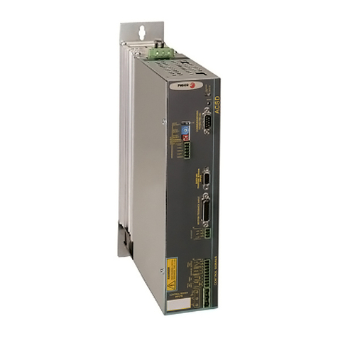
TheA.C.Servodriveisacompactspeeddrivewhichincludesthepowersupplyandisdesignedto
controlasingleBrushlessACSmotor.
Therearefourmodulesofdifferentpowerofferingpeakcurrentsof5,10,20and30Amps-rms-
andwhosemaincharacteristicsare:
- Three-phasepowersupplyfromMains.
- IndependentPowerandControlsupplies
- DynamicbrakingincaseofMainsfault.
- PWM IGBTs.
- IncrementalTTLEncoderfeedbackwith2500ppt.
- Programmableencoderoutput2/n(n,from2to16)
- VelocityorTorquecommand.
- Velocitycommandfilteredwithramps.
- Logicinputstocontrolthemotor(SpeedandDriveEnable).
- Galvanicisolationbetweenpowerandcontrol.
- Analogoutputstomonitorspeedandcurrent.
- Controlagainstexcessiveacceleration/deceleration.
- 7-segmentdisplaytomonitorthestatusoftheservodrivesystem.
- InternalfanactivationdependingontheDrive_Enablesignal.
- Protectionagainstfeedbackloss.
- Protectionagainstexcessivedrivetemperature.
- ProtectionagainstBusovervoltageorundervoltage.
- i2t protectioninthemotor.
- ProtectionoftheinternalBallastresistor(i2t).
- Short-circuitprotectioninthemotoroutputterminals.
- Protectionagainstaphasedrop.
A.C. Servodrive

ACBrushlessServoDriveSystemManual Ver:0002 ACa - 11 / 32
Preliminary
2.2 GENERAL CHARACTERISTICS.
(*) IP20 means that it is protected against particles with a diameter greater than 12.5 mm but
it doesn't against water splashes. The module must be located into the electrical cabinet.
2.3 CONNECTORS
PowerTerminals
POWERINPUTS220Vac, L1,L2,L3: MainPowerSupplyterminals.
POWEROUTPUTS, U,V,W: Motorpoweroutputterminals.
CurrentcontrolthroughPWM.Carrywavefrequencyof10kHz.
Connectthephasesbetweenthemotoranddrivethisway,U-U,V-V and W-W.
L+,Ri,Re: ExternalBallastterminals.
CONTROLPOWERINPUTS220Vac, L,N,Ground: AuxiliarPowerSupplyterminals.
Themaximumcablesectionatthesepowerterminalsis: 2.5mm2.
Totalisolationbetweenpowerandcontrolcircuits.
Fagor A.C.S. Drive
ACS-05 ACS-10 ACS-20 ACS-30
Rated output current 2,5 Amp-rms- 5 Amp-rms- 10 Amp-rms- 15 Amp-rms-
Peak output current (0.5 sec) 5 Amp-rms- 10 Amp-rms- 20 Amp-rms- 30 Amp-rms-
Power supply Three-phasic mains 50/60 Hz, from
220Vac -15% to 240Vac +10%
Consumption, Amp 2,5 Amp-rms- 5 Amp-rms- 10 Amp-rms- 15 Amp-rms-
Overvoltage protection 430 Vdc
Internal Ballast 112 Ohms 56 Ohms 28 Ohms 18 Ohms
Internal Ballast power 200 W
Ballast turn-on 416 Vdc
Heat-sink thermal protection 90°C (194°F)
Working Ambient temperature 5°C / 45°C (41°F / 113°F)
Storage temperature -20°C / 60°C (-4°F / 140°F)
Protection degree IP20 (*)
Module dimensions 67 x 280 x 245 mm
(2.48 x 11.8 x 9.05 inches)
Module weigth 3,85 Kg (8,5 lbs)

ACBrushlessServoDriveSystemManual Ver:0002
ACa - 12 / 32
Preliminary
ControlSignals.
±10Vvoltages, Pins1,2,3ofX1:Internalpowersupplysotheusercaneasilygeneratea
velocitycommand.Itoffersamaximumcurrentof20mAlimitedinternally.
Velocitycommand. Pins4,5,6ofX1: Itallowsarangevoltageof±10V andoffersan
impedanceof22kOhms.
Currentcommand. Pins4,7ofX1:Itallowsarangevoltageof±6.2V andoffersanimpedance
of10kOhms.Themotortorqueisdirectlyproportionaltothecurrent."Torquecommand".
Monitoring, Pins8,9,10ofX1: Voltageoutputsformonitoringmotorspeedandcurrent.
Voltagerangeof±10V.
Warningoutput, Pins1,2ofX2: Open-collectoroutputtosetawarningwhenthemotori2tor
theinternalBallastvigilanceisactivated.
Common,Pin5ofX2: ReferencepointforthefollowingEnablesignals:
DriveEnable,Pin4ofX2: At0Vdc,disablescurrentthroughthemotorwhichlosesitstorque.
SpeedEnable, Pin3ofX2: A0Vdc,forcesa"zerospeed"command.
Thesecontrolsignalsareactivatedat+24Vdc.
DriveOK.Pines6,7ofX2: RelaycontactthatcloseswhentheinternalstatusofthedriveisOK.
Itmustbeincludedintheelectricalmaneuver.
EncoderInput+MotorSensorTemp: Encodersignalinputfromthemotorforvelocity
feedback,andMotorthermistorsignals.
EncoderOutput+RatioSelect: EncoderoutputforclosingtheloopattheCNC.Theyare
splitedbythefactorselectedthroughtheB3-B0 dip-switches.
Themaximumsectionforthesecablesis 0.5mm2.
INTERNALFANACTIVATION: Theinternalfancoolsthepowerelectronics.Thefanturns-on
whentheDrive_Enablesignalisactivated.Thefanwillturn-offtwominuteslaterthanthe
Drive_Enablesignalhadturned-off.Thisprocedurereducesthestressofthefanandmakesthe
lifespanlonger.

ACBrushlessServoDriveSystemManual Ver:0002 ACa - 13 / 32
Preliminary
Acc/Dec.
Ramps
Max.
Current
Limit
PI.Gain
STATUS MESSAGES
. DRIVE DISABLED
L WAITING P. SUPPLY ??
0 SPEED DISABLED
1 RUNNING
ALARM MESSAGES (BLINKING)
2 MOTOR OVERTEMPERATURE
3 ENCODER FAULT
4 DRIVE OVERTEMPERATURE
5 MOTOR OVERLOAD
6 DRIVE OVERCURRENT
7 DRIVE OVERVOLTAGE
8 BALLAST OVERLOAD
9 INTERNAL FAULT
A POWER SUPPLY FAULT
Max.
Speed
Offset
ADJUST
CONTROL - SIGNALS
RATIO
SELECT
ENCODER
INPUT
+
MOTOR SENSOR
TEMP
C
E
SPEED
DRIVE
ENABLES MONITORDR.OK
10
9
8
7
6
5
4
3
2
1
COMMON
Vel-
CURRENT
Vel+
+10V
-10V
20mA out
N
L
Identification Module IM.
-See correspondent section-
Status Display.
Status and Alarm
messages from
the Status Display.
X1
Connector for
the encoder input
signals.
Connector for
encoder signal
output to CNC.
Auxiliar Power
Supply input
terminals.
Connectors
and front panel.
CONTROL
POWER
INPUTS
N
L
9
8
10
VELOCITY
CURRENT
7
6
DR.OK
4
3
5
SPEED
DRIVE
COMMON
-10 V
+10 V 2
1
3
Vel +
Vel -
5
4
6
7
CURRENT
±10 V
power
Commands
Monitoring.
Enables
Drive OK.
COMMANDS
CONTROL POWER
INPUTS
220 Vac
7
6
5
4
3
2
1
WARNING
OUTPUT
VELOCITY
CURRENT
ENCODER
OUTPUT
1
2
C
EWarning
DANGER
HIGH VOLTAGE 310Vdc
DISCHARGE TIME = 1 min.
X2
X1
X2
B3
B2
B1
B0
RESET
CROWARD (ON)
VBUS (OK)
STATUS AC Servodrive
X3
RATIO
SELECT
B3
B2
B1
B0
Dividing factor
of the encoder signal.
More significant Bit
Less significant Bit
1
2
3
4
A
*A
B
*B
5
6
7
8
Z
*Z
9+5 Vdc
10 W
15
12
13
14 Tp
V
11 GND:Tp
U
*U
*V
*W
16 Chassis
1
2
3
4
A
*A
B
*B
5
6
7
8
Z
*Z
11 0 V
01

ACBrushlessServoDriveSystemManual Ver:0002
ACa - 14 / 32
Preliminary
2.4 STATUS DISPLAY
Afterthat,adigitisshownsteady(statusmessage)orblinking(warning).
Statusmessages:(steady)
Theunitisunderpower,Drive_EnableandSpeed_Enablepinsaredeactivated,(0Voltsat
pins 3 and 4 of X2). Themotorhasnotorque.
Waiting.ThedriveiswaitingfortheBuscharge.Thecontrolcircuitsarepowered.Ifthisstatus
laststoolong,reviewthepowerconnectiontoMainsandtheBallastresistorone.
Speed_Enableoff (0Voltsatpin3ofX2),andDrive_Enableon(+24Vatpin4ofX2).
Themotorhastorquewithnovelocitycommand.
EverythingisOK.Drive_EnableandSpeed_EnableareactiveandtheMotorrespondsto
thecommand.
Warning:(blinking)
Motorovertemperature.
Solutions:Smooththedutycycle.Improveitscooling.
NoFeedback.
Solutions:Checkthatthefeedbackcableandconnectorsareproperlyconnected.
Driveovertemperature.
Solutions:Smooththedutycycle.Improveitscooling.
Motoroverloadwarning. (fastblinking)
Themotori2tprotectionsisbeenexceeded.Thiseventactivatesthedigitaloutput"Warning
output"(1and2pinsofX2).60secondslater,theerrorwillbeactivated.
Motoroverloaderror.Afterthepreviouswarning,themotori2tprotectionhasgoneoff.The
motorhasmaintainedanaveragecurrentgreaterthanthemaximumallowedfortoolong.The
motorhasbeenworkingbeyonditsratedcurrent.
Itisa7-segmentdisplayformonitoringtheDrivestatus.
PoweringtheequipmenttheStatusDisplayshowsathreedigitsequence:
Driveidentification,Ballastresistorconfiguration,Numberofencoderpulsesperturn,
Currentthresholdformotori2tprotection.
ACS-05 Internal
Ballast
ACS-10
ACS-20
ACS-30
External
Ballast
Reserved
2500 ppt
1 Amp / 9 Amp/
15 Amp14 Amp
13 Amp12 Amp
11 Amp10 Amp

ACBrushlessServoDriveSystemManual Ver:0002 ACa - 15 / 32
Preliminary
DriveOvercurrent.Therehasbeenaninstantaneouscurrentpeakgreaterthanthemaximum
allowed.GetincontactwithFagorAutomation.
DriveOvervoltage.TheinternalBusvoltagehasexceeded430Vdc.
Solutions:TheBallastcircuitmaybedefectiveorthesupplyvoltageistoohigh.Theexternal
Ballasthasn`tbeeninstalledcorrectly,oritsvalueisnotright.
Ballastoverloadwarning (fastblinking)
TheBallasti2tprotectionisactivated.Ifitgoeson,theerrorwillbeactivated.
Ballastoverloaderror.Afterthepreviouswarning,theBallasti2tprotectionhasgoneoff.
Solutions:InstallanexternalBallastresistance,andsettheRAPT=10Ohms.
Internalfault.Internalcontrolerror,ortheRITvalueiswrong.
Phasedroped.Anyofthemainphaseshasdroped,oramainsmicrocuthasbeenlongerthan
100ms.
Note:Allthealarmsarelatched,theunit(controlandpowersupply)mustbepoweredoffand
turnedbackonafter30seconds.OrpushtheResetbutton.
2.5 SPECIFICATIONS PLATE AND SALES REFERENCE
Examplesofthe
specsplatethatcomeswith
eachFagorACSdrive.
Codesofthe sales
referenceofFagorACS
drives.
"PC","PP","VAR"and"FR"indicatemanufacturingrelatedaspects(hardwaredesignversions)
thatareusefulfortechnicalconsultationsandrepairs.
A.C.S. DRIVES Example: ACS - 05
A.C. SERVODRIVE
CURRENT Rated Peak (0.5 sec)
05 2,5 Amp 5 Amp
10 5 Amp 10 Amp
20 10 Amp 20 Amp
30 15 Amp 30 Amp
AC SERVODRIVE
Fa
g
or Automation S. Coop.(Spain)
MODEL: ACS-05
S.N.: 202-1904001
PC
00A FRVAR
00A
PP
00A
INPUT :
OUTPUT: 3 X 220 VAC / 50-60 Hz
0-200 VAC
Io
Imax 5
10 Amp
Amp W: 3,85 K
g

ACBrushlessServoDriveSystemManual Ver:0002
ACa - 16 / 32
Preliminary
2.6 INTERNAL
OPERATION
DIAGRAM
Ballast.
L3
L1
L2
CURRENT
Pin 9, X1
MOTOR
OUTPUT
POWER
INPUT
Pin 5, X1
Pin 6, X1
VEL
Pin 1, X2
Pin 2, X2
Max.
Speed
Max. Current
Limit
J2 abc
CURRENT
Pin 7, X1
Pin 4, X1
Acc/Dec
Ramps PI. Gain
J3
a
b
ENCODER
INPUT
ENCODER
OUTPUT ASTATUS
DISPLAY
DR.OK
Pin 1
Pin 2
Pin 3
-10V
+10V
Pin 6, X2
Pin 7, X2
WARNING
OUTPUT
DRIVE
SPEED Pin 3, X2
Offset
RTV1
RIT
RAPT
J4
a
b
c
A
Pin 5, X2
Pin 4, X2
Control
de PWM
COMMON COMMON
RAD1
CAD1 RAP1
CAI1
RAJFV
VEL
VELOCITY
Pin 8, X1
Pin 5, X2
B3-B0
RTV1
Protections:
Feedback Error
Drive Overtemperature
Motor Overload
Drive Overcurrent
Drive Overvoltage
Undervoltage
Balast overload
Internal Fault
Power Supply Fault
X1
W
U
V
L+ Ri Re
Pin 10, X1
Rectifer Power
stage.
PWM
Internal
supply
Power-down
detection
Bus
Voltage
Ramp
generator
Speed PI
Overspeed
Control
Bus
Voltage
Logic circuits for
diagnosis & control.
Current
PI
Frequency / Voltage

ACBrushlessServoDriveSystemManual Ver:0002 ACa - 17 / 32
Preliminary
User notes:

ACBrushlessServoDriveSystemManual Ver:0002
ACa - 18 / 32
Preliminary
ThiscardisinsertedintotheACSdrivemodule.Itspassivecomponentsandjumpersadjustthe
driveelectronicstotheFXMmotoritgoverns.ThereisanIMcardforeachcorrectcombinationof
FXMmotorandACSdriveasshownonthenextpage.TheIM-000boardisusedforsettingDCS
Driveswithnon-Fagormotors.Thecalculationofthepassivecomponentsisdescribedonthenext
page.
Thepotentiometersaccessiblefromtheoutsideallowafinaladjustmentoftheservodrivesystem.
Thecomponentlayoutofthiscardandtheirfunctionsaredescribednext.
Passivecomponents:
NC: Empty.
RIT: Itsetsthecurrentvaluefromwhichthei2tprotectionstartsintegrating.RIThasdifferent
valuesforeachmotor.
RAJFV: Itsetstherelationshipbetweenthefrequenciesoftheencoderpulsesandtheequivalent
voltageintheinternaldrivecircuits.
RAPT: ItdeterminesiftheBallastisaninternalorexternalresistor.IfanexternalBallastis
installed RAPT should be equal to 10 Ohms. An open RAPT means internal Ballast. The protection
againsti2texceedingdoesn'tworkwithexternalBallast.
RTV1: (notavailableyet)Itsetsthedriveacordingtotheencoderpulsesperturnused.IfRTV1
isshort-circuitedthedrivewillbesetfor3000ppt,ifRTV1isopenneditwillbesetfor2500ppt.
RAD1,CAD1: TheysetthederivativecompensationatthevelocityPI.
RAP1,CAI1: TheysettheproportionalandintegralactionofthevelocityPI.
Jumpers(inbold,defaultposition):
J2: Rampgenerator, active (ab),ornot(bc).
J3: Activatestheaccelerationovershootingcontrol.Active(ab).
J4: Selectorforthetypeofcommand.Currentcommand(ab)orvelocity(bc).
IdentityModule, IM
Acc/Decc Ramps
Max. Current Limit
PI Gain
Max. Speed
Offset
J3 J4
ab abc
abc
J2
NC
RIT
RAJFV
RAPT
RTV1
RAD1
CAD1
RAP1
CAI1
- IM Board -

ACBrushlessServoDriveSystemManual Ver:0002 ACa - 19 / 32
Preliminary
Thesearethenamesoftheidentity
modules(IM)foreachMotor-Driveset. Andthesearethevaluesofthepassive
componentsoneachofthosecards.
IDENTITY MODULE Example: IM - 3420F - 10
IDENTITY MODULE
MOTOR TYPE
DRIVE TYPE
MI Board RIT RAJFV
ACS-05 ACS-10 ACS-20 ACS-30
FXM11.40F.I0.xx0 IM-1140F-05 Open 6,2K
FXM12.40F.I0.xx0 IM-1240F-05 470K 6,2K
FXM13.40F.I0.xx0 IM-1340F-05 IM-1340F-10 220K 6,2K
FXM14.20F.I0.xx0 IM-1420F-05 470K 12K
FXM14.40F.I0.xx0 IM-1440F-10 120K 6,2K
FXM31.20F.I0.xx0 IM-3120F-05 470K 12K
FXM31.40F.I0.xx0 IM-3140F-05 IM-3140F-10 220K 6,2K
FXM32.20F.I0.xx0 IM-3220F-05 IM-3220F-10 220K 12K
FXM32.40F.I0.xx0 IM-3240F-10 IM-3240F-20 68K 6,2K
FXM33.20F.I0.xx0 IM-3320F-10 IM-3320F-20 100K 12K
FXM33.40F.I0.xx0 IM-3340F-20 39K 6,2K
FXM34.20F.I0.xx0 IM-3420F-10 IM-3420F-20 68K 12K
FXM34.40F.I0.xx0 IM-3440F-20 18K 6,2K
FXM53.20F.I0.xx0 IM-5320F-20 IM-5320F-30 47K 12K
FXM53.40F.I0.xx0 IM-5340F-30 12K 6,2K
FXM54.20F.I0.xx0 IM-5420F-20 IM-5420F-30 27K 12K
FXM54.30F.I0.xx0 IM-5430F-30 12K 8,2K
FXM55.12F.I0.xx0 IM-5512F-20 IM-5512F-30 47K 20K
FXM55.20F.I0.xx0 IM-5520F-30 15K 12K
FXM73.12F.I0.xx0 IM-7312F-20 IM-7312F-30 39K 20K
FXM73.20F.I0.xx0 IM-7320F-30 12K 12K
FXM74.12F.I0.xx0 IM-7412F-20 IM-7412F-30 18K 20K
FXM75.12F.I0.xx0 IM-7512F-30 12K 20K
RAP1 = 82K CAI1 = 100nF RAPT = Open

ACBrushlessServoDriveSystemManual Ver:0002
ACa - 20 / 32
Preliminary
Adjustmentpotentiometers:
Acc/DecRamps:Toadjusttherampfilteringthevelocitycommand.Rampswithadurationofup
to10secondsmaybeappliedfora10voltstepofanalogvoltage.
Turningthispotclockwisemeanssmootherbehavior(longerramp).
WATCHOUT!IfjumperJ2oftheidentitymoduleissetinthe(bc)position,norampswillbe
applied.
Max.CurrentLimit:Eachdriveisfactorysettoprovidethemaximumcurrenttothemotorwhich
correspondstothemaximumvalueofthecurrentcommand.Thisadjustmentmaybeusedto
decrease(-100%)thevalueofthatcurrentlimit.
Turningthispotclockwiseallowsmorecurrenttoflowthroughthemotor.
PIGain:ForadjustingtheoverallgainofthevelocityPI.
Turningthispotclockwiseincreasesthegainand,therefore,makesthesystemperkier.
Max.Speed:Everydriveisfactorysetsothemotorturnsatitsmaximumspeedwhenapplied
maximumvelocitycommand.
Inthiscase,thispotwillbeturned3/4ofitsfulltravel.Therefore,itmaybeusedtolimitorforce
slightlythemaximummotorspeed.
Turningthispotclockwiseallowsgreaterspeed.
Offset: Tocompensateforthedifferencebetweenthevelocitycommandandtheactualmotor
speed.
This manual suits for next models
66
Table of contents
Other Fagor Servo Drive manuals
Popular Servo Drive manuals by other brands

Danaher Motion
Danaher Motion SERVOSTAR CD-LITE user manual

Sanyo Denki
Sanyo Denki PY Series Installation and operation manual

YASKAWA
YASKAWA E-V Series user manual

Glentek
Glentek SMA5005 Installation guide, operation & service manual

Lenze
Lenze DeviceNet 9400 Communications manual

LinMot
LinMot C1400-CI-VS-0S-YYY installation guide