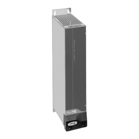
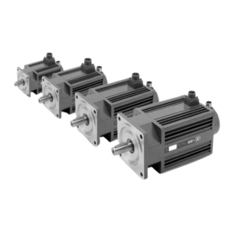
Fagor DCM21 User guide

DC Servo Drive System Manual Ver: 0009 DC - 1/32
Fagor Automation, S.Coop.
Ver: 0009
DC Servo Drive
System Manual.

DC Servo Drive System Manual Ver: 0009
DC - 2/32
DC Motors, DCM 4
1.1 INTRODUCTION ........................................................................................................................... 4
1.2 GENERALCHARACTERISTICS .................................................................................................. 5
1.3 TORQUE-SPEEDCURVES......................................................................................................... 6
1.4 TERMINALBOX........................................................................................................................... 7
1.5 ENCODEROUTPUTCONNECTOR ............................................................................................. 7
1.6 CHARACTERISTICS PLATE ANDSALESREFERENCE ............................................................. 8
1.7 SERVICEINSTRUCTIONS........................................................................................................... 8
D.C. Servodrive 9
2.1 INTRODUCTION ........................................................................................................................... 9
2.2 GENERALCHARACTERISTICS .................................................................................................10
2.3 CONNECTORS ...........................................................................................................................11
2.4 STATUS DISPLAY ......................................................................................................................13
2.5 INTERNALOPERATIONDIAGRAM ............................................................................................14
2.6 SPECIFICATIONS PLATE ANDSALES REFERENCE................................................................15
Motor-Drive set 17
Identity Module, IM 18
Installation 21
5.1 GENERALCONSIDERATIONS ...................................................................................................21
5.2 ELECTRICALCONNECTIONS ....................................................................................................22
5.3 ELECTRICALENCLOSUREDIAGRAM ......................................................................................26
5.4 INITIALIZATIONANDSETUP ......................................................................................................27
Mechanicals Dimensions 28
Index

DC Servo Drive System Manual Ver: 0009 DC - 3/32
Introduction
Fagoroffersyouawiderangeofservodrivesystems(motoranddrive)forapplicationsrequiring
between1and12Nmatspeedsbetween1200rpmand4000rpm.
Thismanualdescribestheelementsindetailandguidesstepbystepthroughtheinstallationand
setupofthedrivesystem.
Wheninstalledforthefirsttime,itisagoodideatoreadthewholedocument.
Shouldyouhaveanydoubtsorquestions,pleasedonothesitatetocontactourtechniciansatany
ofoursubsidiariesworldwide.
ThankyouforchoosingFagor.
Declarationofconformity
Manufacturer: FagorAutomation,S.Coop.
BarriodeSanAndréss/n,C.P.20500,Mondragón-Guipúzcoa-(SPAIN)
Weherebydeclare,underourresponsibilitythattheproduct:
FagorDCServoDriveSystem.
consistingofthefollowingmodulesandmotors:
Servodrives: DCSSeries
DCMotors: DCMSeries
mentionedonthisdeclaration,
withthebasicrequirementsoftheEuropeanDirectives73/23/CEonLowVoltage(BasicSafety
Regulation,MachineryElectricalEquipmentEN60204-1:95)and89/336/CEonElectromagnetic
Compatibility(EN61800-3:1996,SpecificRegulationonElectromagneticCompatibilityforServo
DriveSystems).
InMondragón,September22nd,2000

DC Servo Drive System Manual Ver: 0009
DC - 4/32
1.1 INTRODUCTION
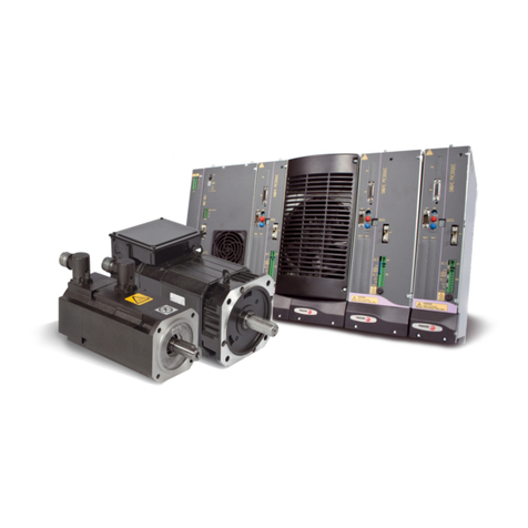
FagorDCMmotors(DC)are
especiallydesignedtobe
controlledbyFagorDC
servodrives.
TheseDCmotorsareeasier
andlessexpensivetogovern
thanbrushlessmotors.
Itsmechanicsisanindustrial
standard.
DC Motors, DCM
DCM4 DCM2DCM5
(*)Thediagrambelowshows
themeaningofthemounting
codes.
(**)IP44meansthatitisprotectedagainstparticleswith
adiametergreaterthan1mmandagainstwatersplashes
inalldirections.
Winding voltage 100-130 Vdc
Number of poles 2 (DCM2); 4 (DCM4 and DCM5)
Shaft end Cylindrical with keyway.
Mounting Face flange.
(meets IEC-34- 7-72) B14, V18, V19 on DCM2;
B5, V1, V3 on DCM4 and DCM5.
Mechanical tolerance Standard class (meets IEC 72/1971)
Bearings life 10000 hours
Balancing Class N (meets DIN 45665)
(balancing with keyway)
Noise Meets IEC 34-9-72
Brake (optional) 24 Vdc
Electrical Insulation Class F
Degree of protection IP44 (**)
Operating temperature range From 0°C to +40°C (32°F to 104°F)
Maximum overtemperature 130°C (266°F)
Thermal switch N. C. 120°C (248°F)
13 Amp (250 Vac); 18 Amp (24 Vdc)
Maximum altitude 1000 meters (1281 ft) above sea level.
Feedback 20 Volt/Krpm tachometer
2500 lines/turn encoder TTL
(***)TheFclassisolationonthemotormaintainthe
dielectricpropertiesaslongastheworktemperature
staysbelow155°C(311°F).
B14/B5 V18/V1 V19/V3

DC Servo Drive System Manual Ver: 0009 DC - 5/32
1.2 GENERAL
CHARACTERISTICS DCM4
42.12A
(Kg·m2)·10E-3
Total weight with tachometer
Maximum speed
MECHANICAL PARAMETERS
Inertia
Kg
rpm
5,2
0,95
4.000
7,3 9,5
1,8
4.000
2,7
2.500
2,1
9,3
1.200 2.000 3.000 1.200
V/(rad/s)
Nm/A
rad/s2
UNIT
Continuous stall current
Armature resistance w/o brushes
Armature resistance with brushes
Back EMF
Armature inductance
Peak current
Voltage constant
mH
A
A
V
ohms
(2)
ohms
Mechanical time constant
Electrical time constant
Theoretical acceleration at peak torque
Thermal time constant
ELECTRICAL PARAMETERS
THERMAL PARAMETERS
Torque constant (KT) (2)
min
ms
ms
Continuous stall torque
Peak stall torque
MOTOR PARAMETERS
(1) Nm
Nm
8,5
19,5
4,7
103
1,75
0,24
1,6
74
40
8,8
105
32,5
7,2
113
0,7
0,55
0,25
1,4
0,43
1,2
0,24
45
4.950
28,8
4,8
0,25
55
0,43
60
5.555
5,7
20
5.185
21,2
5
7,521
22
2,9
110,5
36,5
4,7
111
5,90
5,80
0,88
1,90
1,80
0,53
133,5
55
6,9
110
35
5,2
110,5
0,80
0,70
0,35
2,6
2,5
0,88
0,88 0,53
50
9.190
3,5
16
9.190
3,9
14,2
0,35 0,88
9.190
4,3
13,7
9.687
5
10,7
DCM2
1,12
4,7
21.40A
DCM21
2,2
10
22.40A
3,1
14
23.25A
DCM22 DCM23
41.20A
DCM41
41.12A
2,6
19,3
2,5
19,3
41.30A
2,4
19,3
4,6
31
2.0003.000
12,4
3,2
2.000
17
4,8
1.200
21
9,6
1.200
23
2.000
13
1.200
11.250
25
52
7,8
118
80
11,0
120
0,98
0,9
0,56
0,45
0,38
0,38
39
55
7,3
123
95
12,0
123
1,22
1,12
0,98
0,54
0,44
0,58
9.687
0,56
60
0,38
9.687
5,1
11,1
4,4
11,7
0,98
70
0,58
11.250
7,5
6,8
5,5
8,8
6,7
50
9,5
125
1,10
1,03
1,00
62,4
83
15,0
125
70
12,0
125
0,42
0,36
0,60
0,77
0,70
1,00
1,00
5.000
6
10,4
0,60
80
1,00
90
5.000
5,7
12,1
5.400
7,6
10
43.20A42.30A42.20A
4,4
29
4,2
31
DCM42
43.12A
7,2
54
7,0
54
DCM43
DCM5
DCM51
9,5
50
51.12A
9
50
51.20A
12
70
52.12A
DCM52
(2)
(2)
(2)
(2)
TACHOMETER PARAMETERS -T0-
(2) ohms
Armature resistance
Temperature coefficient
Minimum load resistance value Kohms
% / °C
Voltage Gradient
Voltage Ripple (3)
V / Krpm
%
26
6
0,02
20 ± 5%
<1,5
ENCODER PARAMETERS -E0-
Signal
Resolution 2500 lines per turn
3.000
11.250
1,3
140
17,4
123
0,25
0,18
0,39
0,39
6
8,7
43.30A
6,8
54
Brake mass
Parking torque
Power Supply voltage, (power)
(3) Peak-to-peak value / average value.
Measured with filter at max. motor speed
(1) Ambient temperature: 40°C
(
2
)
Tolerance ±10 %
Rated torque Nm 0,9
Rated power Kw 0,37
1,5 2
0,62 0,52
2,3 2 1,6
0,29 0,42 0,5
4,5 4 3,5
0,56 0,83 1,1 0,85 1,15 1
1,25
6,8 5,5 8
4
1,25 1,38
611
Important: The torque offered by the motors could be limited
by the maximum current of the drive governing them. See table on page 17.
square wave TTL
+5 Vdc 20 mA max.
Power supply DC
+5 Vdc 200 mA max.
Kg
BRAKE PARAMETERS
Vdc, (W)
Nm
0,6
24, (12)
2
1
24, (15)
5
3
24, (25)
20
DCM2 DCM4 DCM5
Hold/Release time sec 5/7 7/15 18/55
Inertia Kg.cm20.38 1.05 8.5

DC Servo Drive System Manual Ver: 0009
DC - 6/32
1.3 TORQUE-SPEED CURVES
1. Workareaincontinuous
dutycycleS1.Torque
availableincontinuous
mode.
2. Workareainintermittent
dutycycle.Torqueavailable
incyclicaccelerationand
deceleration.
3. Workareainsporadic
accelerationand
deceleration.Workinginthis
area,reducesthelifespan
ofthebrushes.
L.S. Demagnetizinglimitat25°C(77°F).TheDCSdrive,equippedwiththeproperIMboard,watches
themotorsoitneverexceedsthosedemagnetizingcurrents.
1
0.5
10
50
04000rpm
DCM21 DCM22 DCM23
Nm
5
30001000
DCM41
DCM52
1
0.5
10
50
04000rpm
Nm
5
30001000
1
0.5
10
50
03000rpm
Nm
5
25001000
DCM43
1
10
100
0rpm
Nm
5
1000 2000 3000
3
2
20
50
1200
DCM42
1
10
100
0rpm
Nm
5
1000 2000 3000
3
2
20
50
1200 1
10
100
0rpm
Nm
5
1000 2000 3000
3
2
20
50
1200
DCM52
1
10
300Nm
50
100
0 rpm 1000 2000 30001200 1
10
300Nm
50
100
0 rpm 1000 2000 30001200
3
2
3
1
2
1
2
1
2
1
2
1
3
2
1
3
2
1
1
2
3
LS

DC Servo Drive System Manual Ver: 0009 DC - 7/32
Includesterminalsfor:
Powerinputforthemotorwinding. Inputforelectromechanicalbrake
Tachovoltageoutput. Safetythermalcontact
1.4 TERMINAL BOX
Whenthemotorwindingissuppliedwiththepolarityindicatedontheterminalbox(B+,E-),the
rotorturnsclockwise(CWR,clockwiserotation),asshowninthediagram.And,forthisturning
direction,thetachogeneratesavoltageatitsterminals(Tacho)alsowiththepolarityindicatedon
the box (+, -).
Theelectromechanicalbrakereleasesthemotorshaftwhenapplied24Vdc.
Whenstationary,itholdsthemotorshaft.
Thethermalswitchwatchesthearmaturetemperature.
1.5 ENCODER OUTPUT CONNECTOR
Front View
TTL Encoder
DC Motor
987
6
5
4
3
21
6
5
4
3
2
1
7
8
9
B
A
Zt
Clockwise Rotation (CWR)
si
g
nals:
CWR
Clockwise Rotation
+5V
*A
B
*B
Z
*Z
0V
A
Pin Si
g
nal
NC
E
BMotor
Power
Tacho
Thermal
Brake
DC
CWR
Clockwise Rotation
E
B
G
M
D
C
N.C.
Tacho
Brake
Thermal
Motor
Power
Ch.
Ch.
DC-IND-2/28 inductance
onl
y
needed with the motors
FXM 42.30A and 43.30A

DC Servo Drive System Manual Ver: 0009
DC - 8/32
1.6 CHARACTERISTICS PLATE AND SALES REFERENCE
Exampleoftheplatethat
comeswitheachDCMmotor.
Salesreferencedescription
forDCMmotors
1.7 SERVICEINSTRUCTIONS
Thebrushesmustbecheckedforthefirsttimeafterbeingrunningfor500hoursand,then,every
1000hours.Onemustcheckthewaytheysweep,theirsurfaceandthatofthecollector.
Thelifespanofthebrushesdependonhowtheyareusedandonambientconditions.
Theymustbereplacedwithbrushesofsamequalityanddimensions:10mmfortheDCM2,and
11mmfortheDCM4andDCM5.
TYPE: DCM42.20A.E0.000
Permanent Magnet D.C. Servomotor
SN: E190057
Mo 4.4 Nm
Mp 29 Nm Io: 7.8 A MAX. RPM: 2000
B.E.M.F.: 118 V
TACHO: V/KRPM BRAKE: V A
Ip: 52 A
KT: 0.56 Nm/A Iso.Cl.: F
DC MOTORS Example DCM 4 2. 20 A. E0. 0 0 0
DIRECT CURRENT MOTOR
MOTOR SIZE 295 mm
4115 mm
5153 mm
LENGTH 1, 2, 3 See drawings
MAXIMUM SPEED 12 1200 rpm 30 3000 rpm
20 2000 rpm 40 4000 rpm
25 2500 rpm
WINDING AStandard
FEEDBACK E0 TTL Encoder (standard)
T0 Tacho
F0 Encoder and Tacho (not available)
FLANGE AND SHAFT 0With keyway (standard)
1Without keyway
BRAKE OPTION 0Without brake (standard)
1With brake (24 Vdc)
POWER CONNECTION 0Terminal box
1Power connector (not available)

DC Servo Drive System Manual Ver: 0009 DC - 9/32
2.1 INTRODUCTION
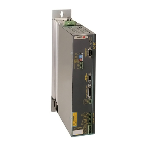
TheD.C.Servodriveisacompactspeeddrivewhich
includesthepowersupplyandisdesignedtocontrola
singleDCmotor.
Therearetwomodulesofdifferentpowerofferingrated
currentsof8and14Ampsandwhosemaincharacteristics
are:
- Three-phasepowersupplythroughatransformer.
- PWM Mosfets.
- Encoderfeedback(standard)ortacho.
- VelocityorTorquecommand.
- Velocitycommandfilteredwithramps.
- Logicinputstocontrolthemotor.
- Galvanicisolationbetweenpowerandcontrol
- Analogoutputstomonitorspeedandcurrent.
- Controlagainstexcessiveacceleration/deceleration.
- Dynamicbrakingduringmainsfailures.
- Protectionagainstmotorcurrentdrifts.
- Protectionagainstfeedbackloss.
- Protectionagainstexcessivetemperature,Busvoltageandoutputcurrent.
- 7-segmentdisplaytomonitorthestatusoftheservodrivesystem.
D.C. Servodrive

DC Servo Drive System Manual Ver: 0009
DC - 10/32
Maximumpeakcurrent.
Thedrivewithstandsamaximumpeakcurrentinrepetitivecycles
Thefirstgraphshowsthedutycycleanalyzedonamotorwithoutload.
ThefollowinggraphshowsthemaximumpeakcurrentallowedattheDCSdependingonthe
durationofthepulseandfordifferenttemperatures.
Inanycase,thedurationofthemaximumcurrentpulse(T1)mustnotexceed4.5seconds.
DCS-08
12
10
16
18
0
Amp
14
0.1
8
60.2 0.3 0.4 0.5 0.6
DCS-14
15
10
25
30
0
Amp
20
0.1
50.2 0.3 0.4 0.5 0.6
T2
T1
+rpm
-rpm
T1/T2
T1/T2
25°C
45°C
25°C
45°C
2.2 GENERAL CHARACTERISTICS
(*) IP20 means that it is protected against particles with diameter greater than 12.5 mm; but not
against water splashes. In other words, the equipment must be mounted inside the electrical
enclosure.
Fagor D.C.Servodrive
DCS-08 DCS-14
Power supply 110 Vac between phases. 50/60 Hz
(range 94-120 Vac)
Consumption, Amperes -RMS- 9 16
Maximum in-rush current 350 Amp for 10 msec.
Maximum output voltage 150 Vdc
Rated output current 8 Amp 14 Amp
Peak current (4.5 sec) 16 Amp 28 Amp
Overvoltage protection 192 V
Overcurrent protection 20 A 33 A
Internal Ballast 10 Ohms, 200 W
Ballast trigger 184 V
Thermal protection 90°C (194°F)
Ambient temperature 5°C / 45°C (41°F / 113°F)
Storage temperature -20°C / 60°C (-4°F / 140°F)
Insulation IP20 (*)
Module width 62 x 300 x 230 mm
(2.48 x 11.8 x 9.05 inches)
Module weight 3,5 Kg (7.76 lbs)

DC Servo Drive System Manual Ver: 0009 DC - 11/32
2.3 CONNECTORS
PowerTerminals
MotorOutput: ±150Vdcoutputvoltageappliedtothemotor
Outputcurrenttothemotor(continuous/peakfor4.5seconds):
DCS-08: 8A/16A
DCS-14: 14A/28A
MaximumcurrentwithPWMonacarrierfrequencyof10kHz.
Watch outfor polarity.Seepage23.
PowerInput: 94-120Vacthree-phasesupplythroughatransformer.Seepage22.
Themaximumcablesectionatthesepowerterminalsis: 2.5mm2.
Totalisolationbetweenpowerandcontrolcircuits.
ControlSignals
±10Vvoltages, Pins1,2,3:Internalpowersupplysotheusercaneasilygenerateavelocity
command.Itoffersamaximumcurrentof20mAlimitedinternally.
Velocitycommand. Pins4,5,6:
Currentcommand. Pins4,7:
Seepage25.Themotortorqueisdirectlyproportionaltothecurrent."Torquecommand".
Tachofeedback.Pins8,9: Velocityfeedbackinputfromthetachointothedrive.Becarefulwith
thepolarity.Seepage24.
Monitoring. Pins10,11,12: Voltageoutputsformonitoringmotorspeedandcurrent.Voltage
rangeof±10V.Seepage23.
Common,Pin15: ReferencepointforthefollowingEnablesignals:
DriveEnable,Pin14: At0Vdc,disablescurrentthroughthemotorwhichlosesitstorque.
SpeedEnable,Pin13: A0Vdc,forcesa"zerospeed"command.
Thesecontrolsignalsareactivatedat+24Vdc.
DriveOK.Pins16,17: RelaycontactthatcloseswhentheinternalstatusofthedriveisOK.It
mustbeincludedintheelectricalmaneuver.Seepage26.
EncoderInput: Encodersignalinputtothemotorforvelocityfeedback.
EncoderOutput: EncoderoutputforclosingtheloopattheCNC.Seepage24.
Themaximumsectionforthesecablesis 0.5mm2.

DC Servo Drive System Manual Ver: 0009
DC - 12/32
Acc/Dec.
Ramps
Max.
Current
Limit
PI.Gain
. DRIVE DISABLED
0 SPEED DISABLED
1 RUNNING
2 MOTOR INSULATION FAULT
3 FEEDBACK ERROR
4 DRIVE OVERTEMPERATURE
5 MOTOR OVERLOAD
6 DRIVE OVERCURRENT
7 DRIVE OVERVOLTAGE
E UNDERVOLTAGE
Max.
Speed
Offset
ADJUST
DC Servodrive
STATUSCONTROL - SIGNALSPOWER TERMINALS
ENCODER
OUTPUT
ENCODER
INPUT
VELOCITY
CURRENT
SPEED
DRIVE
ENABLES MONITORDR.OK
17
16
15
14
13
12
11
10
9
8
7
6
5
4
3
2
1
COMMON
VEL-
CURR
VEL+
+10V
-10V
20mA out
MOTOR
OUTPUT
POWER
INPUT
3x110Vac.
L1
L3
L2
DANGER
HIGH VOLTAGE 150Vdc
DISCHARGE TIME = 1 min.
M
T
POWER
INPUT
L3
L1
L2
MOTOR
OUTPUT
11
10
12
VELOCITY
CURRENT
17
16
DR.OK
14
13
15
SPEED
DRIVE
COMMON
-10 V
+10 V 2
1
3
VEL+
VEL-
5
4
6
7
CURR 8
9
+5V
6
5
4
3
2
1
15
9
*A
B
*B
Z
*Z
0V
A
11
1
2
3
4
A
*A
B
*B
5
6
7
8
Z
*Z
11 0 V
COMMANDS
Not
Connected
Front panel and
Connectors.
Identity module: IM.
- See corresponding section -
Drive status display.
Meaning of the
possible messages
at the Status display.
Encoder output
connector for the
CNC.
Power terminals
to supply current
to the motor.
Connector for drive
control signals.
Encoder feedback
input connector.
Power terminals
to get energy from
mains.
±10 V
power
supply.
Commands.
Tacho
feedback.
Monitoring.
Enables.
Drive OK.

DC Servo Drive System Manual Ver: 0009 DC - 13/32
2.4 STATUS DISPLAY
Itisa7-segmentdisplayformonitoringtheDrivestatus.
Theunitisunderpower,the"DriveEnable"pinisdeactivated,(0Voltsatpin14).
Themotorhasnotorque.
"SpeedEnable"off(0Voltsatpin13),and"DriveEnable"(+24Vatpin14).
Themotorhastorquewithnovelocitycommand.
EverythingisOK."DriveEnable"and"SpeedEnable"areactiveandtheMotorrespondsto
thecommand.
Currentleakfrompowerlinestoground.
Solutions:carryoutthemotormaintenanceprocedures.Checktheinsulationofthepower
cables.
NoFeedback.
Solutions:CheckthatjumperJ1selectsthefeedbackmodebeingused.Checkthatthe
feedbackcableandconnectorsareproperlyconnected.Checkthatthewindingcircuitisnot
open.Whenworkinginvelocitycommandmode,makesurethatjumperJ4isinthe(bc)
position.Whenworkingintorquecommandmode,makesurethattheRAPTresistorofthe
identitymoduleisshort-circuited.
InthecaseofanEncoder,checkthepolarityofthevoltageappliedtothewindingandthat
thesignalpairs(A,*A)and(B,*B)arenotinterchanged.
Inthecaseoftachofeedback,checkthepolarityofthewindingandthatofthetacho.Check
thatthetachoisnotopenordefective.
Driveovertemperature.
Solutions:Smooththedutycycle.Improveitscooling.Theunitwillreturntoitsnormalrunning
statuswhenitcoolsdownbelow78°C(172°F).
Motoroverload.TheI·Tprotectionhasgoneoff.Inotherwords,themotorhasmaintainedan
averagecurrentgreaterthanthemaximumallowed(IomaxM)fortoolong.Thedutycycleis
toodemandingforthecapabilitiesofthemotor.Themotorisworkingbeyonditsrated
current.
Solutions:Smooththedutycycle.LimitmotoraccelerationwithACC/DECRAMPS.Limitthe
commands,MAX.CURRENTLIMITandMAX.SPEED.DecreasetheRIT,thusallowingthe
systemtofurtherforcethemotor.
Overcurrent.Therehasbeenaninstantaneouscurrentpeakgreaterthanthemaximumallowed
accordingtothetableonpage11.
Solutions:LimitmotoraccelerationwithACC/DECRAMPS.Ifthemotorhaslowinductanceand
thecurrentrippleisexcessive,addaninductanceinserieswiththewindingcircuit(thisis
neverrequiredwithFagorDCMmotors).
Overvoltage.Foraninstant,theinternalBusvoltagehasexceeded193V.
Solutions:TheBallastcircuitmaybedefectiveorthesupplyvoltageistoohigh.
Low-voltage.Thesupplyvoltageistoolow.
Notes:
Allthealarmsexceptthe 4. andE.arelatchedandtheunitmustbepoweredoffand,after30
seconds,turnedbackon.
J1,J4,RAPT,ACC/DECRAMPS,MAX.CURRENTLIMIT,MAX.SPEEDandRITareelementsfor
adjustingtheservodrivesystemandtheyaredescribedinthesectionon"theIdentityModuleIM".

DC Servo Drive System Manual Ver: 0009
DC - 14/32
2.5 INTERNAL
OPERATION
DIAGRAM
Ballast.
Rectifer Power
stage.
PWM
L3
L1
L2
CURRENT
Pin 12
MOTOR
OUTPUT
POWER
INPUT
Ramp
generator
Pin 5
Pin 6
VEL
Pin 8
Pin 9
Max.
Speed
Max. Current
Limit
J2 abc
CURR Pin 7
Pin 4
Acc/Dec
Ramps PI. Gain
J3
a
b
Speed PI
J1abcde
ENCODER
INPUT
ENCODER
OUTPUT AProtections:
Motor Insulation Fault
Feedback Error
Drive Overtemperature
Motor Overload
Drive Overcurrent
Drive Overvoltage
Undervoltage
Logic circuits for
diagnosis & control.
STATUS
DR.OK
Pin 1
Pin 2
Pin 3
Internal
supply
-10V
+10V
Pin 16
Pin 17
TACHO
INPUT
DRIVE
SPEED Pin 13
Overspeed
Control
Offset
RTV1
Frequency / Voltage RIT
RAPT
J4
a
b
c
A
Pin 15 Pin 15
Pin 14
PWM
Control
Current
PI
Power-down
detection
COMMON COMMON
RAD1
CAD1 RAP1
CAI1
RAJFV
Bus
Voltage
VEL
VELOCITY
Pin 11
Bus
Voltage

DC Servo Drive System Manual Ver: 0009 DC - 15/32
2.6 SPECIFICATIONS PLATE AND SALES REFERENCE
Examplesofthe specsplate
thatcomeswitheachFagor
DCdrive.
Codesofthe sales
referenceofFagorDC
drives.
"PM","FV","VAR"and"FR"indicatemanufacturingrelatedaspects(hardwaredesignversions)
thatareusefulfortechnicalconsultationsandrepairs.
D.C. SERVODRIVES Example: DCS - 08 - E0
D.C. SERVODRIVE
CURRENT Rated Peak (4.5 sec)
08 8 Amp 16 Amp
14 14 Amp 28 Amp
FEEDBACK T0 Basic drive. Read
y
to
control motors with tacho
E0 Drive especiall
y
equipped
to also control motors
with Encoder (E0 and F0). Standard.
DC SERVODRIVE
Fa
g
or Automation S. Coop.(Spain)
MODEL: DCS-14-E0
S.N.: 22-19040001
PM
00A FRVAR
00A
FV
00A
INPUT :
OUTPUT: 3 X 110 VAC / 50-60 Hz
0-150 VDC
Io
Imax 14
28 Amp
Amp W: 3,5 K
g
DC SERVODRIVE
Fa
g
or Automation S. Coop.(Spain)
MODEL: DCS-08-T0
S.N.: 22-19040000
PM
00A FRVAR
00A
INPUT :
OUTPUT: 3 X 110 VAC / 50-60 Hz
0-150 VDC
Io
Imax 8
16 Amp
Amp W: 3,5 K
g

DC Servo Drive System Manual Ver: 0009
DC - 16/32

DC Servo Drive System Manual Ver: 0009 DC - 17/32
Motor-Driveset
Ratedandpeaktorque
Thecharacteristicsofratedandpeaktorquesofthemotorsareoftenlimitedbythecurrent
capabilitiesoftheDrivecontrollingthem.
Thistableconsidersthesepossiblelimitations.
DCS-08 DRIVE DCS-14 DRIVE
Speed Stall Torque Peak Torque Stall Torque Peak Torque
MOTORS -rpm- -Nm- -Nm- -Nm- -Nm-
DCM21.40A 4000 1.12 3.8
DCM22.40A 4000 2 4 2.2 7
DCM23.25A 2500 3.1 6.8 3.1 12
DCM41.12A 1200 2.6 15.2
DCM41.20A 2000 2.5 8.5
DCM41.30A 3000 2.4 5.6
DCM42.12A 1200 4.6 15.2
DCM42.20A 2000 4.4 8.9 4.4 15.6
DCM42.30A 3000 4.2 10.6
DCM43.12A 1200 7.2 15.6 7.2 27.4
DCM43.20A 2000 7 16.2
DCM43.30A 3000 5.5 10.9
DCM51.12A 1200 9.5 28
DCM51.20A 2000 8.4 16.8
DCM52.12A 1200 12 28

DC Servo Drive System Manual Ver: 0009
DC - 18/32
ThiscardisinsertedintotheDCSdrivemodule.Itspassivecomponentsandjumpersadjustthe
driveelectronicstotheDCMmotoritgoverns.
ThereisanIMcardforeachcorrectcombinationofDCMmotorandDCSdriveasshownonthe
nextpage.TheIM-000boardisusedforsettingDCSDriveswithnon-Fagormotors.The
calculationofthepassivecomponentsisdescribedonthenextpages.
Thepotentiometersaccessiblefromtheoutsideallowafinaladjustmentoftheservodrivesystem.
Thecomponentlayoutofthiscardandtheirfunctionsaredescribednext.
Passivecomponents:
NC: Empty.
RIT: ItsetsthecurrentvaluefromwhichtheI·Tprotectionstartsintegrating.Ifthisresistoris
short-circuited,thisprotectionisremoved.
RAJFV: Whenusingencoderfeedback,itsetstherelationshipbetweenthefrequenciesofthe
encoderpulsesandtheequivalentvoltageintheinternaldrivecircuits.
RAPT: Thesystemisprotectedagainstmotorrunawayshoulditlosefeedback.Thisresistor
setstheoverspeedvaluetriggeringthisprotection.ThesmallerthevalueoftheRAPTthemore
tolerantthesystemis.Ifshort-circuited,thisprotectionwillberemoved.Whenworkingincurrent
commandmode,thisRAPTmustbeshort-circuited.
RTV1: ItadaptsthevoltagegeneratedbythetachototheinternalDrivecircuits.
RAD1,CAD1: TheysetthederivativecompensationatthevelocityPI.
RAP1,CAI1: TheysettheproportionalandintegralactionofthevelocityPI.
Jumpers(inbold,defaultposition):
J1: Feedbacktypeselector. Viaencoder (bc). Viatacho(de).
J2: Rampgenerator,active (ab),ornot(bc).
J3: Activatestheaccelerationovershootingcontrol.Active(ab).
J4: Selectorforthetypeofcommand.Currentcommand(ab)orvelocity(bc).
IdentityModule, IM
Acc/Decc Ramps
Max.CurrentLimit
PI Gain
Max.Speed
Offset
J3 J4
abcde
ab abc
J1 abc
J2
NC
RIT
RAJFV
RAPT
RTV1
RAD1
CAD1
RAP1
CAI1
- IM Board -

DC Servo Drive System Manual Ver: 0009 DC - 19/32
Adjustmentpotentiometers:
Acc/DecRamps:Toadjusttherampfilteringthevelocitycommand.Rampswithadurationofup
to10secondsmaybeappliedfora10voltstepofanalogvoltage.
Turningthispotclockwisemeanssmootherbehavior(longerramp).
WATCHOUT!IfjumperJ2oftheidentitymoduleissetinthe(bc)position,norampswillbe
applied.
Max.CurrentLimit:Eachdriveisfactorysettoprovidethemaximumcurrenttothemotorwhich
correspondstothemaximumvalueofthecurrentcommand.Thisadjustmentmaybeusedto
decreasethevalueofthatcurrentlimit.
Turningthispotclockwiseallowsmorecurrenttoflowthroughthemotor.
PIGain:ForadjustingtheoverallgainofthevelocityPI.
Turningthispotclockwiseincreasesthegainand,therefore,makesthesystemperkier.
Max.Speed:Everydriveisfactorysetsothemotorturnsatitsmaximumspeedwhenapplied
maximumvelocitycommand.
Inthiscase,thispotwillbeturned3/4ofitsfulltravel.Therefore,itmaybeusedtolimitorforce
slightlythemaximummotorspeed.
Turningthispotclockwiseallowsgreaterspeed.
Offset: Tocompensateforthedifferencebetweenthevelocitycommandandtheactualmotor
speed.
Thesearethenamesoftheidentity
modules(IM)foreachMotor-Driveset. Andthesearethevaluesofthepassive
componentsoneachofthosecards.
IM Board RIT RAJFV RTV1
DCS-08 DCS-14 DCS-08 DCS-14
DCM21.40A IM-2140A-08 DCM21.40A 75K 5,6K 82K
DCM22.40A IM-2240A-08 IM-2240A-14 DCM22.40A 39K 68K 5,6K 82K
DCM23.25A IM-2325A-08 IM-2325A-14 DCM23.25A 43K 82K 10K 39K
DCM41.12A IM-4112A-08 DCM41.12A 130K 22K 10K
DCM41.20A IM-4120A-08 IM-4120A-14 DCM41.20A 75K 130K 12K 27K
DCM41.30A IM-4130A-08 IM-4130A-14 DCM41.30A 47K 91K 8,2K 56K
DCM42.12A IM-4212A-08 IM-4212A-14 DCM42.12A 68K 130K 22K 10K
DCM42.20A IM-4220A-08 IM-4220A-14 DCM42.20A 39K 75K 12K 27K
DCM42.30A IM-4230A-14 DCM42.30A 56K 8,2K 56K
DCM43.12A IM-4312A-08 IM-4312A-14 DCM43.12A 43K 82K 22K 10K
DCM43.20A IM-4320A-14 DCM43.20A 47K 12K 27K
DCM43.30A IM-4330A-14 DCM43.30A 39K 8,2K 56K
DCM51.12A IM-5112A-14 DCM51.12A 62K 22K 10K
DCM51.20A IM-5120A-14 DCM51.20A 39K 12K 27K
DCM52.12A IM-5212A-14 DCM52.12A 47K 22K 10K
General purpose: IM-0000 RAPT = 15K RAP1 = 82K CAI1 = 100nF

DC Servo Drive System Manual Ver: 0009
DC - 20/32
Maximum Speed: 1200 rpm
Example of calculation:
RAJFV (KΩ) =
RAJFV calculation:
This calculation is independent of whether the maximum speed is later limited with Max.Speed
or not.
This calculation is OK for velocity commands of ±10V.
If for example, the command is ±8V for a maximum speed of ±1200 rpm, the previous
calculation will result in a maximum speed of 1200·10/8 = 1500 rpm.
This RAJFV must be of 1/4 Watt
68,4 ·106
(Pulses/turn) ·Nmax ·1.15 Encoder pulses per turn: 2500
RAJFV (KΩ) = 68,4 ·106
2500 ·1200 ·1.15 = 19.8 KΩ
DCS-08 drive
Example of calculation:
RIT (KΩ) =
RIT calculation:
This RIT must be of 1/4 Watt
150
In ·K DCM41.20 motor : In = 4.72 Amp
- 10 where:
K = 0.39 (DCS-8)
K = 0.22 (DCS-14)
RIT (KΩ) = 150
4.72 ·0.39 - 10 = 71.5 KΩ
"In" is the rated current of the motor according to the characteristics table or the current used in
a duty cycle considered nominal.
AdjustmentofIMcomponentsforgoverningNon-Fagormotors
Maximum Speed: 1200 rpm
Tacho Constant: 20 V/Krpm
Example of calculation:
1200 ·1.3 ·0.02 = 31.2
RTV1 = 31.2 - 22 = 9.2 KΩ / 0.25 W
RTV1 = Vmaxtac - 22 (KΩ)
Vmaxtac = Nmax ·1.3 ·Ktac
RTV1 calculation:
This calculation is independent of whether the maximum speed is later limited with Max.Speed
or not.
This calculation is OK for velocity commands of ±10V.
If, for example, the command is ±8V for a maximum speed of ±1200 rpm, the previous
calculation will result in 1200·10/8 = 1500 rpm.
This RTV1 must be of 1/4 Watts
Graph for calculating the RTV1 resistor when
using a 20 V/Krpm tacho.
(the one carried by the Fagor motors mentioned
in this manual)
10
Nmax (rpm)
RTV1
(kΩ)
RTV1
(for Ktac = 20 V/Krpm)
1000 80
2000
3000
4000
20 30 40 50 60 70
Codesofthesalesreference fortheidentitycards:
IDENTITY MODULE Example: IM - 4120A - 14
IDENTITY MODULE
MOTOR TYPE
DRIVE TYPE
This manual suits for next models
7
Table of contents
Other Fagor Servo Drive manuals