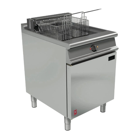
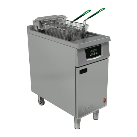
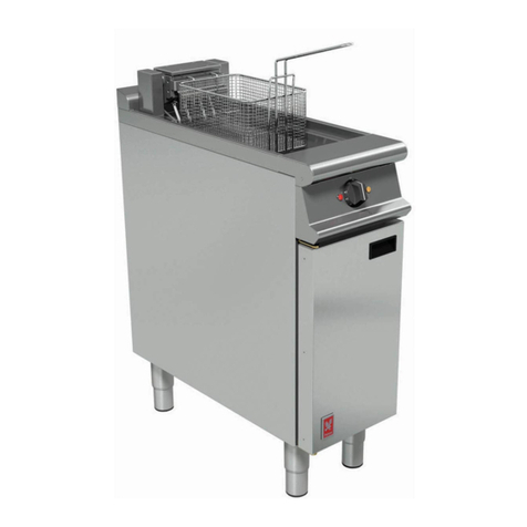
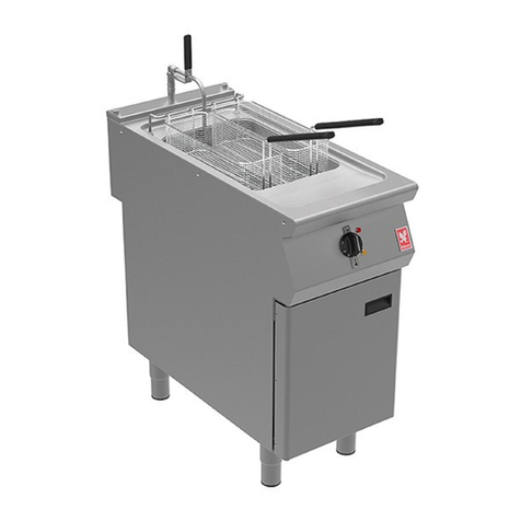
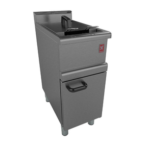
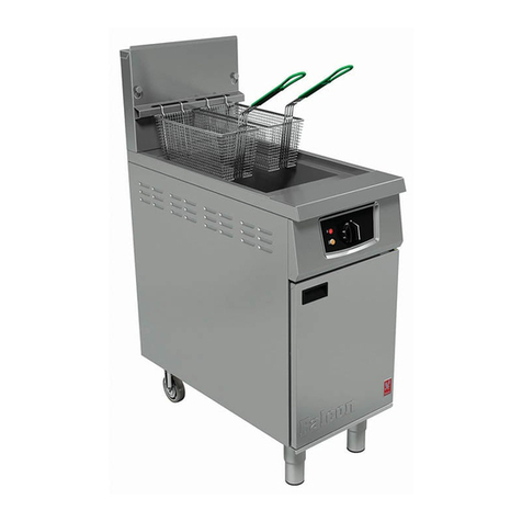
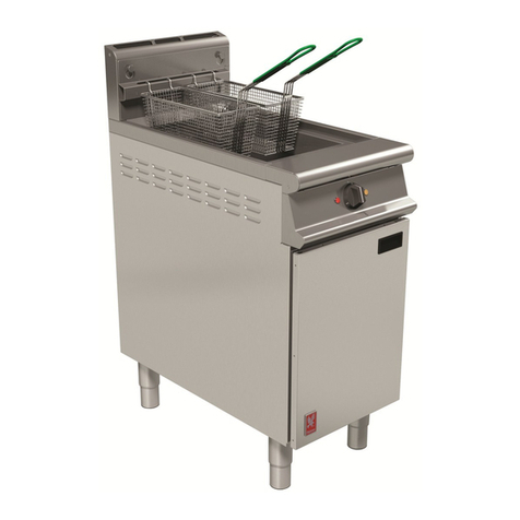
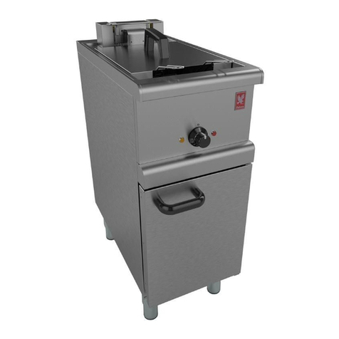
Falcon G3840 User guide

1
T100806 Ref.17
These appliances must be installed and serviced by a qualified person as stipulated by the Gas Safety
(Installation & Use) Regulations.
IMPORTANT
The installer must ensure that the installation of the appliance is in conformity with these instructions
and National Regulations in force at the time of installation. Particular attention MUST be paid to –
Gas safety (Installation & Use) regulations
I.E.E. Regulations for Electrical Installations
Health & Safety at work, etc Act
Electricity at Work Regulations
Local and National Building Regulations
Fire precaution Act
Detailed recommendations are contained in DW172 Institute of Gas Engineers published documents:
IGE/ UP/ 1, IGE/ UP/ 2, IGE/ UP/ 4, BS6173 and BS5440
These appliances have been UKCA/CE-marked based on compliance with the Gas Appliance
Regulations/Product Safety and Metrology Regulations, Electrical and Electromagnetic Compatibility
(EMC) Regulations/Directives for the Countries, Gas Types and Pressures as stated on the data plate.
WARNING - TO PREVENT SHOCKS, ALL APPLIANCES, GAS OR ELECTRIC, MUST BE EARTHED.
On completion of the installation, these instructions should be left with the Engineer-in-Charge for
reference during servicing. Further to this, the user instructions should be handed over to the user,
having had a demonstration of the operation and cleaning of the appliance.
PREVENTATIVE MAINTENANCE CONTRACT
To obtain maximum performance from this unit regular servicing of the appliance should be undertaken to ensure
correct operation, it is functioning as intended, and safe to use. We recommend servicing in accordance with SFG20
Maintenance Schedules and as a minimum, after 2,500 hours of use, or annually, whichever comes first and that a
maintenance contract be arranged with an appointed service contact. Visits may then be made at agreed intervals
to carry out adjustments and repairs.
We recommend that the oil level sensor (UK Patent Serial No. GB2584184)in the G3840X/G3840FX
model should be serviced annually.
WEEE Directive Registration No. WEE/DC0059TT/PRO
At end of unit life, dispose of appliance and any replacement parts in a safe
manner,
via a licenced waste handler. Units are designed to be dismantled
easily and recycling of
all material is encouraged whenever practicable.
This equipment is ONLY FOR PROFESSIONAL USE, and shall be operated by QUALIFIED
persons. It is the responsibility of the supervisor or equivalent to ensure that users wear SUITABLE
PROTECTIVE CLOTHING and to draw attention to the fact that some parts will, by necessity,
become VERY HOT and will cause burns if touched accidentally.
FalconFoodserviceEquipment
Wallace View, Hillfoots Road, Stirling, FK9 5PY,Scotland
Phone: 01786 455200
G3840/G3840X/G3840F/G3840FX
FRYERS
INSTALLATION,SERVICING
and USER INSTRUCTIONS
CAUTION: Read the instructions before using the appliance

2
IMPORTANTINFORMATION
ELECTRICAL SAFETY AND ADVICE REGARDING SUPPLEMENTARY ELECTRICAL PROTECTION
Commercial kitchens and foodservice areas are environments where electrical appliances may be located
close to liquids, or operate in and around damp conditions or where restricted movement for installation
and service is evident.
The installation and periodic inspection of the appliance should only be undertaken by a qualified, skilled
and competent electrician; and connected to the correct power supply suitable for the load as stipulated
by the appliance data label.
The electrical installation and connections should meet the necessary requirements to the local electrical
wiring regulations and any electrical safety guidelines.
We recommend:-
•Supplementary electrical protection with the use of a type A residual current device (RCD)
•Fixed wiring appliances incorporate a locally situated switch disconnector to connect to, which is easily
accessible for switching off and safe isolation purposes. The switch disconnector must meet the
specification requirements of IEC 60947.
Your attention is drawn to:-
BS 7671:2018–Guidance Note 8 - 8.13 : Other locations of increased risk
It is recognized that there may be locations of increased risk of electric shock other than those specifically
addressed in Part 7 of BS 7671. Examples of such locations could include laundries where there are
washing and drying machines in close proximity and water is present, and commercial kitchens with
stainless steel units, where once again, water is present.
Where because of the perception of additional risks being likely, the installation designer decides that an
installation or location warrants further protective measures, the options available include:
•Automatic Disconnection of Supply (ADS) by means of a residual current device having a residual
operating current not exceeding 30mA;
•Supplementary protective equipotential bonding; and
•Reduction of maximum fault clearance time.
The provision of RCDs and supplementary bonding must be specified by the host organization’s appointed
installation designer or electrical contractor and installed by a suitably qualified and competent electrician
so as to comply with Regulations 419.2 and 544.2

Training and competence
To help ensure the safe use of this appliance there is a requirement for you to provide whatever
information, instruction, training and supervision as is necessary to ensure, so far as is reasonably
practicable, the health and safety of all users.
For further help and information on training and competence we would refer you the Health and Safety
Executive website; www.hse.gov.uk document ref: health and safety training INDG345. International
customers should default to the health and safety guidelines provided by your government body.
Risk assessment
As part of managing the health and safety of your business you must control any risks identified in your
commercial kitchen. To do this you need to think about what might cause harm to people and decide
whether you are taking reasonable steps to prevent that harm. This is known as risk assessment. It is
important to consider the environment around the product as well as the product itself. For example oil
or food spills will present a significant risk so users so the need to immediately clean up such spills must
be reflected in staff training.
For further help and information on risk assessments we would refer you to you the Health and Safety
Executive website; www.hse.gov.uk document ref: risk assessment INDG163. International customers
should default to the health and safety guidelines provided by your government body.
Cleaning and maintenance
When removing heavy items to aid cleaning or maintenance particular care should be taken. A manual
handling risk assessment is the best way to determine the level of risk to anyone using or maintaining
this equipment. To help with such an evaluation we have included the weights of individual components
that may present significant risk.
For further help and information on manual handling and associated risk assessment we would refer
you to you the Health and Safety Executive website; www.hse.gov.uk document ref: manual handling
at work INDG143. International customers should default to the health and safety guidelines provided
by your government body.
The cleaning of fryers or other products that use hot oil present significant risks to end users and
particular care should be taken. Cold water and hot oil for example are an explosive mix and should be
avoided at all costs.
Other useful references for health and safety issues
www.hse.gov.uk
Essentials of health and safety at work ISBN978
Noise at work INDG362
Safe systems of work
Other notes added to the body of the instructions

4
CONTENTS
1.0 INSTALLATION........................................................................................................................................................6
1.1 MODEL NUMBERS, NETT WEIGHTS & DIMENSIONS..........................................................................................6
1.2 SITING.................................................................................................................................................................6
1.2.1 Anti-tipping Kit.........................................................................................................................6
1.2.2 Clearances.............................................................................................................................. 7
1.3 VENTILATION......................................................................................................................................................7
1.4 GAS SUPPLY (All Models) ...................................................................................................................................7
1.5 ELECTRICAL SUPPLY............................................................................................................................................8
1.6
TOTAL RATED HEAT INPUTS...............................................................................................................................9
1.7 INJECTOR SIZES ..................................................................................................................................................9
2.0 ASSEMBLY and COMMISSIONING..........................................................................................................................9
2.1 ASSEMBLY ..........................................................................................................................................................9
2.2 CONNECTION TO A GAS SUPPLY........................................................................................................................9
2.3 CONNECTION TO AN ELECTRICAL SUPPLY .......................................................................................................10
2.4 STARTING UP....................................................................................................................................................10
2.4.1 G3840/F Fryer Control Panel (See Figure 2).........................................................................10
2.4.2 G3840X/G3840FX Fryer Control Panel (See Figure 3)..........................................................11
2.4.3 G3840 & G3840F - Additional Controls - (See Figure 4)........................................................11
2.4.4 G3840 and G3840F Controller Diagnostic
Indicators............................................................. 12
2.5 PRE-COMMISSIONING CHECK..........................................................................................................................12
2.5.1 Checking Controller Operation ..............................................................................................13
2.5.2 Checking Oil Filtration Pump................................................................................................. 13
2.6 TEMPERATURE LIMIT THERMOSTAT................................................................................................................13
2.7 OIL LEVEL SENSOR (G3840X/G3840FX only)....................................................................................................13
2.8 INSTRUCTION TO USER ....................................................................................................................................13
3.0 SERVICING AND CONVERSION .............................................................................................................................14
3.1 GAS CONVERSION ............................................................................................................................................15
3.2 INTEGRAL COMPONENTS.................................................................................................................................15
3.3 ACCESS PROCEDURES.......................................................................................................................................15
3.4 GAS CONTROL VALVE.......................................................................................................................................15
3.5 PILOT/IGNITER/SENSOR ASSEMBLY.................................................................................................................15
3.6 BURNER............................................................................................................................................................16
3.7 BURNER RESET SWITCH, ON/OFF SWITCH
and FILTRATION PUMP SWITCH...................................................16
3.8 BURNER LOCK OUT NEON................................................................................................................................16
3.9 OPERATING THERMOSTAT (Thermistor) PROBE..............................................................................................16
3.10 TEMPERATURE PCBCONTROLLER (Operating Thermostat Board) ...................................................................16
3.11 MAINS ON and HEAT DEMAND NEONS............................................................................................................17
3.12 DRAIN VALVE....................................................................................................................................................17
3.13 FILTRATION PUMP ...........................................................................................................................................17
3.14 IGNITION CONTROL BOX..................................................................................................................................17
3.15 TEMPERATURE LIMIT THERMOSTAT................................................................................................................17

5
3.16 OIL LEVEL SENSOR (G3840X/G3840FX only, Figure 5) .....................................................................................18
3.17 TOP UP AND LOW OIL LEVEL LEDS (G3840X/G3840FX only, Figure 5) ............................................................18
3.18 OIL LEVEL SENSOR EVALUATION UNIT (G3840X/G3840FX only, Figure 5)......................................................18
3.19 RELAYS & RELAY BASES (G3840X/G3840FX only, Figure 5) .............................................................................18
3.20 POWER SUPPLY UNIT (G3840X/G3840FX only, Figure 5) ................................................................................18
4.0 SPARES .................................................................................................................................................................19
5.0 CRITICAL DIMENSIONS.........................................................................................................................................20
6.0 OPERATING INSTRUCTIONS .................................................................................................................................21
6.1 APPLIANCE CONTROLS.....................................................................................................................................23
6.2 LIGHTING and OPERATION
Safety Precautions................................................................................................23
6.2.1 Lighting Instructions ..............................................................................................................23
6.2.2 Fryer maximum basket loading.............................................................................................. 23
6.2.3 Using the Controller...............................................................................................................23
7.0 CHANGING/FILTERING THE OIL............................................................................................................................24
7.1 STARTING THE FILTRATION PROCESS ..............................................................................................................24
7.2 G3840F MODEL................................................................................................................................................25
8.0 CLEANING and MAINTENANCE ............................................................................................................................26
8.1 CLEANING THE APPLIANCE...............................................................................................................................26
9.0 PREPARATION OF
SOLID FATS / SHORTENING.....................................................................................................28
10.0 COOKING HINTS ...................................................................................................................................................29
11.0 WIRING DIAGRAMS..............................................................................................................................................30
11.1 G3840 WIRING DIAGRAM ................................................................................................................................30
11.2 G3840X WIRING DIAGRAM..............................................................................................................................31
11.3 G3840F WIRING DIAGRAM ..............................................................................................................................32
11.4 G3840FX WIRING DIAGRAM ............................................................................................................................33
11.5 G3840 CIRCUIT DIAGRAM................................................................................................................................34
11.6 G3840X CIRCUIT DIAGRAM..............................................................................................................................35
11.7 G3840F CIRCUIT DIAGRAM ..............................................................................................................................36
11.8 G3840FX CIRCUIT DIAGRAM ............................................................................................................................37

6
1.0 INSTALLATION
UNLESS OTHERWISE STATED, PARTS WHICH HAVE
BEEN PROTECTED BY
THE MANUFACTURER ARE NOT TO BE ADJUSTED BY THE INSTALLER.
Please ensure that any plastic coatings are removed prior to use. Before operation, pan requires to be
thoroughly cleaned and dried.
Discolouration of heated parts is caused by factory
testing to ensure a satisfactory unit. It does not affect
quality or performance.
1.1 MODEL NUMBERS, NETT WEIGHTS & DIMENSIONS.
Model
Width (mm)
Depth (mm)
Height (mm)
Weight (kg)
G3840 Fryer
400
770
1090
83
G3840X Fryer
400
770
1090
85
G3840F Fryer
400
770
1090
94
G3840FX Fryer
400
770
1090
96
Pan oil capacity:
18 litres cold, good quality oil (to –MIN- mark)
1.2 SITING
Each unit must be installed on a firm level floor in a well- lit draught free position. The fryer should
be installed in a freestanding position to prevent any possibility of
sideways tipping under force.
The means of restraint may be the manner of installation, such as connection to
a battery of
appliances or installing the fryer in an alcove, or by separate means, such as adequate ties.
Anti-tipping Kit
An anti-tipping mechanism is supplied with unit. If these are to be fitted, the brackets must be fitted
to locate the fryer in the correct position relative to any walls as detailed below. Fixing holes are
provided in the fryer base to accommodate the bracket. The bracket should be fitted
as detailed
in Figure 1. The retaining chain has a quick release eyelet. Secure to fixing point and secure
bracket to floor after alignment with anti-tipping device attached to
the fryer. Adjust to slide below
floor bracket.
Figure 1 - Anti-tipping Bracket

7
Clearances
The unit requires a clearance of at least 150mm all round between unit and any walls. The unit
must only be installed next to non combustible walls. A minimum vertical clearance of 750mm
should be allowed between top edge of flue outlet and any overlying combustible surface.
Important
If fryer is to be installed with other appliances then the instructions for
every model should be consulted to
determine the necessary clearance
to any wall or overlying surface.
Some appliances require greater clearance distances than others. The
largest clearance will therefore determine overall distance for a
complete suite of
adjoining appliances.
1.3 VENTILATION
This appliance MUST be installed with sufficient ventilation to prevent the occurrence of
unacceptable concentrations of substances harmful to health in the room in which they are
installed. Installer must consult any additional local / national regulations.
The fresh air requirement for this appliance at a rate of 2M³/hour per kW is 44 M³ is as follows:
COMBUSTION AIR REQUIREMENTS
APPLIANCE
VENTILATION RATE
G3840
44 m3/h
G3840X
44 m3/h
G3840F
44 m3/h
G3840FX
44 m3/h
1.4 GAS SUPPLY (All Models)
To be checked at installation, gas conversion or repair.
Note: Governor setting may be checked at burner manifold without the need to remove the right
hand side panel.
To adjust appliance pressure;
The SIT gas valve, situated at rear RH side of unit and accessible by removing RH side, has
an in-built governor.
The supply pressure should be checked at valve inlet test nipple using a manometer.
Burner pressure should be set at test nipple on burner manifold using a manometer.
Checking / Setting values are indicated below (for either natural or propane gas).
This is achieved by removing brass dust screw from valve governor and adjusting governor
accordingly using an approved VDE insulated screwdriver - clockwise rotation increases pressure.
(see illustration) insulated
Warning: To avoid risk of electric shock, all adjustments to the governor
should be made with the appliance switched off and unplugged.
Note: Propane (I3P) appliances require governor to be adjusted clockwise to maximum
adjustment.

8
Supply pressure
Burner pressure at manifold
Natural Gas (I2H)
20mbar
14mbar
Propane Gas (I3P)
37mbar
34mbar
The incoming service must be of sufficient size to supply full rate without excessive pressure drop.
A gas meter is connected to service pipe by gas supplier. Any existing meter should be checked
preferably by gas supplier to
ensure that it is adequate to deal with rate of gas supply required.
Installation pipe work should be fitted in accordance with IGE/UP/2. The size of pipes from meter
to unit must not be less than that of appliance inlet connection.A3/4" BSP
inlet connection is fitted
to unit.
An isolating valve must be located close to the appliance to facilitate shut down during an
emergency or routine servicing. The cock must be easily accessible to the user.
The installation
must be testedfor gas soundness as stated in IGE/UP/1.
Domestic type, flexible rubber tube connections
must NOT be used with this appliance.
OnlytubecomplyingwithBS669Part2, Specification
for corrugated metallic flexible hoses
for catering appliances, shall be used. These hoses must be no longer than 1.5 Metres, and
should be periodically checked / replaced as necessary.
1.5 ELECTRICAL SUPPLY
The unit is equipped with a 3-core flexible cord with standard 3 pin plug fitted with a 13A fuse. A
regular 13A socket outlet can be used.
If supply is provided through a distribution fuse box, it must be via a fuse with a maximum rating
of 13A.
In the event of mains cable being replaced, any new cable should comply with 60245 IEC 57
designation. (H05RN - F)
THE APPLIANCE MUST BE EARTH BONDED.
Check that no damage has occurred to the appliance, power cable and plug face during
transit. If damage has occurred do not use the appliance.
Ensure that the mains power cable is routed free from the appliance to avoid damage.
We recommend supplementary electrical protection with the use of a type A residual
current device (RCD). Periodical testing, repair and fixing wiring connection should only
be undertaken by a skilled and competent electrician.

9
This appliance is also provided with a terminal for connection of an
external equipotential conductor. This terminal is in effective
electrical contact with all fixed exposed metal parts of the appliance,
and shall allow the connection of a conductor having a normal cross-
sectional area of up to 10mm². It is located on the rear panel and is
identified by the following symbol and must only be used for bonding
purposes.
G3840/G3840X/G3840F/G3840FX
Rated Voltage
Rated Current
230V~
3.55amps
1.6
TOTAL RATED HEAT INPUTS
Appliance
KW
BTU/Hr (gross)
Pilot
G3840 / G3840X / G3840F / G3840FX
Nat (I2H)
21.5kW
80,700 btu/h
*0.29kw
*Ignites with main burners
G3840 / G3840X / G3840F / G3840FX
Prop (I3P)
22kW
82,600 btu/h
*0.26kw
*Ignites with main burners
1.7 INJECTOR SIZES
Appliance
Main Burners
Pilot
G3840 / G3840X / G3840F / G3840FX
Nat (I2H)
2 x Ø2.6mm
Polidoro G31.2
G3840 / G3840X / G3840F / G3840FX
Prop (I3P)
2 x Ø1.7mm
Polidoro G25
2.0 ASSEMBLY and COMMISSIONING
The gas supply piping and connection to appliance must
be installed in accordance with the local
regulations in conjunction with those listed on the cover of this manual.
2.1 ASSEMBLY
a) Unpack appliance
b) Unpack fryer baskets and accessories.
c) Place basket support grid and basket in pan.
d) Level appliance and fit all service protection kits.
(Anti-tilt kit is supplied).
2.2 CONNECTION TO A GAS SUPPLY
Connect gas supply and test for gas soundness.
Caution
Ensure that pan contains an acceptable level of liquid before igniting burner.
Due to the presence of mains electrics, integral pipe work should be checked for
gas soundness using an appropriate gas leak detector.

10
Caution
Installation engineers should note that for first
time connection of appliance to
supply,it is essential that
inlet gas supply to fryer is completely purged of air
prior to first lighting attempt. Otherwise, since this is a light pilot first every time
system, it will take a significant number of
tries to light due to the small amount of
air bled from pipe by pilotat each attempt.This should not initially be treated as a
fault.
Please note that several attempts will still be required after air purge for first time
lighting. This is due to the capacity of valve and governor.
2.3 CONNECTION TO AN ELECTRICAL SUPPLY
Ensure flexible cable does not come into contact with any hot parts. The fuse rating should be
13A.
Colour coding of power supply cables is as follows:
Live - Brown, Neutral - Blue, Earth - Green/Yellow
2.4 STARTING UP
G3840/F
If you are in the fat melting cycle and loading solid fat for the first time, always remove basket support
plate as detailed in Section 9. Solid fat
should be in direct contact with fryer pan.
Refer to Section 9.
G3840X/G3840FX
It is recommended that fat is pre-melted before pouring it in to the G3840X/G3840FX for the first time.
G3840/F Fryer Control Panel (See Figure 2)
Figure 2 –G3840 Control panel
1. ON/OFF and Temperature Control Knob
Temperature Selection (140 - 190°C). (Unit is off when control is in position indicated).
2. Fat Melt Position
Feature for slow pulsed heating of solid fats.
3. Power on indicator.
4. Heat Demand Indicator
Illuminates when thermostat demands heat, i.e. oil temperature is more than 5⁰C below
temperature setting. Extinguishes when desired temperature is reached.

11
G3840X/G3840FX Fryer Control Panel (See Figure 3)
Figure 3 –G3840X/G3840FX Control panel
1. ON/OFF and Temperature Control Knob
Temperature Selection (130 - 190°C). (Unit is off when control is in position indicated).
2. Fat Melt Position
Feature for slow pulsed heating of solid fats.
G3840X/G3840FX Only –For first use it is recommended that the solid fat is pre-melted
before being added to the fry pot.
3. Power on indicator (Red).
Illuminates when the appliance is switched on.
4. Heat Demand Indicator (Amber).
Illuminates when thermostat demands heat, i.e. oil temperature is more than 5ºC below
temperature setting. Extinguishes when desired temperature is reached.
5. Top up oil indicator (Orange, Oil can symbol)
Indicates when the oil level has dropped at least 40mm below the MIN mark.
6. Low oil level indicator (Red Flashing, Hazard triangle).
Indicates when the oil has dropped to the same level as the temperature probe
(approximately 80mm below MIN mark).
G3840 & G3840F - Additional Controls - (See Figure 4)
The following additional controls are located behind cabinet door.
1. Burner and Temperature Controls ON/OFF Switch
Cuts power to burner and temperature controls.
2. Burner Lockout Indicator
Indicates flame failure.

12
Figure 4 –G3840/G3840X/G3840F/G3840FX Additional controls
3.
Burner Lock-Out Reset Switch
Resets burner for further lighting attempts when burner lockout indicator is illuminated.
4.
Filtration Pump Switch (G3840F only)
Energises filtration pump when burner switch is in OFF(O) position.
5.
Temperature Safety Limiter Reset Button
Remove cap, green push button.
G3840 and G3840F Controller Diagnostic
Indicators
(On printed circuit board of controller, behind control panel)
Green LED ‘ON’ indicates heat demand. Green LED ‘OFF’ indicates no heat demand.
Red LED flashes if temperature probe is either short or open circuited.
Red LED is permanently ‘ON’ to indicate system is OK.
Set point is +/-7⁰C of mid-set point.
2.5 PRE-COMMISSIONING CHECK
a) Clean out pan thoroughly using hot water and detergent. Rinse out and dry thoroughly.
Note - For further detail with regard to cleaning, refer to
Section 8.
b) Ensure drain valve is closed. Fill pan with clean cooking oil to -MIN- (maximum cold fill
mark) indicated on fryplate (See Figure 7).
Note: MAX refers to maximum hot fill mark.
c) With gas supply still shut off, turn on electrical mains supply.
d) Open door and press temperature limit thermostat reset button (green), refer to Section
2.6. Set burner switch to Position 'I' (ON position).
e) Turn control knob to desired temperature (140⁰C) and heat demand indicator will illuminate
(Figure 2,
item 4).
f) Fryer ignition sequence will commence and spark may be heard before unit locks out.
Note: Ignition system will attempt a second sequence, 14 seconds after completion of first
try if no flame is detected during first attempt. (Unit will only lock out after
2nd attempt).
g) Neon next to burner switch inside door will illuminate to indicate lockout has occurred and
that
no burner flame is present. G3840 / G3840F Additional controls - Item 2 on Figure 4.
h) Turn gas supply on.
i) Press lockout reset switch. See Figure 4 (Lock out indicator will extinguish).
j) Burner will ignite and heat indicator will illuminate to
signify that burner is on.

13
If lockout should occur, repeat Steps 9 -10 until air is bled from supply and burner lights.
k) When burner flame is established, check for gas leaks. Care should be taken because
mains voltage is present. Isolate after gas checks.
Checking Controller Operation
To check operation of controls, refer to Using the Controller - Section 6.2.3.
Checking Oil Filtration Pump
To check operation of oil filtration pump, refer to
Section 7.
Important
After installation, the responsible technician should check for gas leaks
and ensure the appliance is operating safely and satisfactorily before
handing over to the user.
2.6 TEMPERATURE LIMIT THERMOSTAT
The unit is equipped with an additional temperature limit thermostat, independent of main
controller. In the case of operating thermostat failure, allowing oil temperature to rise above
predetermined legislation safe zone (230⁰C), limit device will activate and cut power to
controller. It will also stop the flow of gas to burner,
refer to Figure 4.
a) Turn burner and temperature controls ON/OFF knob to OFF position.
b) Allow oil to cool below 180⁰C
c) Remove cap and push green button to reset limit thermostat, refer to Figure 4.
d) Turn burner and temperature controls ON/OFF knob to ON position.
e) Re-select temperature.
f) If limit thermostat reactivates carry out fault finding on temperature control circuitry.
2.7 OIL LEVEL SENSOR (G3840X/G3840FX only)
The unit is equipped with an additional Oil Level Sensor (Patent No. GB2584184).
When the oil level drops to at least 40mm below the MIN mark, then the Top Up Oil LED will indicate
(Orange oil can symbol) warning the user that the oil level has dropped considerably.
When the oil level drops to approximately 80mm below the MIN mark (same level as temperature probe),
the Low Oil Level LED will indicate (Flashing red hazard triangle) warning the user that the oil level is
unacceptable.
At this point the fryer will stop the flow of gas to the burner and put the fryer into lockout. The fryer cannot be
taken out of lockout until the fry pot has been filled with oil to an acceptable level.
2.8 INSTRUCTION TO USER
After installing and commissioning appliance, please hand Instructions to user or purchaser and
ensure that
the person(s) responsible understands the instructions to
correctly operate and
clean unit in a safe manner.
Emphasis should be given to safe operation and use of
drain valve and oil bucket. Oil bucket
should not be overfilled to allow safe movement. Oil should be allowed to cool before any manual
handling.
Note: The oil container may be heavy. Drain small amounts at a time if
necessary, before lifting container.
Manual handling regulations should be
observed.

14
3.0 SERVICING, MAINTENANCE AND CONVERSION
SERVICE INFORMATION
This unit carries an extensive mainland UK warranty. The warranty is in addition to and does not
change your statutory or legal rights.
The warranty policy can be found on our website which details the conditions of the warranty and
the exclusions.
https://www.falconfoodservice.com/info-centre/policy
Service calls to equipment under warranty will be carried out in accordance with the conditions of
sale.
Warranty calls can be made between 8:30 am and 5:00 pm weekdays only.
To ensure your warranty enquiry is handled as efficiently as possible, ensure you have the following
appliance information prior to calling us:
1. Model number –found on data plate
2. Serial number –found on data plate
3. Brief description of the issue
To contact Falcon for a warranty issue dial (UK only) 01786 455 200 and select Warranty Issues from
the menu.
BEFORE ATTEMPTING ANY SERVICING, TURN OFF
GAS SHUTOFF VALVE
AND ELECTRICAL SUPPLY.
TAKE STEPS TO ENSURE THAT THESE CANNOT
BE
INADVERTENTLY TURNED ON.
MAINTENANCE CHECK
Regular servicing of the appliance should be undertaken to ensure correct operation, it
is functioning as intended, and safe to use. We recommend servicing after 2,500 hours
of use, or annually, whichever comes first.
Any maintenance schedule should be carried out in accordance with SFG20
Maintenance Schedules. Should any issues with the integrity of the components be
identified these should be replaced. If the appliance is not considered safe the unit
should be removed from service and the responsible person advised why the unit is
not safe to use and what remedial action is needed. Contents of the maintenance
schedule should be agreed with the maintenance provider.
AFTER ANY MAINTENANCE TASK, CHECK UNIT TO
ENSURE THAT IT
PERFORMS SAFELY AND CORRECTLYAS DESCRIBED IN SECTION 2.5.
ALWAYS CHECK FOR GAS LEAKS.

15
Moving the fryer with hot or cold oil in fry pot can be dangerous. Scalding could occur. Spilled
oil or fat on the kitchen floor could cause slipping accidents and any such deposit should be
cleaned up straight away.
Toprevent any such hazard, caution must be observed when moving fryer.
3.1 GAS CONVERSION
(Natural to propane or propane to natural)
This model is suitable for field conversion. A kit with fitting instructions can be supplied upon
request.
Appliance is converted from one gas category to another as follows:
1. Change Main Jets.
2. Change Pilot injector.
3. Adjust Governor.
4. Change Data badge
3.2 INTEGRAL COMPONENTS
Check and service the following parts regularly:
1.
Oil ingress to electrical components.
2.
Flue for any blockages.
3.
Visual inspection of components and fryer pan.
4.
Temperatures limit thermostat calibration.
3.3 ACCESS PROCEDURES
a) Ensure appliance electrical and gas supply has been shut off and cannot be accidentally
turned back on.
b) Allow oil to cool before any operation that requires pan to be drained.
c) Only use parts specified by the manufacturer.
d) All components replaced MUST be fully checked after
fitting to ensure safe operation.
e) A full pre-commissioning check as detailed in Section 2.5 should be carried out.
3.4 GAS CONTROL VALVE
a) Remove RH side panel (fixing behind control panel, hex bolt below panel at front and 3
fixings at rear) and rear control compartment cover (3 fixings).
b) Unplug valve control wires.
c) Split pipe work from both sides of valve.
d) Disconnect pilot pipe.
e) Remove screws holding valve to bracket.
f) Replace in reverse order. Check system for gas leaks. Reset burner pressure as detailed in
Section 1.4.
3.5 PILOT/IGNITER/SENSOR ASSEMBLY
a) Open door and remove oil bucket splash cover by means of two screws on each leg at front
and slide out through door.
b) Disconnect electrode and ignition wires.
c) Using a screwdriver and 8mm spanner, remove pilot assembly and bracket from burner.
d) Drop assembly and remove pilot pipe.
e) Replace parts in reverse order. Ensure that a good earth connection has been made.

16
3.6 BURNER
Remove pilot/igniter/sensor assembly as Section 3.5.
a) Remove drain handle.
b) Split incoming gas connection to manifold.
c) Undo two middle mounting bolts and remove two front
burner retention bolts and slide burner
forward until it clears rear retention mountings. Carefully drop burner.
d) Re-connect in reverse order.
e) Gas leak check manifold and pilot gas connections.
3.7 BURNER RESET SWITCH, ON/OFF SWITCH
and FILTRATION PUMP SWITCH
a) Remove control panel by undoing fixings at top and bottom of control panel and unplug
control panel.
b) Undo 2 fixings and hinge down switch mounting panel.
c) Remove electrical connections from switch. Remove switch by squeezing side fixings and
pushing it through aperture.
d) Replace part in reverse order.
3.8 BURNER LOCK OUT NEON
a) Remove control panel by undoing fixings at top and bottom of panel. Unplug panel.
b) Undo 2 fixings and hinge down switch mounting panel.
c) Remove electrical connections and remove neon retention nut.
d) Replace part in reverse order.
a) Carefully replace in reverse order.
3.9 OPERATING THERMOSTAT (Thermistor) PROBE
a) Ensure fry pot is empty. Refer to Section 8.
b) Remove control panel by undoing fixings at top and bottom of control panel and gently pull
panel forward. (Control panel may be rested on hob, with wires still attached).
c) Remove probe and temperature limit (safety) thermostat protective cover (ensuring insulation is
removed intact).
d) Remove probe protective cage inside pan.
e) From inside controls compartment, remove hex securing nut and remove probe.
f) Disconnect wire connector plug.
g) Replace in reverse order.
3.10 TEMPERATURE PCBCONTROLLER (Operating Thermostat Board)
a) Remove control panel by undoing fixings at top and bottom of control panel and gently pull
control panel forwards. (Control panel may be rested on hob, with wires still attached)
b) Disconnect wires connected to board from loom.
c) Remove Control Knob
d) From front of control panel, remove fixings to
enable controller to be removed.
e) Carefully replace in reverse order.

17
3.11 MAINS ON and HEAT DEMAND NEONS
a) Remove control panel by undoing fixings at top and bottom of control panel. Disconnect control
panel.
b) Remove electrical connections from neon. Undo neon retention nut.
c) Carefully replace in reverse order.
3.12 DRAIN VALVE
a) Remove burner as detailed in Section 3.6
b) Ensure fry pot is empty. Refer to Section 8.
c) Remove nut from handle and lift handle off.
d) Remove front panel fasteners.
e) Disconnect wiring, noting all connections.
f) Remove front panel to access drain valve.
g) Undo drain pipe. Use appropriate spanner to remove drain valve.
h) Replace in reverse order and check for oil leaks.
3.13 FILTRATION PUMP
a) Remove back panel and flexi-hose at filtration pump.
b) Disconnect electrical coupling plug and connections from start.
c) Remove nuts from pump mounting bolts (accessed through fryer door at rear of oil bucket
compartment) and lift pump clear.
d) Disconnect pump from bracket.
e) Replace in reverse order.
Remember to check for oil leaks before replacing panels.
3.14 IGNITION CONTROL BOX
a) Remove rear compartment cover.
b) Unplug valve and control plugs. Remove ignition, detector and earth connections.
c) Undo three fixings (one at rear, two at front).
d) Remove ignition control box.
e) Replace in reverse order & test.
3.15 TEMPERATURE LIMIT THERMOSTAT
a) Open control panel.
b) Remove probe and safety thermostat protective cover (ensuring insulation is removed intact).
c) Remove phial and probe protective cage inside pan.
d) Undo two phial bracket retention nuts and remove thermostat phial from bracket.
e) Undo safety thermostat capillary nut. Using a thin screwdriver - insert into boss from inside
pan - carefully tap capillary sealing washers through to
control compartment.
f) Remove thermostat.
g) Disconnect thermostat wires.
h) Carefully replace in reverse order. Check for oil leaks and that thermostat calibration is within
specification.

18
3.16 OIL LEVEL SENSOR (G3840X/G3840FX only, Figure 5)
a) Ensure fry pot is empty
b) Remove back panel.
c) Disconnect oil sensor wires (blue & red BNC connectors) from the evaluation unit.
d) Remove LH side panel.
e) Remove control panel.
f) Carefully feed oil sensor wires (blue & red BNC connectors) back through hole in the side of the
electrics box behind the control panel.
g) Undo oil level sensor retaining nuts
h) Lift oil level sensor guard.
i) Pull the oil level sensor forward into the pan and carefully feed the wires through the boss.
j) Carefully replace in reverse order.
Note
In the extraordinary event that the oil level sensor does come into contact
with fire. The probe should be replaced.
3.17 TOP UP AND LOW OIL LEVEL LEDS (G3840X/G3840FX only, Figure 5)
a) Remove control panel by undoing fixings at top and bottom of control panel. Disconnect
control panel.
b) Remove electrical connections from LEDs. Undo LED retention nut.
c) Carefully replace in reverse order.
3.18 OIL LEVEL SENSOR EVALUATION UNIT (G3840X/G3840FX only, Figure 5)
a) Remove back panel.
b) Disconnect oil sensor wires (blue & red BNC connectors) from the evaluation unit.
c) Disconnect evaluation unit wires (brown, blue, white & black) from relays and power supply unit.
d) Disconnect earth lead from chassis.
e) Remove evaluation unit from bracket by undoing fixings.
f) Replace in reverse order.
3.19 RELAYS & RELAY BASES (G3840X/G3840FX only, Figure 5)
a) Remove back panel.
b) Disconnect wiring.
c) Remove relay and base from DIN rail.
d) Replace in reverse order.
3.20 POWER SUPPLY UNIT (G3840X/G3840FX only, Figure 5)
a) Remove back panel.
b) Disconnect wiring.
c) Remove power supply unit from the DIN rail.
d) Replace in reverse order.

19
Figure 5 –Oil level sensor circuit components
4.0 SPARES
When ordering spare parts, always quote appliance type and serial number. This information will be
found on unit data plate, located inside the fryer door on LH leg support face.
Operating Controller
Operating Controller Knob
Operating Controller Temperature Sensing Probe
Safety Thermostat
Gas Valve
Gas Ignition Box
Burner Assembly
Pilot Assembly
Flame Sensor Assembly
Electrode Assembly
Drain Valve
Ballast Resistor
Fuse - 2Amp
Fuse - 5Amp
Red Neon
Amber Neon
Adjustable Leg
Castor
Chip Basket
Pan Crumb Catcher
Oil Pump
Oil Pump Timer
Oil Filter Basket
Fine Mesh Oil Filter
Oil level sensor
Evaluation unit
24V power supply
24VDC Relay
230VAC Relay

20
5.0 CRITICAL DIMENSIONS
Figure 7 –Critical dimensions
thermi
stor
Other manuals for G3840
1
This manual suits for next models
3
Table of contents
Other Falcon Fryer manuals

Falcon
Falcon E350/37 User guide

Falcon
Falcon E350/36 User guide

Falcon
Falcon E350/36 User manual

Falcon
Falcon DOMINATORPLUS E3865 User guide

Falcon
Falcon G2844F User guide

Falcon
Falcon G1808X User guide

Falcon
Falcon G350/11 User manual

Falcon
Falcon G3830 User guide

Falcon
Falcon E1838 User manual

Falcon
Falcon G2830 User manual