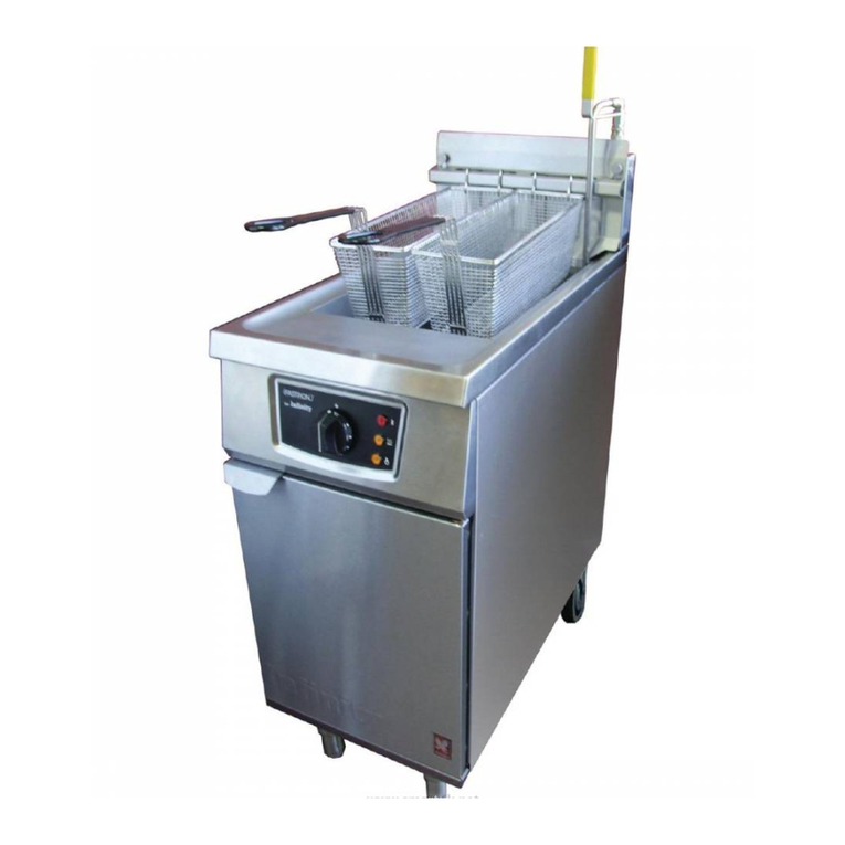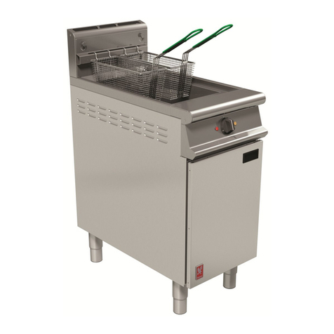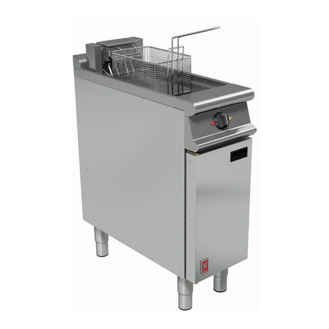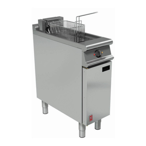
3.2 CONTROL THERMOSTAT
Should this co ponent prove to be faulty, it is not
nor ally repairable. It ust be replaced, using the
following procedure:-
a) Drain pan.
b) Re ove control panel. (Refer to Section 3.1)
c) Identify control ther ostat and re ove push-on
connections. First note their locations.
d) Using a stubby pozidriv screwdriver, re ove
ther ostat fro control panel.
e) Re ove heating ele ent as detailed in Section
3.4.
f) Re ove cover plate on ele ent hinge block
through which capillary tube passes. Manoeuvre
capillary tube and phial through oving hinge tube.
g) Feed capillary tube and phial through hole in base
of hinge block. Re ove ther ostat.
h) Replace ther ostat in reverse order, taking care
that capillary tube is well clear of ele ent
ter inals.
Not
When fitting a new ther ostat, fit existing insulating
sleeving over capillary tubing. Ensure that no tubing
is left exposed to possible contact with live parts.
Coil the excess capillary tube by wrapping it round a
suitable andrel of approxi ately 1
1
/
2
" dia eter.
When fitting gland, ensure it is tightened fir ly but do
not overtighten. Always check fitting for leaks by
re-filling with oil and heating to axi u
te perature.
When fitting ther ostat to control panel, ensure that
earth bonding wire is replaced below one of the
ther ostat fixing lugs. Take care that coiled capillary
tubing is clear of any live parts when control panel is
replaced.
Re-fit the ther ostat in reverse order to re oval.
3.3 PILOT LAMPS - TO REPLACE
a) Re ove control panel. (Refer to Section 3.1)
b) Pull off la p connections.
c) Undo hex nut at rear of la p and re ove la p.
Replace in reverse order.
3.4 HEATING ELEMENT - TO REPLACE
To replace ele ent, proceed as follows:-
a) Drain pan.
b) Re ove basket support bar fro ele ent and fully
raise ele ent.
c) Re ove fixings on underside of ele ent ter inal
box.
d) Re ove ele ent ter inal box cover plate by
prising up lower edge with a screwdriver.
e) Lower ele ent and re ove guard (4 fixings).
f) Re ove ele ent push on connections. First note
their locations.
g) Re ove fixings which secure ele ent to ter inal
box. Re ove ele ent.
Replace in reverse order and ensure that oil
resistant gasket is fitted below ele ent ounting
plate.
Important
Earth bonding connections are provided with
shakeproof or spring washers. It is i portant that
these be correctly replaced during re-asse bly.
3.5 SAFETY THERMOSTAT
3.5.1 To R -s t
In event of control ther ostat failure resulting in
overheating of the oil, the safety ther ostat will
operate and will switch off all power to ele ents.
To re-establish circuit, it will be necessary to re-set
the safety ther ostat.
Allow fryer to cool and re ove control panel (refer to
Section 3.1). This will reveal safety ther ostat which
is ounted on rear of controls co part ent.
To re-set, fir ly press red button.
On double pan odels, LH and RH ther ostats are
appropriate to LH and RH pans respectively.
3.5.2 Saf ty Th rmostat - To R plac
a) Drain pan.
b) Re ove control panel. (Refer to Section 3.1)
c) Identify safety stat and re ove push-on
connections. First note their locations.
d) Using a stubby pozi screwdriver, re ove stat fro
ounting bracket.
e) Re ove heating ele ent as detailed in Section
3.4.
f) Re ove cover plate on ele ent hinge block,
through which capillary tube passes. Manoeuvre
capillary tube and phial through oving hinge
tube.
g) Feed capillary tube and phial through hole in base
of hinge block. Re ove ther ostat.
h) Replace ther ostat in reverse order. Ensure
capillary tube is well clear of ele ent ter inals.
After replacing ther ostat, press red button fir ly to
ensure contacts are in closed condition.
3.7 TILT SWITCH
Located in ele ent re inal box, this should require
no aintenance.
All manuals and user guides at all-guides.com
