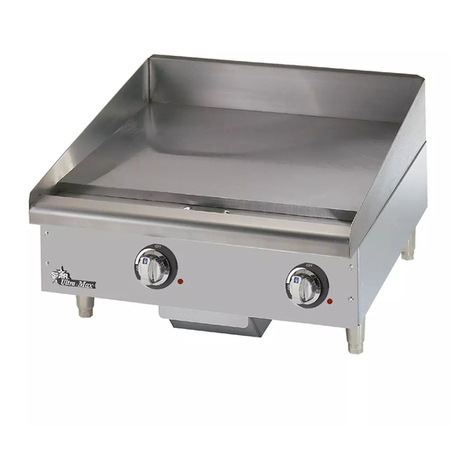
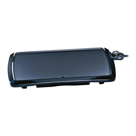
Falcon E350/34 User guide

T100700 Ref. 2
E350/34 and E350/35
GRIDDLE TOPS
INSTALLATION and
SERVICING INSTRUCTIONS
IMPORTANT
The installer must ensure that the installati n f the appliance is in c nf rmity with these instructi ns and
Nati nal Regulati ns in f rce at the time f installati n. Particular attenti n MUST be paid t -
BS7671 IEE Wiring Regu ations
E ectricity at Work Regu ations
Hea th And Safety At Work Act
Fire Precautions Act
This appliance has been CE-marked n the basis f c mpliance with the L w V ltage and EMC Directives f r
the v ltages stated n the Data Plate
WARNING -THIS APPLIANCE MUST BE EARTHED
On c mpleti n f the installati n these instructi ns sh uld be left with the Engineer-in-Charge f r reference
during servicing. Further t this, The Users Instructi ns sh uld be handed ver t the User, having had a
dem nstrati n f the perati n and cleaning f the appliance.
IT IS MOST IMPORTANT THAT THESE INSTRUCTIONS BE CONSULTED BEFORE INSTALLING AND
COMMISSIONING THIS APPLIANCE. FAILURE TO COMPLY WITH THE SPECIFIED PROCEDURES MAY
RESULT IN DAMAGE OR THE NEED FOR A SERVICE CALL.
PREVENTATIVE MAINTENANCE CONTRACT
In rder t btain maximum perf rmance fr m this unit we w uld rec mmend that a Maintenance C ntract be
arranged with
SERVICELINE
. Visits may then be made at agreed intervals t carry ut adjustments and
repairs. A qu tati n will be given up n request t the c ntact numbers bel w.
WEEE Directive Registration No. WEE/DC0059TT/PRO
At end f unit life, disp se f appliance and any replacement parts
in a safe manner, via a licenced waste handler.
Units are designed t be dismantled easily and recycling f all
material is enc uraged whenever practicable.
Fa con Foodservice Equipment
HEAD OFFICE AND WORKS
Wallace View, Hillf ts R ad, Stirling. FK9 5PY. Sc tland.
SERVICELINE CONTACT -
PHONE - 01438 363 000 FAX - 01438 369 900

Warranty Po icy Short ist
Warranty d es n t c ver :-
C rrecting faults caused by inc rrect installati n f a pr duct.
Where an engineer cann t gain access t a site r a pr duct.
Repeat c mmissi n visits.
Replacement f any parts where damage has been caused by misuse.
Engineer waiting time will be chargeable.
R utine maintenance and cleaning.
Gas c nversi ns i.e. Natural t Pr pane gas.
Descaling f water pr ducts and cleaning f water sens rs where s fteners/c nditi ners are n t fitted, r are
fitted and n t maintained.
Bl cked drains.
Independent steam generati n systems.
Gas, water and electrical supply external t unit.
Light bulbs.
Re-installing vacuum in kettle jackets.
Replacement f grill burner ceramics when damage has been clearly caused by misuse.
Where an engineer finds n fault with a pr duct that has been rep rted faulty.
Re-setting r adjustment f therm stats when unit is perating t specificati n.
Cleaning and unbl cking f fryer filter systems due t cust mer misuse.
Lubricati n and adjustment f d r catches.
Cleaning and Maintenance
Cleaning f burner jets
P r c mbusti n caused by lack f cleaning
Lubricati n f m ving parts
Lubricati n f gas c cks
Cleaning/adjustment f pil ts
C rrecti n f gas pressure t appliance.
Renewing f electric cable ends.
Replacement f fuses
C rr si n caused by use f chemical cleaners.

SECTION 1 - INSTALLATION
1.2 SITING
The appliance sh uld be installed n a table, c unter,
r similar surface. Alternatively it can be m unted n
the purp se designed fl r stand supplied by Falc n.
Sh uld it require t be p siti ned in cl se pr ximity t
a wall, partiti n, etc., a minimum clearance f 25mm
at the reae and sides is rec mmended.
A vertical clearance between the the plate and any
verlying c mbustible surface f 900mm sh uld be
all wed. Fire Regulati ns must be c mplied with.
1.3 ELECTRICAL SUPPLY
These units are designed f r use n AC supplies
nly. The E350/34 Griddle plate is f r use n single
phase supplies nly. The E350/35 m del can be used
n single-phase r alternatively n a 2-phase supply.
1.3.1 Supp y Connection
The cable entry is l cated at the rear f the appliance
and is suitable f r 20mm c nduit. A suitable is lating
switch must be pr vided with a minimum c ntact
separati n f 3 mm in all p les. All wiring must be
executed in acc rdance with the regulati ns listed n
the c ver f the manual.
These appliances must be earthed.
A suitable terminal is pr vided f r this purp se and
must be used f r this purp se.
Note
When c nnecting the E350/35, the line terminals
must be c nnected using the link(s) pr vided. See the
diagram bel w.
NL1L2L3
Supply Cables
NL1
1.4 ELECTRICAL RATINGS
The electrical rating is as stated n the unit data plate.
SECTION 2 - ASSEMBLY
a) Rem ve feet fr m bag and screw int l cati ns n
unit base pri r t p siti ning.
b) Place unit in p siti n and carefully level it, using
the feet adjusters if it is t be m unted n a c unter
r table. T m unt unit n purp se built stand, refer
t instructi ns supplied with stand.
c) The appliance is supplied c mplete and ready t
be c nnected t mains supply.
d) T gain access t terminals, pr ceed as f ll ws:-
Rem ve fat drawer(s).
Rem ve tw screws in upper flange f c ntr l panel.
All w panel t dr p d wn slightly t release l wer
fixings. The arms sh uld be swung ut and facia
panel engages up n arms via b tt m trim fixings.
e) The terminals are n w accessible and supply
cables can be fed thr ugh inbuilt c nduit tube.
f) After c nnecting mains supply, replace c ntr l
panel and fat drawer. When fitting c ntr l panel,
present it t l cati n in a dr pped p siti n then
raise it vertically t ensure that l wer fixings are
pr perly engaged. Fit fat drawer. All w h tplate t
heat and check therm stat perates satisfact rily.
g) After c mpleti n f installati n, dem nstrate
meth d f perati n t kitchen staff. P int ut
l cati n f is lating switch f r use in event f an
emergency r during r utine cleaning.
SECTION 3 - SERVICING
BEFORE ATTEMPTING ANY MAINTENANCE,
SWITCH OFF AT THE MAIN (ISOLATING) SWITCH
AND TAKE STEPS TO ENSURE THAT IT IS NOT
INADVERTENTLY SWITCHED ON.
Warning
Since the cast ir n plates are extremely heavy, care
must be exercised when lifting the griddle plate t
carry ut maintenance. The initial lifting p ints are
thr ugh the fat escape h les. A suitable batten f
w d sh uld be inserted between the plate and the
fr nt h b rail t supp rt the weight.
Rest the plate n the batten and take a str ng grip
bel w the fr nt edge f the plate. Raise it t the
desired angle f r access.
Place a suitable w den pr p, capable f supp rting
the weight, bel w the plate. Ensure that it is securely
anch red t prevent accidental slipping. Make sure
als that the appliance base which is much lighter
than the plate cann t m ve whilst lifting the plate.
UNLESS OTHERWISE STATED, PARTS WHICH HAVE BEEN PROTECTED BY THE MANUFACTURER
ARE NOT TO BE ADJUSTED BY THE INSTALLER.
MODEL WIDTH
mm DEPTH
mm HEIGHT
mm WEIGHT
kg WEIGHT
lbs
E350/34 350 650 305 37 82
E350/35 700 650 305 75 166
1.1 MODEL NUMBER, NETT WEIGHTS
and DIMENSIONS

When rdering spares, please qu te the m del
number, serial number and v ltage, as stated n
the data plate.
3.1 CONTROL PANEL - To Remove
Rem ve fat drawer, l cated bel w c ntr l panel.
Rem ve tw fixings in upper flange f facia panel.
All w panel t dr p d wn slightly t release l wer
fixings. Rem ve panel.
Replace in reverse rder.
3.2 THERMOSTAT - To Rep ace
Rem ve c ntr l panel as detailed in Sectu n 3.1.
In c ntr ls c mpartment t p, there are a number f
fixings that secure plate in p siti n, 2 n E350/34 and
4 n E350/35. Rem ve these and raise plate fr m
fr nt. Pr p it up with a suitable piece f w d.
Take care n t t strain therm stat capillary tube.
Und tw fixings that secure therm stat phial
clamping plate and release phial.
Pull ff c nnecti ns t therm stat, n ting l cati ns
acc rding t wire numbers. Pull ff therm stat kn b
and rem ve fixings bel w t release therm stat fr m
panel.
Feed capillary tube and phial f rward thr ugh rear f
c ntr l c mpartment and rem ve assembly.
Replace in reverse rder, taking care t fit insulating
sleeving ver capillary bef re fitting therm stat.
Ensure that earth b nding c nnecti n is replaced
behind therm stat fixing lug. After fitting therm stat,
test unit using a l w setting and check that amber
light g es ut as therm stat pens.
Pull ff c nnecti ns t therm stat, n ting l cati ns.
3.3 PILOT LAMPS - To Rep ace
a) Rem ve c ntr l panel as detailed in Secti n 3.1.
b) Pull ff lamp c nnecti ns.
c) Rem ve nut securing lamp at rear and rem ve
lamp.
3.4. HEATING ELEMENTS - To Rep ace
a) Rem ve c ntr l panel as detailed in Secti n 3.1.
b) Pr p up h tplate as described in Secti n 3.2.
c) Rem ve element c nnecti ns.
d) Rem ve nuts securing element lagging b xes.
e) Rem ve clamping plates securing element.
When fitting a new element, ensure that it is pr perly
fixed t underside f h tplate, l cated by vari us
pr jecti ns cast int plate.
Ensure that element earth c nnecti ns are exactly as
they were bef re replacing element.

E350/35 GRIDDLE PLATE - WIRING DIAGRAM (Drawing No. BW32471/B)
E350/34 GRIDDLE PLATE - WIRING DIAGRAM (Drawing No. AW32470/B)
Other manuals for E350/34
2
This manual suits for next models
1
Other Falcon Griddle manuals

Falcon
Falcon E9541 Manual

Falcon
Falcon G3641 User manual

Falcon
Falcon DOMINATOR PLUS Series User manual

Falcon
Falcon F900 SERIES Manual

Falcon
Falcon G350/7P User guide

Falcon
Falcon E350/35 User guide

Falcon
Falcon G3441 User manual

Falcon
Falcon Dominator Plus E3441 User guide

Falcon
Falcon G350/7 User guide

Falcon
Falcon E350/34 User manual
Popular Griddle manuals by other brands

Cook's Companion
Cook's Companion EASY FLIP PAN Care and use

Vulcan-Hart
Vulcan-Hart VCCG24 Installation & operation manual

Sensio
Sensio Bella 13057 instruction manual

Toastmaster
Toastmaster TMDG24 brochure

CUISIMAT
CUISIMAT PS 400G Instructions for use and installation

Equipex
Equipex SODIR PSE-400 Operation manual