manuals.online logo
Brands
  1. Home
  2. •
  3. Brands
  4. •
  5. Falcon
  6. •
  7. Range
  8. •
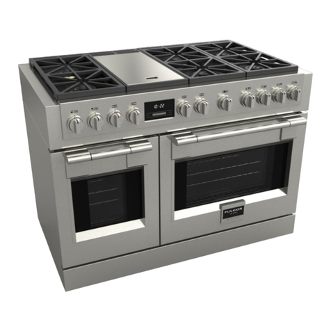
  9. Falcon E350/30 User guide

Falcon E350/30 User guide

T100699 Ref.1
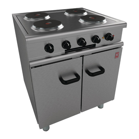
E350/30
FOUR HOTPLATE RANGE
INSTALLATION and
SERVICING INSTRUCTIONS
IMPORTANT
The installer must ensure that the installati n f the appliance is in c nf rmity with these instructi ns and
Nati nal Regulati ns in f rce at the time f installati n. Particular attenti n MUST be paid t -
BS7671 IEE Wiring Regul tions
Electricity t Work Regul tions
He lth And S fety At Work Act
Fire Prec utions Act
This appliance has been CE-marked n the basis f c mpliance with the L w V ltage and EMC Directives f r
the v ltages stated n the Data Plate
WARNING -THIS APPLIANCE MUST BE EARTHED
On c mpleti n f the installati n these instructi ns sh uld be left with the Engineer-in-Charge f r reference
during servicing. Further t this, The Users Instructi ns sh uld be handed ver t the User, having had a
dem nstrati n f the perati n and cleaning f the appliance.
IT IS MOST IMPORTANT THAT THESE INSTRUCTIONS BE CONSULTED BEFORE INSTALLING AND
COMMISSIONING THIS APPLIANCE. FAILURE TO COMPLY WITH THE SPECIFIED PROCEDURES MAY
RESULT IN DAMAGE OR THE NEED FOR A SERVICE CALL.
PREVENTATIVE MAINTENANCE CONTRACT
In rder t btain maximum perf rmance fr m this unit we w uld rec mmend that a maintenance c ntract be
arranged with
AFE SERVICELINE
. Visits may then be made at agreed intervals t carry ut adjustments and
repairs. A qu tati n will be given up n request t c ntact numbers bel w.
WEEE Directive Registr tion No. WEE/DC0059TT/PRO
At end f unit life, disp se f appliance and any replacement parts
in a safe manner, via a licenced waste handler.
Units are designed t be dismantled easily and recycling f all
material is enc uraged whenever practicable.
F lcon Foodservice Equipment
HEAD OFFICE AND WORKS
Wallace View, Hillf ts R ad, Stirling. FK9 5PY. Sc tland.
SERVICELINE CONTACT -
PHONE - 01438 363 000 FAX - 01438 369 900
W rr nty Policy Shortlist
Warranty d es n t c ver :-
C rrecting faults caused by inc rrect installati n f a pr duct.
Where an engineer cann t gain access t a site r a pr duct.
Repeat c mmissi n visits.
Replacement f any parts where damage has been caused by misuse.
Engineer waiting time will be chargeable.
R utine maintenance and cleaning.
Gas c nversi ns i.e. Natural t Pr pane gas.
Descaling f water pr ducts and cleaning f water sens rs where s fteners/c nditi ners are n t fitted,
r are fitted and n t maintained.
Bl cked drains.
Independent steam generati n systems.
Gas, water and electrical supply external t unit.
Light bulbs.
Re-installing vacuum in kettle jackets.
Replacement f grill burner ceramics when damage has been clearly caused by misuse.
Where an engineer finds n fault with a pr duct that has been rep rted faulty.
Re-setting r adjustment f therm stats when unit is perating t specificati n.
Cleaning and unbl cking f fryer filter systems due t cust mer misuse.
Lubricati n and adjustment f d r catches.
Cleaning and Maintenance:
Cleaning f burner jets
P r c mbusti n caused by lack f cleaning
Lubricati n f m ving parts
Lubricati n f gas c cks
Cleaning/adjustment f pil ts
C rrecti n f gas pressure t appliance.
Renewing f electric cable ends
Replacement f fuses
C rr si n caused by use f chemical cleaners.
SECTION 1 - INSTALLATION
1.2 SITING
The appliance sh uld be installed n a firm level fl r
in a well lit p siti n. Sh uld the unit be required t be
p siti ned in cl se pr ximity t a wall, partiti n r
dec rative finish, etc. the surface must be
c nstructed f n n-c mbustible material.
Alternatively it may be clad in a suitable
n n-c mbustible insulating material. Cl se attenti n
sh uld be paid t Fire Regulati ns.
1.3 ELECTRICAL SUPPLY
The appliance is designed f r use n AC supplies
nly and can be perated n either a 3 phase/4 wire
AC supply r a single phase AC supply by using the
bridging links supplied.
W rning
This appliance must be earthed. (An earth terminal is
pr vided).
The c nnecti n t the mains electric supply must be
made thr ugh a suitable is lating switch with a
c ntact separati n f at least 3mm in all p les.
Wiring sh uld c nf rm t I.E.E. regulati ns and the
installati n sh uld satisfy the l cal supply auth rity.
1.4 ELECTRICAL RATINGS
The electrical rating is as stated n unit data plate.
Note
The h tplates emb dy a temperature limiting device.
This aut matically cuts ff part f the element circuit
sh uld the plate bec me verheated due t being left
switched n with ut a p t n it.
SECTION 2 - ASSEMBLY
a) Place appliance in p siti n and carefully level by
turning feet adjusters. H les are pr vided t enable
the unit t be fixed t fl r if c nsidered necessary.
b) Open d r and rem ve all packing material etc.
c) C nnect unit t electrical supply (terminals
underneath).
Note
If a single phase AC supply is being used, fit the
bridging links supplied and c nnect t the mains
strictly in acc rdance with Figure 1.
NL1L2L3
Supply Cables
NL1
d) Switch appliance n. Ensure that all c ntr ls,
elements and pil t lamps functi n c rrectly.
e) After c mpleti n f installati n, dem nstrate
meth d f perati n t kitchen staff. P int ut
l cati n f mains is lating switch t be shut d wn
in event f an emergency r during cleaning.
SECTION 3 - SERVICING
BEFORE ATTEMPTING ANY SERVICING ISOLATE
THE APPLIANCE AT THE MAIN SWITCH AND
TAKE STEPS TO ENSURE IT IS NOT
INADVERTENTLY SWITCHED ON.
When rdering spares please qu te the m del
number, serial number and v ltage as stated n the
data plate, l cated bel w ven base plate.
3.1 CONTROL PANEL - TO REMOVE
Rem ve fixings in upper flange f panel (bel w fr nt
f h b). Ease t p f panel f rward slightly and lift it up
t release panel.
3.2 THERMOSTAT - TO REMOVE
a) Rem ve c ntr l panel as detailed in Secti n 3.1.
b) Und tw nuts inside plated side trim ends.
c) Pull h tplate assembly f rward t release fr nt
fixing and swing it up, piv ting at the rear. Pr p
plate up in raised p siti n.
d) Open d r and release therm stat phial fr m ven
r f clips.
e) Feed capillary tube up thr ugh h le in ven r f
and thr ugh h le in c ntr ls c mpartment.
f) Rem ve c nnecti ns t therm stat then pull ff
kn b.
Rem ve screws which secure therm stat t c ntr l
panel. Rem ve therm stat.
When fitting a new therm stat, fit existing insulating
sleeving ver capillary tube.
Av id kinking capillary tubing and ensure earth
c nnecti n is replaced.
UNLESS OTHERWISE STATED, PARTS WHICH HAVE BEEN PROTECTED BY THE MANUFACTURER
ARE NOT TO BE ADJUSTED BY THE INSTALLER
MODEL WIDTH
mm DEPTH
mm HEIGHT
mm WEIGHT
kg WEIGHT
lbs
E350/30 700 650 870 91 201
1.1 MODEL NUMBER, NETT WEIGHTS
nd DIMENSIONS
3.3 HOTPLATES - TO REMOVE
a) Rem ve facia panel as detailed in Secti n 3.1 and
raise h tplate assembly as detailed in Secti n 3.2.
b) Rem ve h tplate c nnecti ns and und central
fixing nut. This will all w h tplate t be rem ved
fr m t p.
Fit replacement plate in reverse rder, referring t
wiring diagram when re-c nnecting.
3.4 CONTROL SWITCHES - TO REMOVE
a) Rem ve c ntr l panel as detailed in Secti n 3.1.
b)Rem ve switch c nnecti ns, n te cable
arrangement.
c) Pull ff c ntr l kn b and und fixing screws t
release switch. Fit new switch in reverse rder,
ensure that earth b nding wire is attached t it.
3.5 PILOT LAMPS - TO REMOVE
a) Rem ve c ntr l panel as detailed in Secti n 3.1.
b) Pull ff c nnecti ns t lamp.
c) Rem ve nut at panel rear t release lamp. Fit
replacement in reverse rder.
3.6 OVEN ELEMENTS - TO REMOVE
a) Rem ve c ntr l panel as detailed in Secti n 3.1.
b) Rem ve uter side panels as f ll ws. Und
screws in rear flange f panel. Swing panel rear
utward slightly then f rward t release fr nt fixing.
c) Open d r and rem ve base panel.
d) Rem ve element c nnecti ns and und fixing nut.
e) Withdraw element fr m inside ven. Replace
element in reverse rder, ensuring small earth
b nding wire c nnecti n is securely fastened in
place.
4
3
1
2
5
P2
P1
P3
4
3
1
2
5
P2
P1
P3
4
3
1
2
5
P2
P1
P3
4
3
1
2
5
P2
P1
P3
E350/30 RANGE - WIRING DIAGRAM

Other manuals for E350/30

3

Other Falcon Range manuals

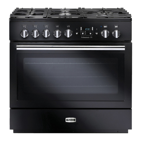
Falcon Classic 110 Dual Fuel Instruction Manual

Falcon

Falcon Classic 110 Dual Fuel Instruction Manual

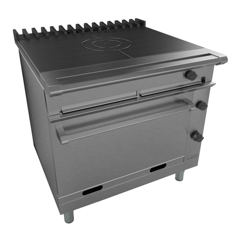
Falcon Dominator Plus User guide

Falcon

Falcon Dominator Plus User guide

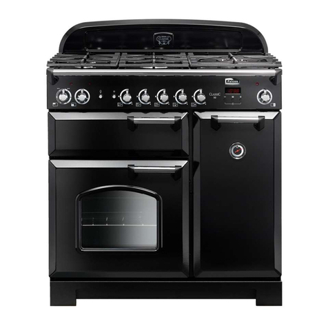
Falcon Classic Deluxe Instruction Manual

Falcon

Falcon Classic Deluxe Instruction Manual

Falcon Generic 110 Ceramic Instruction Manual

Falcon

Falcon Generic 110 Ceramic Instruction Manual

Falcon Professional 90 Fuel Instruction Manual

Falcon

Falcon Professional 90 Fuel Instruction Manual

Falcon G350/1 User manual

Falcon

Falcon G350/1 User manual

Falcon Nexus 110 Induction Instruction Manual

Falcon

Falcon Nexus 110 Induction Instruction Manual

Falcon Classic Deluxe 100 Dual Fuel Instruction Manual

Falcon

Falcon Classic Deluxe 100 Dual Fuel Instruction Manual

Falcon Classic 110 Dual Fuel Instruction Manual

Falcon

Falcon Classic 110 Dual Fuel Instruction Manual

Falcon Elan 90 Ceramic Operation manual

Falcon

Falcon Elan 90 Ceramic Operation manual

Falcon Classic 90 Gas Operation manual

Falcon

Falcon Classic 90 Gas Operation manual

Falcon G350/1 User guide

Falcon

Falcon G350/1 User guide

Falcon Elise 110 Dual Fuel Instruction Manual

Falcon

Falcon Elise 110 Dual Fuel Instruction Manual

Falcon Dominator Plus E3101P/D User manual

Falcon

Falcon Dominator Plus E3101P/D User manual

Falcon G1006BX Installation instructions

Falcon

Falcon G1006BX Installation instructions

Falcon Dominator Plus G3101 Quick guide

Falcon

Falcon Dominator Plus G3101 Quick guide

Falcon Dominator Series User manual

Falcon

Falcon Dominator Series User manual

Falcon 1000 Mercury Dual Fuel Instruction Manual

Falcon

Falcon 1000 Mercury Dual Fuel Instruction Manual

Falcon 900S Dual Fuel User manual

Falcon

Falcon 900S Dual Fuel User manual

Falcon E350/30 User manual

Falcon

Falcon E350/30 User manual

Falcon Classic 90 Gas Instruction Manual

Falcon

Falcon Classic 90 Gas Instruction Manual

Falcon U110138 - 03 Instruction Manual

Falcon

Falcon U110138 - 03 Instruction Manual

Falcon 211 EEO Ceramic User guide

Falcon

Falcon 211 EEO Ceramic User guide

Falcon Hi-LITE 110 Instruction Manual

Falcon

Falcon Hi-LITE 110 Instruction Manual

Popular Range manuals by other brands

Jenn-Air JES8850CAF00 Use & care guide

Jenn-Air

Jenn-Air JES8850CAF00 Use & care guide

Indesit K 342 G/R Installation & use

Indesit

Indesit K 342 G/R Installation & use

Greystone CF-RV17 instruction manual

Greystone

Greystone CF-RV17 instruction manual

Bosch HES3052U-01 use and care manual

Bosch

Bosch HES3052U-01 use and care manual

Frigidaire FGFB33WHSA owner's guide

Frigidaire

Frigidaire FGFB33WHSA owner's guide

Amana ACR3130BAW User instructions

Amana

Amana ACR3130BAW User instructions

Metos Proxy Series manual

Metos

Metos Proxy Series manual

Toastmaster RH36D4 Specifications

Toastmaster

Toastmaster RH36D4 Specifications

GE JBS03 owner's manual

GE

GE JBS03 owner's manual

GE EER 3001 owner's manual

GE

GE EER 3001 owner's manual

Frigidaire FPGF3685LSA installation instructions

Frigidaire

Frigidaire FPGF3685LSA installation instructions

Dacor Renaissance RNRP36GSNGH use and care manual

Dacor

Dacor Renaissance RNRP36GSNGH use and care manual

Frigidaire CGEF3030PWA installation instructions

Frigidaire

Frigidaire CGEF3030PWA installation instructions

GE PB975SPSS - Profile 30" Electric Ran Dimensions and installation information

GE

GE PB975SPSS - Profile 30" Electric Ran Dimensions and installation information

Maytag MGR4451BDS - 30 Inch Gas Range Use and care guide

Maytag

Maytag MGR4451BDS - 30 Inch Gas Range Use and care guide

Maytag 8101P407-60 installation manual

Maytag

Maytag 8101P407-60 installation manual

Frigidaire 18" built-in and portable use & care

Frigidaire

Frigidaire 18" built-in and portable use & care

Maytag MES5552BAB - 30 Inch Slide-In Electric Range Dimensions

Maytag

Maytag MES5552BAB - 30 Inch Slide-In Electric Range Dimensions

manuals.online logo
manuals.online logoBrands
  • About & Mission
  • Contact us
  • Privacy Policy
  • Terms and Conditions

Copyright 2025 Manuals.Online. All Rights Reserved.