SECTION 1 - GENERAL DESCRIPTION
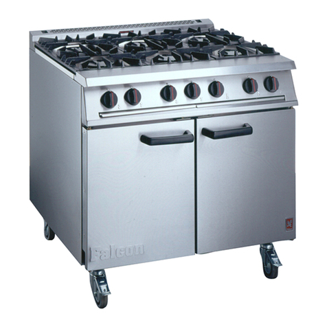
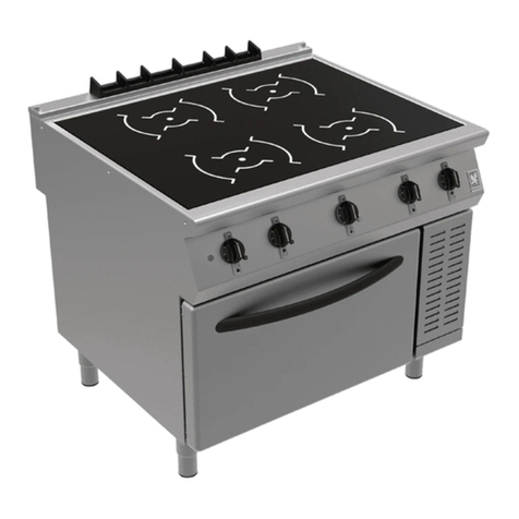
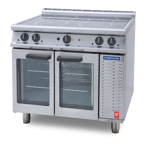
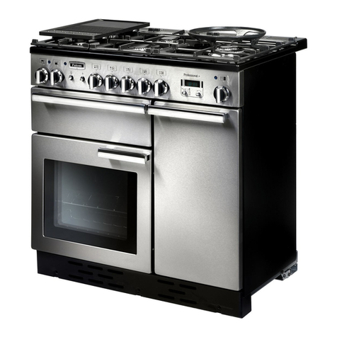
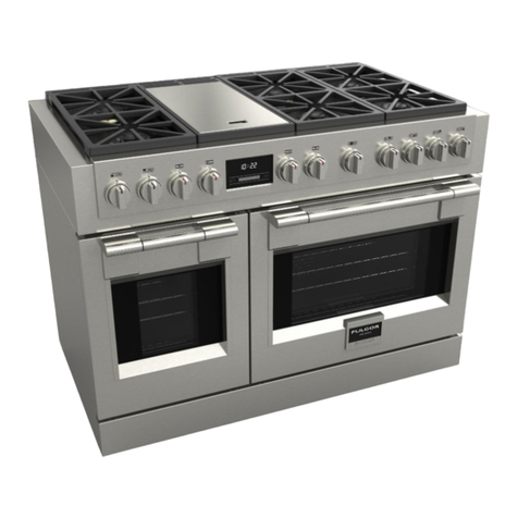
The 350/1 open-top range and G350/2 solid-top
range are two floor standing ranges in the Falcon
350 series. All individual units co prising the Series
are of odular di ensions, enabling suites of
appliances to be installed in a atching line. So e
units are for "counter" ounting, eaning that they
can be installed either on a table or si ilar, or
alternatively on purpose- ade stands, supplied by
Falcon, which ensure perfect atching of hob- height
when installed with floor-standing appliances such as
the ranges.
The G350/1 is a range with 4 open-top burners each
4.3kW(14,700 Btu/hr) heat rating, controlled by safety
taps.
The oven, fitted two doors, is heated by a
ther ostatically controlled burner of 4.75kW
(16,200 Btu/hr), protected by a fla e failure device
and equipped with push-button ignition.
The oven has a no inal volu e of approxi ately
0.09
3
(3.26ft
3
) and is supplied with two wire
grid shelves. Five shelf positions are provided.
The G350/2 solid top range has an oven identical to
the G350/1 , but has a heavy-duty solid-top. The solid
top consists of the traditional centre ring and side
fillings and is heated by a single burner of 7.7kW
(26,800 Btu/hr) capacity. It is controlled by a
co bined on/off tap and fla e-failure device, ignition
of the burner being by a anually-lit pilot. The tap has
indented positions for full fla e and "si er".
Open Top Taps
Oven Control
(Ther ostat)
Spark Igniter Fla e Failure
Button (in Front Button (in Front
Fra e behind Fra e behind
LH Door) RH Door)
Figure 1 - Open Top Range
Solid Top Control
(Ther ostat)
Oven Control
(Ther ostat)
Spark Igniter Fla e Failure
Button (in Front Button (in Front
Fra e behind Fra e behind
LH Door) RH Door)
Figure 2 - So id Top Range
SECTION 2 - LIGHTING and OPERATIONS
2.1 Open Top
All four burners are equally rated and ay be used for
fast boiling or si ering. The pan supports, which
are interchangeable, will safely acco odate pans
fro 125 dia eter upwards.
The gas taps are of the safety type and include a
fla e failure device.
To Light The Burner
Identify appropriate tap by observing the facia panel
arker . Push the tap knobs inwards then turn fully
anti-clockwise to the FULL FLAME setting and hold
the control knob in for approxi ately 20 seconds
whilst applying a lit atch or taper to burner head ri .
The knob can then be turned anti-clockwise to reduce
fla e, if desired.
To Turn The Burner OFF
Si ply turn knob clockwise as far as it will go
(see Figure 3).
OFF FULL ON SIMMER
(turn anti-clockwise) (turn further
anti-clockwise)
Figure 3
2.2 So id Top
Warning
If pilot is extinguished intentionally or unintentionally,
no atte pt to re-light the gas should be ade until at
least 3 inutes have elapsed.
The procedures are as follows -
Lighting The Burner (Refer to Figure 4)
1. Re ove solid-top centre ring using special tool
provided.
2. Have a lit taper or atch ready in one hand.
3. With other hand, push in control knob and turn it
anti-clockwise until ark on knob is opposite
ignition sy bol.
4. Apply light to pilot, still keeping knob pushed in.
5. After about 20 seconds, release knob, pilot should
re ain alight. If not, push in control knob and turn
clockwise to OFF position. Wait 3 inutes, then
repeat fro step 2.
6. With pilot fla e established, replace solid top
centre ring.
7. Push knob in again and turn it anti-clockwise to
FULL FLAME sy bol thus lighting burner.
