manuals.online logo
Brands
  1. Home
  2. •
  3. Brands
  4. •
  5. Falcon
  6. •
  7. Security System
  8. •
  9. Falcon 25 Series User manual

Falcon 25 Series User manual

*47344937*
47344937
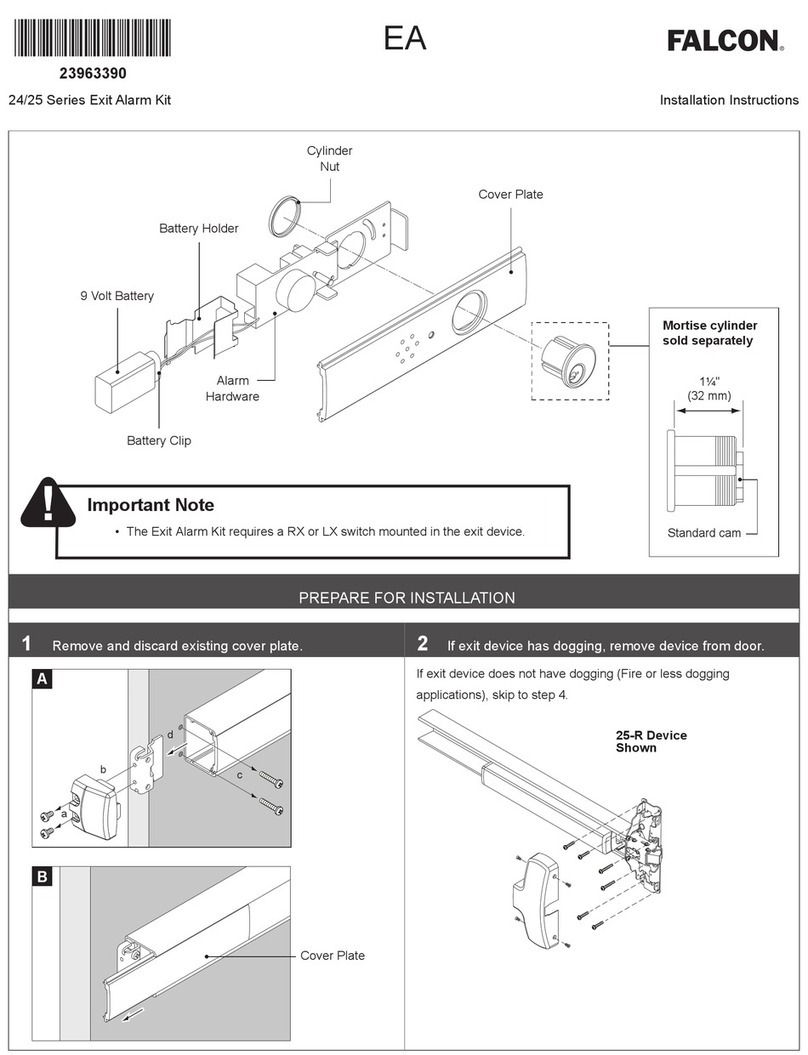
PREPARE FOR INSTALLATION
1 Remove and discard existing cover plate.
a
bc
d
A
B
Cover Plate
2 If exit device has dogging, remove device from door.
If exit device does not have dogging (Fire or less dogging
applications), skip to step 4.
25-R Device
Shown
24/25 Series
Exit Alarm (EA) Kit Installation Instructions
Mortise cylinder
with straight cam
sold separately
1¹⁄₄"
(32 mm)
Standard cam
9 Volt Battery
Cylinder Nut
Battery Clip
Cover Plate
Alarm Hardware
Battery
Holder
Remove
and discard
Important Note: The Exit Alarm Kit requires a RX or LM/DM switch mounted in the exit device.
3 Remove and discard dogging assembly.
Dogging assemblies are shown below.
a
b
c
4 Cut new cover plate as needed to match exit device
length.
Cover plate
should be flush
with end of
mechanism case.
Important: Cut end of
cover plate nearest
the push bar.
ASSEMBLE AND INSTALL
5 Assemble the exit alarm unit with the parts in order as
shown below.
Ensure cylinder nut is adequately
tightened down. A loose cylinder
nut can result in inconsistent
switch actuation.
Cylinder nut
Cam should be in
OFF position before
battery is installed
or power is connected
6 If exit device does not have LM/DM or RX switch, install
switch before proceeding.
LNote: Refer to the appropriate LM/DM or RX installation
instructions.Attach wiring to terminal blocks on exit alarm
7 Attach wiring to terminal blocks on exit alarm kit board as shown.
LNotes about Wiring:
The EI (external inhibit) option uses NO (normally open) dry contacts to inhibit the exit alarm.
Closing the access control contacts inhibits the exit alarm. When the access control contacts are re-opened, the exit alarm re-arms with no
delay.
RX, LM, DM, and EI inputs are not polarized.
OR *
Gray
Black
Violet
(Optional)
Von Duprin Power Supply (PS902)
RX Switch * Insulate unused wire
(Optional)
EI -NO
(normally open
access control
dry contacts)
NC
C
NO
24 VDC
9V Battery
Connector
EPT-10 or Electric Hinge
White
*
LM/DM Switch Insulate unused
wire
*LM uses White/Violet
*DM uses White/Gray
GND
RX/LM/DM
GND
EXT IN
GND
24 VDC
1
2
GND
RX/LM/DM
S2
.
2
8 Adjust alarm reset time, as needed.
Adjust dip switches as shown below to adjust reset time.
LAuto Reset Time (minutes): Amount of time alarm will sound
before resetting automatically (no manual intervention).
S2-2 S2-1 Reset
OFF OFF NONE
ON OFF 1.5
OFF ON 3
ON ON 4.5
9 Partially install new cover plate.
10 Connect battery and slide into holder.
Make sure
polarity
is correct
Back side of
cover plate shown
a
b
11 Reinstall exit device onto door as needed.
12 Reinstall end cap bracket.
13 Install end cap.
14 Install decal on exit device pushbar.
EMERGENCY EXIT
PUSH TO OPEN
ALARM
WILL SOUND
3
© Allegion 2021
Printed in U.S.A.
47344937 Rev. 09/21-b
Changing the Battery
If the battery is low, a beep will sound and the LED will ash every
10 to 15 seconds until the battery is changed. The low battery alarm
can be stopped by disarming the unit.
To change the battery, follow steps
A
through
D
below, then
reassemble.
Remove end cap
Slide out EA assembly far enough to reach battery
Make sure
polarity
is correct
c
d
a
b
Change battery
Slide into holder
Operating Instructions
1 Insert the key into the cylinder and arm the unit by
turning the key clockwise to position B until it stops.
Return key to position A to remove.
LNote: There is a 15 to 20 second delay before arming during
which the LED will ash every 3 to 5 seconds.
B
A
RHR Shown
(LHR opposite)
TO ARM
2 Observe the LED.
After the 15-20 second delay has passed, the horn will sound briey
and the LED will ash every 12 to 15 seconds. This indicates that
the exit alarm kit is now in armed mode.
3 Turn the key counterclockwise to position C to disarm.
A
C
RHR Shown
(LHR opposite)
TO DISARM
Push to test
Customer Service
1-877-671-7011 www.allegion.com/us

Other manuals for 25 Series

1

This manual suits for next models

1

Other Falcon Security System manuals

Falcon 7 inch Wireless Camera System User manual

Falcon

Falcon 7 inch Wireless Camera System User manual

Falcon TBM-18 User manual

Falcon

Falcon TBM-18 User manual

Falcon PREDATOR EVO3 User manual

Falcon

Falcon PREDATOR EVO3 User manual

Falcon PREDATOR MKIII Quick start guide

Falcon

Falcon PREDATOR MKIII Quick start guide

Falcon MEL 24 Series User manual

Falcon

Falcon MEL 24 Series User manual

Falcon 25 Series User manual

Falcon

Falcon 25 Series User manual

Popular Security System manuals by other brands

SMS Senator 2 installation manual

SMS

SMS Senator 2 installation manual

Trailer Vision Digi-Max2 Installation and user manual

Trailer Vision

Trailer Vision Digi-Max2 Installation and user manual

Amcrest AL-HUB1 quick start guide

Amcrest

Amcrest AL-HUB1 quick start guide

Frontpoint Security System quick start guide

Frontpoint

Frontpoint Security System quick start guide

AlphaVision ML user manual

AlphaVision

AlphaVision ML user manual

Spamel OP1-W01-A-11 quick start guide

Spamel

Spamel OP1-W01-A-11 quick start guide

WiLife V2.0 Release notes

WiLife

WiLife V2.0 Release notes

Daewoo WOS301 Quick installation guide

Daewoo

Daewoo WOS301 Quick installation guide

ADEMCO VIA-30PSE quick guide

ADEMCO

ADEMCO VIA-30PSE quick guide

LuxHome HomeSys Installation and operating instructions

LuxHome

LuxHome HomeSys Installation and operating instructions

Lorex LHB806 Quick connection guide

Lorex

Lorex LHB806 Quick connection guide

Geemarc SOS-PRO 295 user manual

Geemarc

Geemarc SOS-PRO 295 user manual

GE 600-1064-95R b installation guide

GE

GE 600-1064-95R b installation guide

Kidde KN-COB-DP-H) manual

Kidde

Kidde KN-COB-DP-H) manual

Risco Agility user manual

Risco

Risco Agility user manual

Ideal Security SK634 instruction manual

Ideal Security

Ideal Security SK634 instruction manual

Robotics Technologies Bus-Scan ALERT Installation & operation manual

Robotics Technologies

Robotics Technologies Bus-Scan ALERT Installation & operation manual

Ksenia imago KSI6300000.3 Series Quick installation guide

Ksenia

Ksenia imago KSI6300000.3 Series Quick installation guide

manuals.online logo
manuals.online logoBrands
  • About & Mission
  • Contact us
  • Privacy Policy
  • Terms and Conditions

Copyright 2025 Manuals.Online. All Rights Reserved.