Fancom IM.60 24V + CPS User manual

G N
Gn

N.B.: The original, authentic version of this manual is the English version produced by Fancom B.V. or one of its
daughter companies (referred to further as Fancom). Any modifications introduced to this manual by third parties
have neither been checked nor approved by Fancom. Modifications are taken by Fancom to include translations
into languages other than English and the insertion and/or deletion of text and/or illustrations to/from the original
contents. Fancom cannot be held liable for any damages, injury, guarantee claims and other claims relating to this
type of modification, in as far as these modifications result in a content that differs from the original English
version of this manual produced by Fancom. For the latest information about product installation and operation,
please contact the customer service dept. and/or the technical service dept. of the Fancom concerned. In spite of
the care taken when compiling this manual, if you should discover any errors, please inform Fancom B.V. in
writing. Fancom B.V., PO Box 7131, 5980 AC Panningen (the Netherlands).
Copyright © 2019 Fancom B.V.
Panningen (the Netherlands)
All rights reserved. Nothing from this manual may be copied, distributed or translated into other languages, partly
or wholly, without express prior written permission from Fancom. Fancom reserves the right to modify this manual
without notice. Fancom can give no guarantee, neither implicit nor explicit, for this manual. All risks are for the
user.
This manual has been compiled with the utmost care. If, however, you should discover an error, please inform
Fancom B.V.
Art.Nr. 5911920
GB190903

Gn
i
g
1. General introduction .................................................................................................................................. 1
1.1 Fancom Sales & Service Center..................................................................................................... 1
1.2 How to use this manual .................................................................................................................. 1
1.3 Safety instructions and warnings.................................................................................................... 2
2. Installing the iM.60...................................................................................................................................... 3
2.1 Mount the iM.60.............................................................................................................................. 3
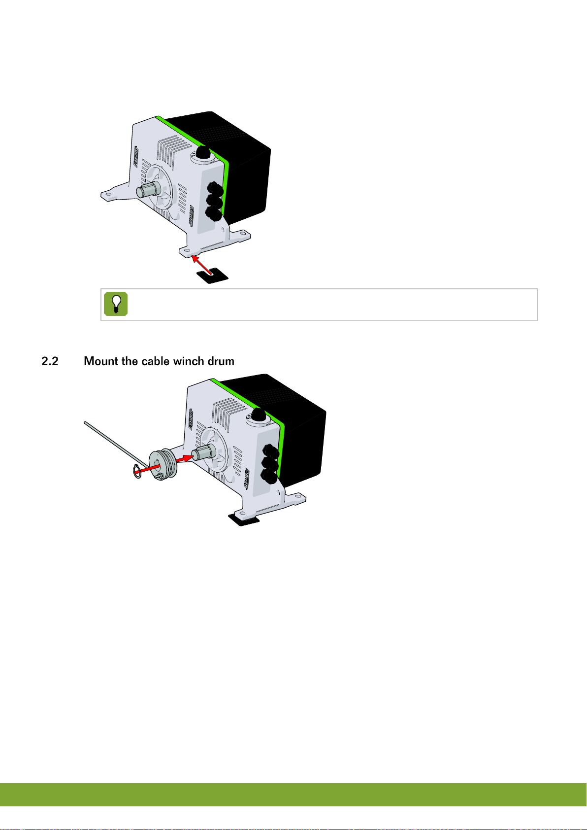
2.2 Mount the cable winch drum........................................................................................................... 4
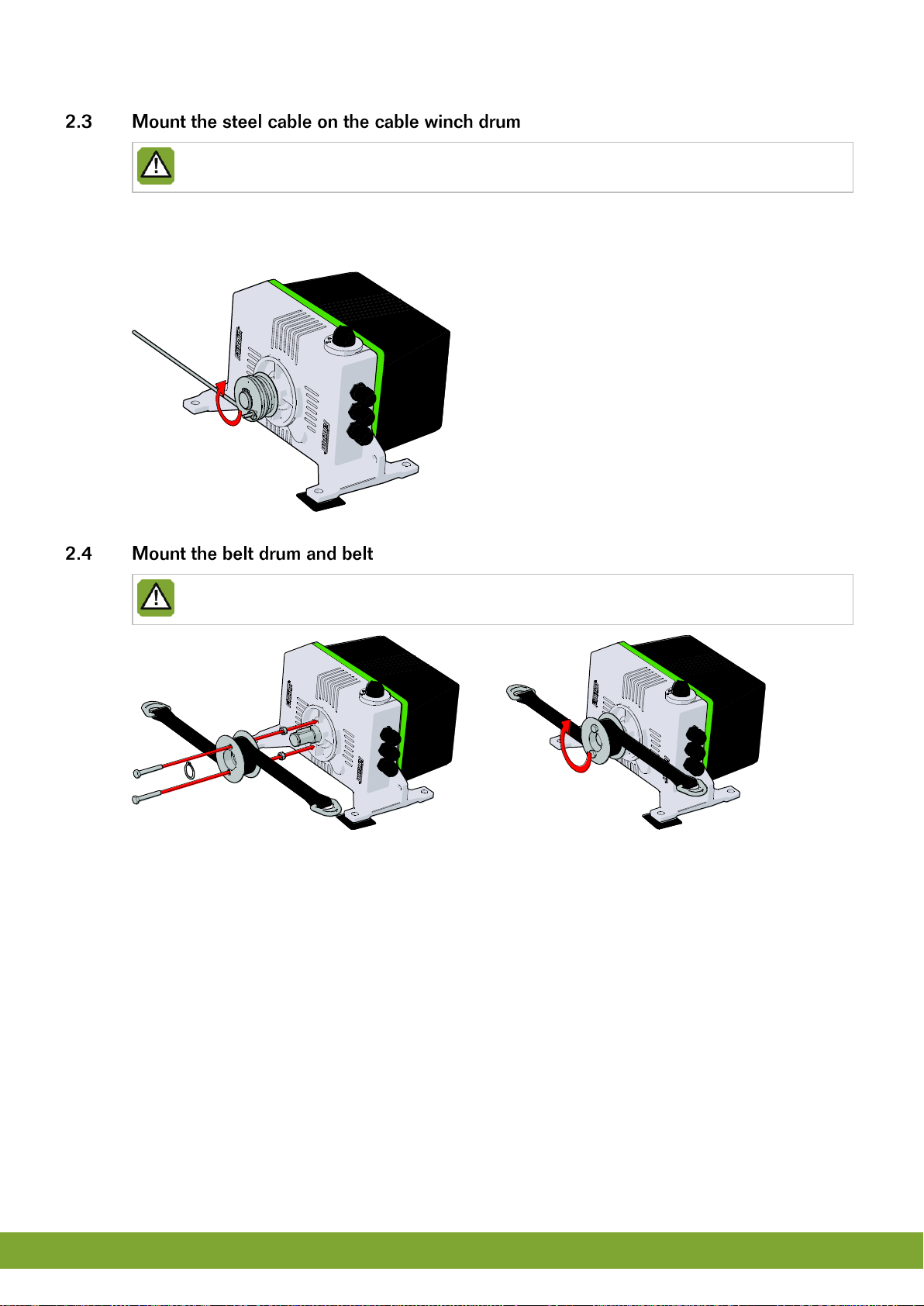
2.3 Mount the steel cable on the cable winch drum.............................................................................. 5
2.4 Mount the belt drum and belt.......................................................................................................... 5
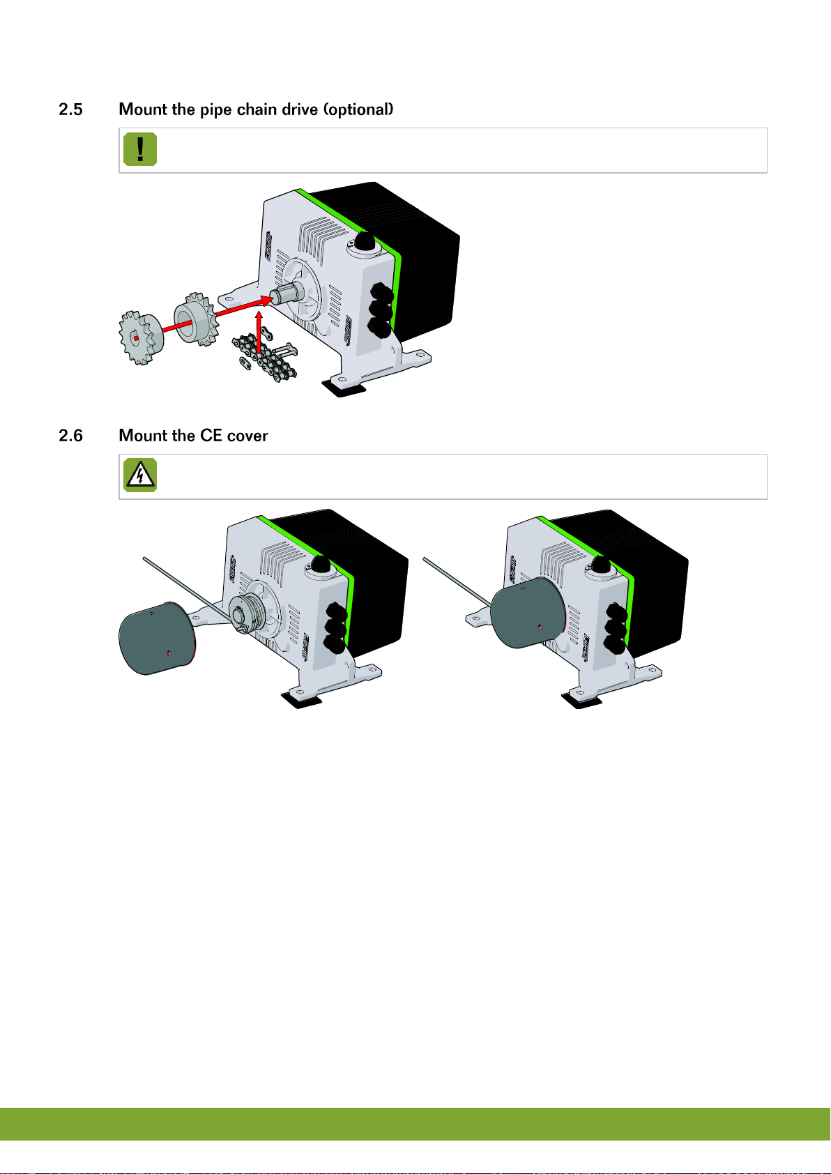
2.5 Mount the pipe chain drive (optional).............................................................................................. 6
2.6 Mount the CE cover........................................................................................................................ 6
2.7 Mount the CE protection cover on the belt drum ............................................................................ 7
2.8 Connect the iM.60 .......................................................................................................................... 7
2.9 Test the iM.60............................................................................................................................... 10
3. Using the iM.60 ......................................................................................................................................... 11
3.1 Set the switch............................................................................................................................... 11
3.2 Remote manual operation ............................................................................................................ 11
3.3 Disposal / recycling....................................................................................................................... 11
4. Adjusting the iM.60................................................................................................................................... 12
4.1 Adjust limit switches ..................................................................................................................... 14
4.2 Adjust the CLOSE position........................................................................................................... 16
4.3 Adjust the OPEN position (if CLOSE already is adjusted)............................................................ 17
4.4 Adjust the PREDEFINED position ................................................................................................ 17
4.5 Complete adjustments.................................................................................................................. 17
5. Extra possibilities..................................................................................................................................... 18
5.1 Using the emergency battery (optional)........................................................................................ 18
5.2 Predefined position / adjusting independently .............................................................................. 18
5.3 Reversing the direction of rotation................................................................................................ 19
5.4 Maximum thermostat (optional).................................................................................................... 19
5.5 External alarm led (optional)......................................................................................................... 20
5.6 Fantura air inlet............................................................................................................................. 20
5.7 Restore factory settings................................................................................................................ 20
6. Alarms ....................................................................................................................................................... 21
7. Technical specifications .......................................................................................................................... 22
8. Appendix: connection diagram............................................................................................................... 24
9. EC declaration of conformity................................................................................................................... 25

Gn
1
g
This manual has been created with the utmost care. If, however, you should discover an error, please inform
Fancom B.V.
For any questions and support, please contact the local Fancom Sales & Service Center.
The following symbols are used in this manual:
Tips and suggestions.
Note providing recommendations and additional information.
Warning indicating damage to the product if you do not follow procedures carefully.
Warning indicating danger to humans or animals.
Electric shock hazard. Danger to humans and animals.
Example of a practical application of the described functionality.
Calculation example.

Gn
2
g
Before installing and commissioning the iM.60, read the safety instructions, provisions and conditions carefully.
This paragraph contains a number of general safety instructions. The installation of the device and remedying of
any malfunctions should be performed by a certified electrical installer according to the applicable norms. The
guarantee does not apply if this product is installed in any other way than is indicated by Fancom and if the
product's motor has been opened and changes have been made to the product.
Disconnect power before installation.
Prevent electrostatic discharge (ESD) when working on the iM.60. Ensure that the workplace is clean
and dry.
Use correct wires as shown in the connection diagrams.
Make all wiring connections and check them before applying power. Incorrect connections can cause
permanent damage.
Never place the iM.60 in a place where the weather has direct influence (not in the sun, not in places
where the temperature can rise sharply etc.).
Inspect the iM.60 periodically for any damages. Notify your installation technician immediately of any
damages. A damaged iM.60 is unsafe!
It is advisable not to switch off the iM.60. This could lead to condensation caused by cooling down.
Do not touch any of the iM.60 moving parts.

Gn
3
g
Install the iM.60 and associated components as follows:
1. Place the iM.60 (see page 3)
2. Mount the coercion roller (see page 4)
3. Mount the steel cable on the cable winch drum(see page 4)
4. Mount the belt drum and belt (see page 5)
5. Mount the pipe chain drive (optional) (see page 5)
6. Mount the CE cover (see page 6)
7. Connect the iM.60 (see page 7)
8. Test the iM.60 (see page 10)
Never place the iM.60 in a place where the weather has direct influence (not in the sun, not in places
where the temperature can rise sharply etc.).
Place the iM.60 only inside the house.
Place the iM.60 at such a height that the manual control can be used.
Do not place the iM.60 with the driveshaft pointing upwards. This keeps water from entering the motor
via the drive shaft. If you do place the iM.60 with the driveshaft pointing upwards, then mount the CE
cover on the shaft.
Cable / pulley combination

Gn
4
g
1. Drill holes in the floor surface. For this, you can use the included drill template. Ensure at least 130 mm of
free space behind the iM.60. This is the space required to disassemble the cover.
2. Place the iM.60 on a flat subsurface with the screw fittings on the bottom.
If the iM.60 cannot be placed on a flat subsurface, you can use the included shims (0.5 mm and
1.0 mm thickness).
3. Seal the screw fittings with grout to prevent penetration of moisture, dust and/or corrosive gases.

Gn
5
g
Ensure that you have the steel cable on the correct side and that you have the proper direction of
rotation for coiling up the steel cable.
1. Pull the steel cable through the hole in the flange.
2. Mount the retaining clip on the end of the steel cable.
3. Wrap the steel cable around the flange at least once.
Ensure that you have the belt on the correct side and that you have the proper direction of rotation for
coiling up the belt.

Gn
6
g
The chain drive is suitable for 1-inch pipe.
Placement of the CE cover is mandatory if the iM.60 is installed within reach (lower than 2.5 m above
the subsurface) of humans or animals.

Gn
7
g
Placement of the CE cover is mandatory if the iM.60 is installed within reach (lower than 2.5 m above
the subsurface) of humans or animals.
You may connect to the iM.60 as an I/O network module or as a traditional terminal.
Install the cables in such a way that they cannot become damaged and so that they can easily be
replaced in the event of malfunction. Limit the length of the cables much as possible.
Low-voltage and high-voltage wires may not be placed parallel to each other but may cross each other.
When using metal cable trays, Fancom advises to connect the cable trays to protective earth at the
ends and at as many other places as possible.
When using two iM.60, connect both iM.60 to one Fancom double insulated transformer 230V/24Vac
100VA (35431003).

Gn
8
g
Set the I/O address
Using the table below, set the I/O address with the dipswitches 1 thru 5.
In an I/O network, all iM.60 units must have a unique address.
I/O
address
DIP 1
DIP 2
DIP 3
DIP 4
DIP 5
DIP 6
DIP 7
DIP 8
DIP 9
DIP 10
AN.
ON
ON
ON
ON
ON
ON =
iM.60
doesn’t
measure
the
temperatu
re itself
OFF =
iM.60
measures
the
temperatu
re itself
ON = Not
using
batteries
OFF =
Using
batteries
ON =
Default
direction
of
rotation
OFF =
Inverse
direction
of
rotation
ON =
CPS
OFF =
Potentiom
eter
Not used
1
OFF
ON
ON
ON
ON
2
ON
OFF
ON
ON
ON
3
OFF
OFF
ON
ON
ON
4
ON
ON
OFF
ON
ON
5
OFF
ON
OFF
ON
ON
6
ON
OFF
OFF
ON
ON
7
OFF
OFF
OFF
ON
ON
8
ON
ON
ON
OFF
ON
9
OFF
ON
ON
OFF
ON
10
ON
OFF
ON
OFF
ON
11
OFF
OFF
ON
OFF
ON
12
ON
ON
OFF
OFF
ON
13
OFF
ON
OFF
OFF
ON
14
ON
OFF
OFF
OFF
ON
15
OFF
OFF
OFF
OFF
ON
16
ON
ON
ON
ON
OFF
17
OFF
ON
ON
ON
OFF
18
ON
OFF
ON
ON
OFF
19
OFF
OFF
ON
ON
OFF
20
ON
ON
OFF
ON
OFF
21
OFF
ON
OFF
ON
OFF
22
ON
OFF
OFF
ON
OFF
23
OFF
OFF
OFF
ON
OFF
24
ON
ON
ON
OFF
OFF
25
OFF
ON
ON
OFF
OFF
26
ON
OFF
ON
OFF
OFF
27
OFF
OFF
ON
OFF
OFF
28
ON
ON
OFF
OFF
OFF
29
OFF
ON
OFF
OFF
OFF
30
ON
OFF
OFF
OFF
OFF
31
OFF
OFF
OFF
OFF
OFF
If the iM.60 is the first or last unit of the IO-net, switch the Termination resistor dipswitch on the ICM
board to ON.

Gn
9
g
Set the inlet type
Using the table below, set the inlet type with the rotary switch.
Position
Inlet type
0
Greenline air inlets
1
Fantura inlet > -5 °C
2
Fantura inlet > -35 °C
3
Fantura ceiling inlet
4
Fantura sliding inlet
5
Not used
6
Not used
7
Not used
8
Not used
9
Not used
Set the temperature measurement
As an I/O network module, the iM.60 can measure the temperature itself. This value can be used by the control
computer or for independent regulation in case of emergency. The voltage input (ain) can be used as temperature
sensor input.
Set slide switch R to ON.
Set slide switch U to OFF.
Set Dip 6 to OFF.
The iM.60 can also take over control in the event of communication problems. If the connected
computer can communicate the setpoint and control range to the IMS, these values will be used for
further control. The iM.60 will continue control based on the last received settings and the
temperature it measured on the connected sensor. If DIP switch 6 is set to NO measurement (OFF)
or no settings have been communicated, the iM.60 will control using the value set as the pre-
defined position.

Gn
10
g
When used as a traditional terminal, the iM.60 is controlled by a signal voltage of 0-10V or 10-0V. No temperature
measurement is possible in this application.
Set slide switch R to OFF.
Set slide switch U to ON.
Set Dips 1 through 6 to ON.
The position feedback is done by means of a CPS (contactless position sensor). Dipswitch 9 should be set to ON
(Default).
•A CPS is, in contrast to the potentiometer, not manually adjustable.
•A limit switch set with CPS has a grey sprocket wheel in the middle.
Switch on the power only after all cables have been connected correctly.
1. Connect the iM.60 (for wiring information see the connection diagram in the appendix).
2. Turn on the electricity.
1. Check whether the iM.60 has been connected correctly.
2. Check whether the iM.60 works optimally.

Gn
11
g
The switch on the front of the iM.60 allows for:
•Automatic regulation (AUT),
•manual closing/opening or
•off (0).
The manually operated selections work directly on the motor,
bypassing the intelligent module.
In order to operate the motor remotely and manually (for example, to disinfect), a 10kΩ potentiometer with a
switch can be connected. Once this has been turned on, the control value for the air inlet will be determined by
the position of this potentiometer (8kΩ = 1%, 0kΩ = 99%).
The remote setting potentiometer takes precedent over all automatic settings - so, also over emergency
settings.
This operating possibility works only if the motor's rotating switch is set to Automatic.
When disposing of the iM.60 please comply with all relevant requirements and regulations applicable in your
country.

Gn
12
g
For safe and proper functioning of the iM.60, the iM.60 must be adjusted:
1. Adjusting the limiting switches (mechanical adjustment)
2. Close position
3. Open position (if close is already adjusted)
4. Predefined position (optional)
5. Completing adjustments
Initial position adjustments must be performed in the following order: first close, followed by open.
Afterwards these positions can be fine-tuned.
Position adjustments are only possible if the operation switch is not in the automatic (AUT) position.
When applying a 0-10V / 10-0V connection between the iM.60 and the regulator, the appropriate
voltage must be provided during the adjustment procedure for the open and close position.
Ensure that the steel cable or belt is always wrapped around the drum at least one complete turn when
the air inlet is completely open.
The minimum rotation from open to closed must be a minimum of 0.7 revolutions.
The minimum difference between the open and closed voltage must be 2.2 V.
Display
After turning the iM.60 on, three characters are first displayed in sequence. These comprise the software version
number (one character per second). During adjustment, indications appear on the display.
The flashing dot on the display indicates that the intelligent module is functioning normally and is getting
power.
In manual mode, the meanings of the indications are:
Display
indication
Meaning
1.
Adjustment closed (minimum air inlet position).
2.
Adjustment opened (maximum air inlet position).
3.
Adjustment of the predefined air inlet position.
C.
Adjustment of the minimum air inlet position accomplished. (closed)
O.
Adjustment of the maximum air inlet position accomplished. (open)
P.
Adjustment of the predefined air inlet position accomplished.
F.
Adjust: too small difference on the control entrance between close and open adjustment.
E.
Error during the determination of the position within the adjustment procedure. (error)
CPS value indication during adjustment. Too high, good or too low.

Gn
13
g
In automatic mode, the meanings of the indications are:
Display
indication
Meaning
0.
Idle position, waiting for a change in the control value or feedback.
1.
Motor sends close.
2.
Motor sends open.
3.
Waiting position after turning on (when controlled via 0-10V or 10-0V).
4.
Waiting position after turning on (when controlled via and I own network; duration is dependent
on the address).
5.
Minimum waiting position after a sending action.
6.
Idle position in which the control is determined by the remote control.
7.
Motor is standing still against a limiting switch.
A.
Stopped closing.
B.
Stopped opening.
C.
Additional delay of 2 seconds after a sending action.
U.
Due to problems, the iM.60 now controls based on the predefined position.
L.
Due to the I/O network going down, the iM.60 now runs independently based on its own
temperature measurements.

Gn
14
g
Check to make sure that all the electrical connections have been made properly before you adjust the
limiting switches.
No.
Description
No.
Description
1
Cam disc for the close position
7
Roller on the switch arm for the close position
2
Screw for affixing the cam disc for the close
position
8
Limiting switch for the close position
3
Worm gear for fine adjustment of the close
position
9
Limiting switch for the open position
4
Cam disc for the open position
10
Roller on the switch arm for the open position
5
Screw for affixing the cam disc for the open
position
11
CPS (Contactless Position Sensor)
6
Worm gear for fine adjustment of the open
position

Gn
15
g
To adjust the limiting switches, proceed as follows:
1. Open the iM.60 housing.
2. Position the cam discs (1 and 4) such that these are positioned freely on the shaft (so the you can twist the
cam discs).
3. Place the manual switch in the CLOSE position (→).
4. Close the intake valve completely in order to adjust the CLOSE position.
5. Turn the cam disc (1) so that the cam is against the underside of the limiting switch's (8) switch arm roller (7).
6. Tighten the screw (2) on the cam disc. Fine adjustment can be done by turning the worm gear (3).
7. Place the manual switch in the OPEN position (→).
8. Close the intake valve completely in order to adjust the OPEN position.
9. Turn the cam disc (4) so that the cam is against the upper side of the limiting switch's (9) switch arm roller
(10).
10. Tighten the screw (5) on the cam disc. Fine adjustment can be done by turning the worm gear (6).

Gn
16
g
Initial position adjustments must be performed in the following order: first close, followed by open.
Afterwards these positions can be fine-tuned.
Changing between 10-0V and 0-10V, or vice versa, must be preceded by restoring factory settings.
For 10-0V or 0-10V control, you should ensure that the control computer's analogue output sends out
1%. Recommendable is 9.5V if a 10-0V voltage control is used. (For an I/O network control system this
is not important.)
1. Set the manual switch to the CLOSE position (→) and allow the air inlet to go to the desired position.
•Traditional inlet: Close the air inlet completely.
•Fantura inlet:
1. Identify the rectangular shape of the Fantura principle. See the note below.
2. Position the valve in the Fantura configuration, by closing the valve but leaving the rectangle open.
The narrow, rectangular shape in the Fantura inlet, makes sure that the incoming air is
bundled and directed to the ceiling. This eliminates cold air drops on the animals during
minimum ventilation. This is called the Fantura principle.
2. Set the manual switch to an OFF (O) position.
3. Press the pushbutton until the number 1appears in the display and then release the pushbutton. The iM.60 is
now in the 1% adjustment mode. After releasing the pushbutton, a dash will appear in the display.
4. The dash must be in the middle. If not, the stroke is to short. Close the motor a bit more or change the open
adjustment, but make sure the inlet close position is correct.
5. Press the pushbutton to confirm the setting. The letter Cnow appears in the display. This means that the
adjustment was successful.
Is there something other than Cin the display? Then the adjustment was not successful. If no
improvement occurs, restore to factory settings.

Gn
17
g
Make sure the close position is adjusted.
For 10-0V or 0-10V control, you should ensure that the control computer's analogue output sends out
99%. Recommendable is 0.5V if a 10-0V voltage control is used. (For an I/O network control system
this is not important.)
For optimum performance of a Fantura inlet it is important that it is almost fully open adjusted.
1. Set the manual switch to the OPEN position (→) and allow the air inlet to go to the desired position.
2. Set the manual switch to an OFF (O) position.
3. Press the pushbutton until the number 2appears in the display and then release the pushbutton. The iM.60 is
now in the 99% adjustment mode. After releasing the pushbutton, a dash will appear in the display.
4. The dash must be in the middle. If not, the stroke is to short. Open the motor a bit more or change the close
adjustment, but make sure the inlet open position is correct.
5. Press the pushbutton to confirm the setting. The letter Onow appears in the display. This means that the
adjustment was successful.
Is there something other than Oin the display? Then the adjustment was not successful. If no
improvement occurs, then repeat the entire procedure starting with adjusting the close position.
Factory setting = 50%. If this is the proper position for you, you don't have to perform the following
steps.
1. Set the air inlet with the manual operation switch to the position that should be assumed if mains power is
interrupted.
2. Set the manual switch to an OFF (O) position.
3. Press the pushbutton until the number 3appears in the display and then release the pushbutton.
4. Press the pushbutton to confirm the setting. The letter Pnow appears in the display. This means that the
adjustment was successful.
After adjustment, set the operating switch to Automatic (AUT) so that normal functioning is possible.
Table of contents
Languages:
Other Fancom Servo Drive manuals
Popular Servo Drive manuals by other brands

YASKAWA
YASKAWA Sigma Mini SGMM Series user manual

Rockwell Automation
Rockwell Automation Allen-Bradley Kinetix 3 2071-AP0 user manual

YASKAWA
YASKAWA M Series Bulletin

Rockwell Automation
Rockwell Automation Allen-Bradley Kinetix 2000 Migration guide

Inovance
Inovance IS810N-INT Series user manual

SEW-Eurodrive
SEW-Eurodrive CM3C Series Addendum to operating manual