15 16
3.9 Interface options
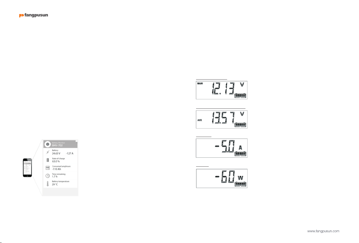
3.9.1 PC Software BMV-Reader
BMV-Reader will show all current readings on a computer, including history
data. It can also log the data to a CSV formatted file. It is available for free, and
can be downloaded from our website at the Support & Downloads section.
Connect the BMV to the computer with the VE.Direct to USB interface,
ASS030530000.
3.9.2 Large display and remote monitoring
The Color Control GX, a display featuring a 4.3” colour display, provides
intuitive control and monitoring for all products connected to it. The list of
Fangpusun products that can be connected are endless: Inverters, Multis,
Quattros, MPPT solar chargers, BMV-600, BMV-700, Skylla-i, Lynx Ion and
more. The BMV can be connected to the Color Control GX with a VE.Direct
cable. It is also possible to connect it with the VE.Direct to USB interface.
Besides monitoring and controlling locally with the Color Control GX, the
information is also forwarded to our free remote monitoring website: the VRM
Online Portal. For more information, see the Color Control GX documentation
on our website.
3.9.3 Custom integration (programming required)
The VE.Direct communications port can be used to read data and change
settings. The VE.Direct protocol is extremely simple to implement.
Transmitting data to the BMV is not necessary for simple applications: the
BMV automatically sends all readings every second. All the details are
explained in this document:
http://www.fangpusun.com
3.10 Additional functionality of the BMV-702
In addition to the comprehensive monitoring of the main battery system, the
BMV-702 provides a second monitoring input. This secondary input has three
configurable options, described below.
3.10.1 Auxiliary battery monitoring
Wiring diagram: see the quick installation guide. Fig 3
This configuration provides basic monitoring of a second battery, displaying
its voltage. This is useful for systems with a separate starter battery.
3.10.2 Battery temperature monitoring
Wiring diagram: see the quick installation guide. Fig 4
The cable with integrated temperature sensor has to be purchased separately
(part no: ASS000100000). This temperature sensor is not interchangeable
with other Fangpusun temperature sensors, as provided with Multis or battery
chargers. The temperature sensor must be connected to the positive pole of
the battery bank (one of the two wires of the sensor doubles as the power
supply wire).
The temperature can be displayed in degrees Celsius or degrees Fahrenheit,
see section 4.2.5, setting number 67.
The temperature measurement can also be used to adjust battery capacity to
temperature, see section 4.2.5, setting number 68.
The available battery capacity decreases with temperature. Typically, the
reduction, compared to the capacity at 20°C, is 18% at 0°C and 40% at -
20°C.
3.10.3 Midpoint voltage monitoring
Wiring diagram: see the quick installation guide. Fig 5 - 12
One bad cell or one bad battery can destroy a large, expensive battery bank.
A short circuit or high internal leakage current in one cell for example will result
in under charge of that cell and over charge of the other cells.
Similarly, one bad battery in a 24V or 48V bank of several series/parallel
connected 12V batteries can destroy the whole bank.
Moreover, when cells or batteries are connected in series, they should all have
the same initial state-of-charge. Small differences will be ironed out during
absorption or equalise charging, but large differences will result in damage
during charging due to excessive gassing of the cells or batteries with the
highest initial state-of-charge.
A timely alarm can be generated by monitoring the midpoint of the battery
bank. For more information, see section 5.1.