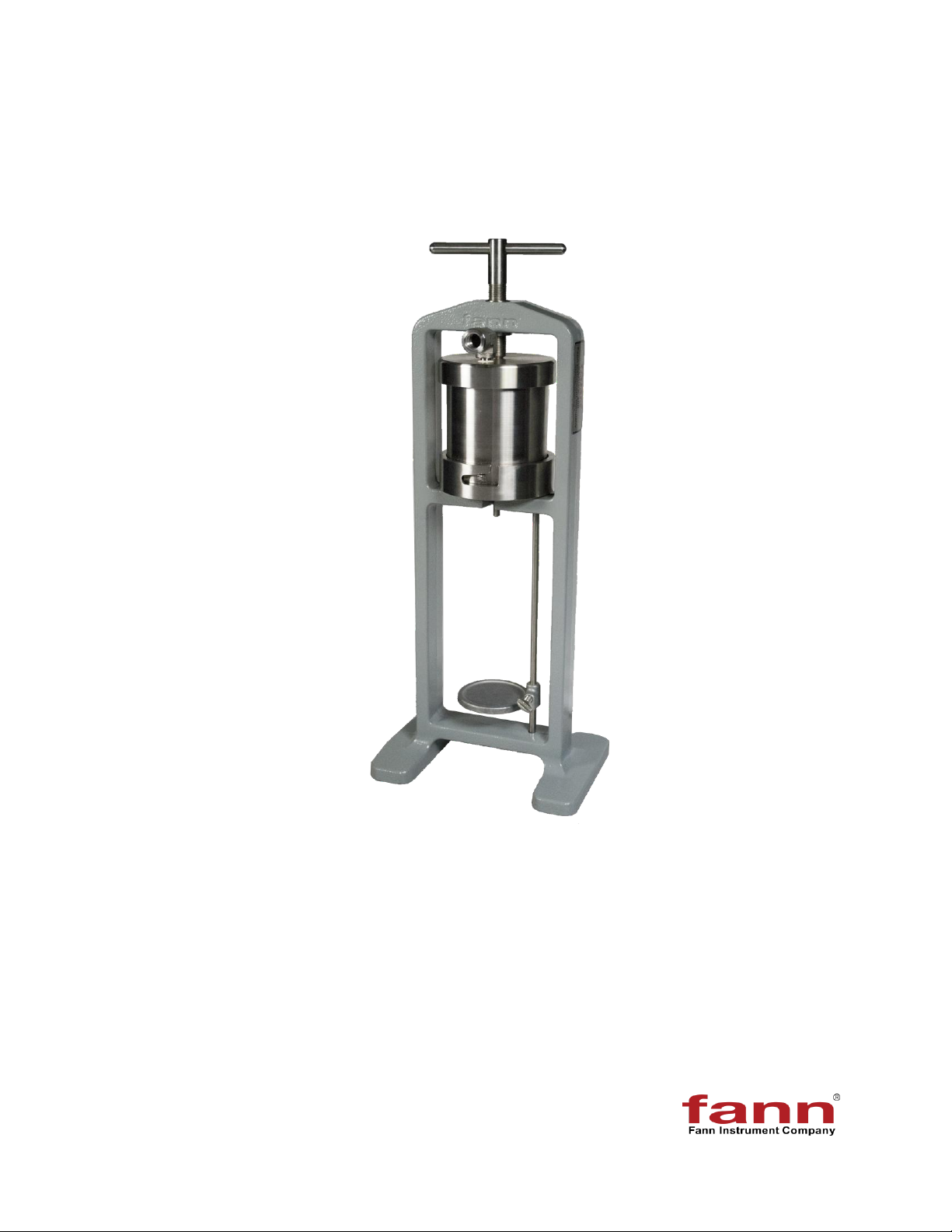
LPLT Filter Press Instruction Manual
207128 Revision G, September 2012 3
Table of Contents
1 Introduction ..............................................................................................................6
1.1 Document Conventions....................................................................................7
2 Safety.......................................................................................................................8
2.1 Safe Pressurization..........................................................................................8
3 Features and Specifications ...................................................................................10
4 Pressure Sources...................................................................................................11
4.1 Carbon Dioxide Pressure Source................................................................... 11
4.2 Nitrogen Cylinder Pressure Source................................................................13
4.3 Dead-Weight Hydraulic Pressure Source.......................................................14
4.4 External Pressure Source ..............................................................................15
5 Installation..............................................................................................................16
6 Standard Filter Press Test Procedures...................................................................17
7 Test Analysis.........................................................................................................20
7.1 References.....................................................................................................20
7.2 Results........................................................................................................... 20
8 Troubleshooting and Maintenance .........................................................................21
8.1 Cleaning.........................................................................................................21
8.2 Pressure Regulator Maintenance and Repair................................................. 21
8.3 Dead Weight Hydraulic Unit Maintenance...................................................... 25
9 Accessories............................................................................................................26
10 Parts List................................................................................................................27
11 Warranty and Returns............................................................................................ 38
11.1 Warranty ........................................................................................................38
11.2 Returns ..........................................................................................................38