Fantasia Elite Cirrus Setup guide

OWNERS INSTRUCTION
MANUAL
INSTALLATION
OPERATION
MAINTENANCE
102CM/40”
Cirrus
CAUTION
READ INSTRUCTIONS CAREFULLY FOR SAFE
INSTALLATION AND FAN OPERATION. IF UNSURE CONSULT
A QUALIFIED ELECTRICIAN
SUITABLE FOR 230V/50 CYCLE ELECTRICAL SUPPLY
Enquiries on installing your fan please call our help line on
01959-564440
E-mail :


IMPORTANT NOTES :
Please minimise risk of electrical shock by switching off electricity supply at the
main circuit breaker. And read the following point carefully.
To ensure the success of the installation be sure to read the instructions and study the diagrams
thoroughly before commencing.
All electrical work should only be undertaken after disconnection of the power by removing fuses
or turning off the circuit breaker to ensure all pole isolation of the electrical supply. If you are in any
doubt the services of a qualified electrician should be sought to ensure that all work is carried out
in accordance with the I.E.E. Regulations, current good practice and other national and local
electrical codes.
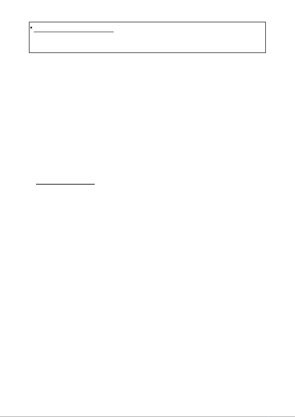
Make sure that your installation site will not allow the rotating fan blades to come into contact with
any object and that there is a minimum clearance of 150mm (6”) from the blade tip to the wall or
ceiling. Please note that the bigger this clearance is the better the airflow from your fan will be.
Ensure the blades are mounted at a minimum height of 2.3 meters (7’6”) from the floor when the
fan is installed.
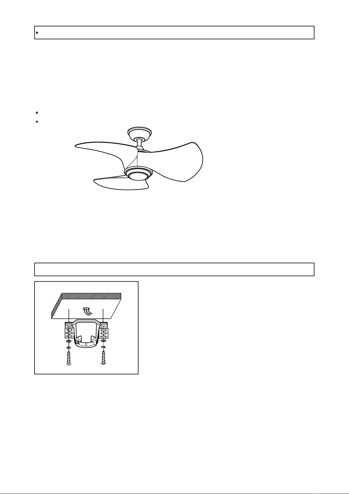
The fixing point for the fan must be able to support a weight ten times that of the net weight of the
fan. Net weights can be found on the bottom of the unit’s box. If you are mounting the fan to a
ceiling junction box, the box and it’s fixing must be able to support the moving weight of the fan
and must not twist or work loose.
The fan must be earthed.
Do not connect the fan motor to a dimmer switch. This may give an unsatisfactory performance
(motor hum) and cause damage to the motor.
It is not recommended that ceiling fans and gas appliances are operated in the same room at the
same time.
The fan must be turned off and stopped completely before reversing the fan direction. This will
prevent any damage to the motor of the unit or controller (if installed).
Do not insert anything into the fan blades while the fan is operating. This will damage the blades
and upset the balance of the unit causing the unit to wobble.
After the fan is completely installed make sure that all connections are secure and tight to prevent
any problems.
Because of the fan’s natural movement, some connections may loosen. Check the support
connections, brackets and blade attachments twice a year to make sure they are all secure. If they
are loose tighten with a screwdriver. ( It is not necessary to take the fan down from the ceiling )
1.
2.
3.
4.
5.
6.
7.
8.
9.
10.
11.
Note : The important safeguards and instructions given in this manual are not meant to cover all
possible conditions and situations that may occur. It must be understood that common sense,
caution and care are factors, which cannot be built into any product. These factors must be supplied
by the persons caring for and using the unit.
For installation advice, or in the unlikely event of damaged or missing parts please ring:
HELP LINE : (01959) 564440

Canopy Decorative Plate
PART LIST
Mounting Screw
Hanger Bracket
Drop Rod
Canopy
Split Pin
Boss Cover
Canopy Screw
Cotter Pin
Fan Motor
Light Plate
Light Plate Screw
Push Connector
Glass shade
LED Light Fitter
blade support plate
Round Steel Washer
Spring Steel Washer
Joist of Beam
Blade
Light Fitter Screw
Handset
Receiver
Blade Set Screw
Blade Set Screw

Installing the fan
1. Hanger bracket installation
Picture A
Drop Rod Style
All electrical work should only be undertaken after disconnection of the power by removing fuses or
turning off the circuit breaker to ensure all pole isolation of the electrical supply.
Your fan can be installed in a drop rod style of fan (Picture A). In this situation the drop rod assembly
is used to lower the fan down from it’s mounting position slightly. Extension rods, ranging from 12”
to 72” (your fan is supplied with 6” Drop rod in the box), are available if you need to lower your fan
further. (This is normally the case in conservatories or rooms with very high ceilings.)
The following steps will guide you to a successful installation:
Hanging bracket installation
Down rod assembly style
The hanger bracket should be screwed on to a firm flat
surface. The fixing location must be able to withstand ten
times the static weight of the fan. If you have any doubts as
to the ability of your intended fixing location to be able to
withstand this loading. Please contact our service help-line
or another competent authority to advise you. In most
situation two wood screws screwed into a wooden joist is
more than adequate to support your ceiling fan. The hanger
bracket should be screwed onto the joist with the two wood
screws provided. The washers provided should go in the
following sequence:
Screw head > spring washer > round washer>Hanger bracket > Ceiling. Screw the hanger bracket to
the ceiling and make sure all connections are secure to prevent the fan from falling. Fixings must
screw into a joist and not just the plasterboard. Loosen the two canopy screws from the hanger
bracket.
1.
2.
Attaching the blades4.
Attaching the light plate and LED light fitter and glass5.
Remote Control function and setup6.
Remote Control and Wiring instructions3.

2. Drop rod assembly
Remove the cotter pin and cross pin from the drop rod
boss of the fan. If a longer drop rod (12” to 72” rod) is
going to be used transfer the ball joint and the earth
wire to the longer rod.
Put the drop rod through the flared end of the canopy
and pass the electrical supply leads from the top of the
motor through the drop rod and boss cover and
canopy decorative plate until they exit at the top of the
rod. Always ensure the rod passes through the
canopy and boss cover before the rod is connected to
the fan If an extension rod longer than 18” inches is to
be used, the cables will need to be extended in an
appropriate way.
FOR DROP ROD STYLE OF FAN:
Rotate the ball around until the groove in the side of
the ball aligns with the protrusion on the upper edge of
the recess. When aligned the fan should drop slightly
as it assumes it’s correct position.
This is to prevent rotation of the rod and fan when the
unit is working.
REFER TO THE WIRING INSTRUCTIONS NEXT.
Carefully lift the fan motor assembly up to the hanger
bracket and seat the hanger ball/downrod assembly in
the mounting bracket socket.
Loosen the drop rod set screws on the boss, which is
on top of the motor and insert the drop rod into the
drop rod boss on top of the motor casing. Turn gently
to align the holes in the boss with those in the rod.
Ease the split pin through the boss and the rod taking
care not to pinch or damage any cables. Fix in place by
replacing the cotter pin.
Tighten all set screws at this point. This prevents the
rod and the fan moving in relation to one and other. It
also assists in maintaining a good earth continuity
through the fan, which is important to the safety of the
unit.
Failure to tighten the locking screws down may cause
the motor to oscillate badly.

3. Remote Control and Wiring Instructions
Warning: The power should have already been
disconnected. Follow the steps below to connect the
fan to your household wiring.
Insert the receiver into the hanger bracket with the
flat side of the receiver facing the ceiling.
Put the receiver of remote control through hanger bracket (as picture).
Connect the A.C. power supply wire that come from the ceiling to the Brown and blue wire of receiver
which is mark with label “L” & “N”. In most cases, BROWN/RED wire is LIVE is connected to “L”
BROWN wire , BLUE/BLACK wire is NEUTRAL is connected to “N” BLUE wire. GREEN/YELLOW wire
is EARTH.
Connect the 4 lead wires coming from the fan housing with 4 wires coming from the other side of the
remote control receiver where indicated sticker with brown, blue, orange block.
BROWN TO BROWN (Live wire of fan)
BLUE TO BLUE (Neutral wire of fan)
ORANGE TO ORANGE (Live wire of light)
GRN/YEL TO GRN/YEL (Earth wire)
BROWN (RECEIVER AC IN L) BROWN (” L” FROM RECEIVER)
BROWN (” L” FROM HOUSEHOLD)
BROWN (” L” FROM FAN)
ORANGE (” L1” FROM FAN)
ORANGE (” L1” FROM RECEIVER)
BLUE (” N” FROM FAN)
BLUE (” N” FROM RECEIVER)
BLUE ( RECEIVER AC IN N)
GRN/YEL (FROM BRACKET)
GRN/YEL (FROM FAN)
GRN/YEL (FROM HOUSEHOLD)
BLUE (FROM HOUSEHOLD)
RECEIVER

Put all the wires carefully into canopy after finishing
all the wires connection. Make sure connection
are neatly tucked in the canopy.
Slide the canopy up to the mounting bracket and place
the key hole on the canopy over the loose canopy
mounting screw on the mounting bracket. Turn the
canopy clockwise until the canopy locks in place at the
narrow section of the key holes.
Align the circular hole on the canopy with the remaining
hole on the mounting bracket. Secure the canopy
mounting screw previously removed in the hole, and
tighten the two canopy mounting screw.
Attach the canopy bottom cover to the canopy by
inserting the canopy mounting screw into the key
slots in the canopy bottom cover and rotating the
canopy bottom cover clockwise.

4. Attaching the blades
Remove the decorative cover from the fan motor housing
by remove the two decorative cover screws on the motor
housing.
Remove three blade upper section attachment screws
from the fan motor through the motor window.
Secure fan upper section with the screw previously
removed through the motor window.
Align three holes on blade support plate with three
holes on blade lower section and on blade arm, and
secure with three blade lower section attachment
screws with lock washers provided.
Repeat this procedure for remaining blades.
Re-install the decorative cover back to the fan motor
housing by using the two decorative cover screws
previously removed.

5. Attaching the light plate and LED light fitter and glass
The fan motor assembly is shipped with motor support
plate to prevent movement during transportation.
Remove the motor support plate .
Remove one of the three light kit mounting plate screws
from the mounting ring and loosen the other two screws.
(Do not remove.)
Place the key holes in the light kit mounting plate over
the two screws previously loosened from the mounting
ring. Turn the light kit mounting plate until the light kit
mounting plate locks in place at the narrow section of
the key holes.
Securely tighten the two light kit mounting plate screws
previously loosened and the one previously removed.
Remove one of the three light kit mounting screws from
the light kit mounting plate and loosen the other two
screws. (Do not remove.)
While holding the 18W LED light kit under the fan motor
assembly, make the 2-pin wire connections:
- White to white
- Black to black
Place the key holes in the 18W LED light kit over the two
mounting screws previously loosened from the light kit
mounting plate. Turn the 18W LED light kit until the 18W
LED light kit locks in place at the narrow section of the
key holes. Secure by tightening the two light kit mount-
ing screws previously loosened and the one previously
removed.
Position the notches in the outer rim of the 18W LED
light kit so they line up with the tabs on the inside of the
rim on the light cover. Carefully lift the light cover up
inside the 18W LED light kit and secure it to the fan by
turning the light cover clockwise until snug. DO NOT
OVERTIGHTEN.

6. Remote Control function and setup
RECEIVER TRANSMITTER
PLEASE NOTE :
Before installation ensure that the electricity supply is disconnected and that all wiring is carried out
in accordance with I.E.E. Regulations, current good practice, national and local electrical codes.
Improper installation may result in an electrical short and may void your warranty.
IMPORTANT : THIS APPLIANCE MUST BE EARTHED.
Set screw
OPERATING INSTRUCTIONS
A. H, M and L buttons:
These three buttons are used to set the fan
speed as follows:
H= high speed
M= medium speed
L= low speed
B. button:
This button turns the fan off.
C. The " " button:
The " " button turns the light ON or OFF
and also controls the brightness setting.
Press and hold the button to dim and
brighten the light. Press and hold the
button and release the button at desired
brightness. The light key has an auto-re-
sume, it will stay at the same brightness as
the last time it was turned off.
D. " , and " buttons:
Pressing the timer buttons will automatically
turn fan off after 2, 4, or 8 hours.
Please note that the timer buttons are active only
when the fan speeds turn on. the light is not
included.
You can cancel the timer by pressing button
and re-start the fan speed.
NOTE: The distance between the transmitter and
receiver should not be greater than 30 feet. For
best performance, make sure the Black Antenna
on the end of the receiver unit remains extended
and not tangled with any of the electrical wires.
Remote pairing process:
NOTE: This unit is equipped with an automatically learning type remote control. There are no frequency
switches on the receiver and transmitter. The receiver unit will automatically scan the frequency from
the hand-held remote. This unit has 65,000 different code combinations.
Remove the set screw on the back of transmitter, take out the battery cover. Insert the 3 volt battery
(included) and make sure they are seated correctly in each recess with the Positive + sign facing up.
When removing or inserting the batteries, use a suitable screwdriver to loosen or tighten the screws and
open the back cover.
NOTE: To prevent damage to the transmitter, remove these batteries if not used for long periods of
time (months).
With the fan’s power off, restore power to the fan. Press and hold “ ” button for about 5 seconds and
release. The light kit will flash twice and the signal light on the handheld remote will come on when the
button is pressed. The fan has completed the pairing process with the handheld remote and is ready for
use.

This product has been classed as Electrical or Electronic
Equipment and should not be disposed of with other
household or commercial waste at the end of it’s working life.
The Waste of Electrical and Electronic Equipment (WEEE)
Directive (2002/96/EC) has been put in place to recycle
products using best available precise and minimize the impact
upon the environment.
Having checked that all electrical connections are securely made and insulated, turn on the power
and check the operation of the fan.
The slide switch on the other side of the housing changes the direction of rotation of the blades.
(Remember to let the fan slow to a complete stop before changing the direction of rotation). When
looking up at the fan blades, anti –clockwise rotation achieves a downward flow of air and clockwise
rotation achieves an upward movement of air.
Summer operation – In warm weather a downward movement of air is more desirable as this achieves
a greater cooling effect.
Winter operation – In winter a movement of air moving upwards and then back down the sides of the
room achieves a more balanced temperature throughout the room.
If a wall control or remote control system has been used refer to the accompanying leaflets enclosed
in these systems.
Product Disposal Instructions
Operating instructions
Whilst every precaution is taken at the factory to ensure your fan is of the highest quality, imbalance
may occur. This may be due to slight irregularities in the blades or blade carriers. Deviating from
these instructions can cause further problems.
The following procedure may help to rectify the situation.
The hanging bracket must always be tight against the ceiling so that no movement can occur.
Make sure that the rod is firmly locked into the boss on top of the fan. The locking screw should be
securely tightened.
Check all the blades are firmly tightened on to their fixings.
Blade tracking can easily be checked by holding a yardstick or similar measure vertically from the
ceiling to the tip of the blade. Then check all blades measure the same distance from that point. To
correct slight problems re-check the screws that hold the blades onto the motor for tightness.
Changing over two adjacent blades – may correct any imbalance.
Use the universal balancing kit supplied with the fan.
Please note that drop rod styles of fans do have a slight level of movement but this is in no way
dangerous.
Blade balancing
Ensure that checks of the fixings take place periodically. (see Safety Precaution 11)
Periodic cleaning of your new fan is recommended particularly the blades. The plated or painted
surfaces of your fan have been sealed with a lacquer to minimize any discoloration or tarnishing.
Therefore use a soft brush or lint free cloth to avoid scratching the surface.
The motor has permanently sealed bearings so no lubrication is necessary
Do not use water when cleaning you fan as this could damage the surfaces of the casing and the
blades and may create the possibility of a electric shock.
Care and cleaning

The following is NOT covered by warranty.
1. Any damage incurred after delivery to the owner that is not caused by a fault in the
products materials or workmanship; damage from lightning or power surges; incorrect
installation; damage due to incorrect installation; water damage of any kind;
installation or use outdoors; damage arising from connection to or use with alternative
power systems (e.g. inverters, solar, etc.).
2. Fantasia Ceiling fans not installed by a qualified electrician.
3. Repair of a ceiling fan used incorrectly, accidentally damaged, modified in any way or
not serviced in accordance with the maintenance instructions.
4. The cost of transporting and insuring the ceiling fan between the nearest Fantasia
Distribution Ltd agents' service depot and its normal location. These costs must be met
by the purchaser.
5. Subject to any statutory provisions to the contrary, claims for damage to furniture,
carpet, walls, ceilings, foundations or any other consequential loss either directly or
indirectly resulting from a faulty ceiling fan.
6. Fantasia Ceiling Fans not purchased and installed in Mainland UK.
7. A service fee will be charged where; there is nothing wrong with the ceiling fan or; the
defective operation of the ceiling fan is due to failure of electricity or; the installation is
not in accordance with Fantasia Distribution Ltd instructions and/or applicable local
regulations or; the defects have been caused by incorrect application or abuse of the
ceiling fan or; the damage has been caused by unauthorized persons attempting to
repair the fan.
Ceiling Fan Warranty.
You must have the original purchase receipt or bill of sale to make a warranty claim. No claim
will be accepted unless proof of date of purchase is available at the time of making the
warranty claim.
Ceiling Fan Warranty Period.
The ceiling fan itself, excluding accessories such as the Remote Control Transmitter and
Receiver, is covered by a 10 year warranty. During this period, Fantasia Distribution Ltd will,
at its discretion, repair or replace defective product. During this 10 years, the owner is
responsible for labour costs incurred in removing and re-installing the fan, and for transport
costs to Fantasia Distribution Ltd’s repair centre. Return freight will be paid by Fantasia
Distribution Ltd. The cost of obtaining or using special access equipment (scissor lifts,
scaffolding etc.) is specifically excluded, and it is the responsibility of the owner to provide
such equipment and have it safely installed and operated.
Remote Control Warranty Period.
Fantasia Distribution Ltd’s Remote Control Receivers and Transmitters (Handsets) are
covered by a 2 year repair or replacement warranty
Balance of Warranty on Repaired or Replaced Products.
Any replaced or repaired product is covered only by the balance of the warranty remaining
on the original article.
Transfer of Warranty.
If the dwelling where the fan or remote control is installed changes hands, the balance of the
warranty passes to the new owner, providing the original bill of sale for the product is
retained by the new owner.
Warranty for the fan does not cover damage to the fan if it is moved from one dwelling to
another during the warranty period. The warranty is voided in total if the product is sold as
second hand goods.

40”/102cm
Cirrus
FANTASIA DISTRIBUTION LTD.
Unit B. The Flyers Way, Westerham, Kent, TN16 1DE
Tel : (01959) 564 440 Fax : (01959) 564 829
E-MAIL: [email protected]


40”/102cm
Cirrus
Alternatively please go to our website www.fantasiaceilingfans.com and fill in the
warranty section there.
Please cut out this warranty page and send it in an envelope to the address
below.
FANTASIA DISTRIBUTION LTD.
Unit B. The Flyers Way, Westerham, Kent, TN16 1DE
Tel : (01959) 564 440 Fax : (01959) 564 829
E-MAIL: [email protected]
Table of contents
Other Fantasia Fan manuals

Fantasia
Fantasia Propeller Setup guide

Fantasia
Fantasia Elite Zeta Setup guide

Fantasia
Fantasia Mayfair Combi Setup guide

Fantasia
Fantasia Omega Setup guide

Fantasia
Fantasia Delta Setup guide

Fantasia
Fantasia Viper Setup guide

Fantasia
Fantasia Tau Setup guide

Fantasia
Fantasia Medina Setup guide

Fantasia
Fantasia GEMINI User manual

Fantasia
Fantasia Alpha Setup guide